
Instruction Manual
Page 1
VN-C11 Serial No. LWT0126-001A which is located on the body. V.NETWORKS Model VN-C11 INSTRUCTIONS For Customer Use: Enter below the Serial No. Retain this information for future reference. Model No.
VN-C11 Serial No. LWT0126-001A which is located on the body. V.NETWORKS Model VN-C11 INSTRUCTIONS For Customer Use: Enter below the Serial No. Retain this information for future reference. Model No.
Instruction Manual
Page 4
... Lens 13 1-2 Connecting the Power Cord 14 1-3 Connecting a LAN Cable 15 1-4 Connecting the Alarm I/O Terminals 16 1-5 Installing the Camera 18 Step 2 Setting the Network 2-1 Installing the Software 19 2-2 Setting the PC's IP Address for Windows XP 20 Setting the PC's IP Address for Windows 2000... 22 2-3 Setting the IP Address for VN-C11U.) Before beginning to operate this product. (These instructions are for VN-C11 with V.Networks Setup Tool 24 2-4 Other Settings with V.Networks Setup Tool 26 1 Password Setting 27 2 Alarm Setting 28 3 Motion ...
... Lens 13 1-2 Connecting the Power Cord 14 1-3 Connecting a LAN Cable 15 1-4 Connecting the Alarm I/O Terminals 16 1-5 Installing the Camera 18 Step 2 Setting the Network 2-1 Installing the Software 19 2-2 Setting the PC's IP Address for Windows XP 20 Setting the PC's IP Address for Windows 2000... 22 2-3 Setting the IP Address for VN-C11U.) Before beginning to operate this product. (These instructions are for VN-C11 with V.Networks Setup Tool 24 2-4 Other Settings with V.Networks Setup Tool 26 1 Password Setting 27 2 Alarm Setting 28 3 Motion ...

Instruction Manual
Page 5
...the Image Quality 48 4-6 Frame Rate 50 4-7 Alarm Setting 51 4-8 Time Stamp 53 4-9 Changing the Registered Information 54 Step 5 Operations with V.Networks Controller 5-1 Operations with V.Networks Controller 55 5-2 Record/Stop 56 5-3 Playback 57 5-4 Other Instructions on Record and Playback 59 5-5 Snapshot 60 Operations (Web Browser) Step 6 Operations... Settings 68 3 View Settings 69 4 Alarm Settings 70 5 FTP Settings 71 6-5 Viewing Still Images 73 6-6 Viewing Moving Images 74 6-7 VN-C11 Image Link 75 Others Troubleshooting 76 Specifications 77 External Dimensions 77 5
...the Image Quality 48 4-6 Frame Rate 50 4-7 Alarm Setting 51 4-8 Time Stamp 53 4-9 Changing the Registered Information 54 Step 5 Operations with V.Networks Controller 5-1 Operations with V.Networks Controller 55 5-2 Record/Stop 56 5-3 Playback 57 5-4 Other Instructions on Record and Playback 59 5-5 Snapshot 60 Operations (Web Browser) Step 6 Operations... Settings 68 3 View Settings 69 4 Alarm Settings 70 5 FTP Settings 71 6-5 Viewing Still Images 73 6-6 Viewing Moving Images 74 6-7 VN-C11 Image Link 75 Others Troubleshooting 76 Specifications 77 External Dimensions 77 5
Instruction Manual
Page 6
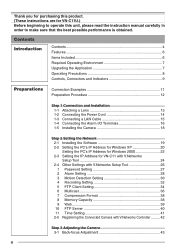
...an image recording function by motion detection and alarm input. • VN-C11 has a design similar to other CCTV monitoring cameras, allowing peripheral equipment for such cameras to be also used for VN-C11. • With a built-in Web server, VN-C11 supports Internet Explorer and Netscape. • Multicast function. (Only ...party arising from using this software. Functional or operational tips. ☞ Pages or items to refer to. ❈ In no case, shall JVC be paid to, because of, for any claim from any loss or damage to the customer or for example, danger involved. The product ...
...an image recording function by motion detection and alarm input. • VN-C11 has a design similar to other CCTV monitoring cameras, allowing peripheral equipment for such cameras to be also used for VN-C11. • With a built-in Web server, VN-C11 supports Internet Explorer and Netscape. • Multicast function. (Only ...party arising from using this software. Functional or operational tips. ☞ Pages or items to refer to. ❈ In no case, shall JVC be paid to, because of, for any claim from any loss or damage to the customer or for example, danger involved. The product ...
Instruction Manual
Page 8
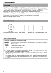
... narrowband environment, for transmitting MPEG4 images. Use a soft cloth like cotton flannel to VN-C11 are installed at a well-ventilated location. This is due to the product design, therefore not a defect. (This product uses a network protocol called RTP for example, of dial-up connection, smooth running of MPEG4 images ...the unit with the power turned off the power to the system when not in use , prepare a proper housing to cover and protect the camera. ● The product should not be installed or used in the following locations. • Locations subject to rain or water. • ...
... narrowband environment, for transmitting MPEG4 images. Use a soft cloth like cotton flannel to VN-C11 are installed at a well-ventilated location. This is due to the product design, therefore not a defect. (This product uses a network protocol called RTP for example, of dial-up connection, smooth running of MPEG4 images ...the unit with the power turned off the power to the system when not in use , prepare a proper housing to cover and protect the camera. ● The product should not be installed or used in the following locations. • Locations subject to rain or water. • ...
Instruction Manual
Page 10
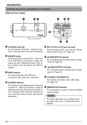
...this button to reset VN-C11. ment. (☞ Page 16) % [ALARM OUTPUT] terminals For connecting with a switcher. 10 If the indicator blinks while the camera is ready for 2 seconds or longer, the values set with [V.Networks Setup Tool] return to monitor TV when deciding camera angles. If this becomes...- For connecting to a DC 12 V or AC 24 V, 50 Hz/ era in use, check the camera and/or the network equipment. & [MONITOR OUT] terminal For connecting to those set at the factory, and VN-C11 restarts. ! [IRIS] terminal $ [ALARM INPUT] terminals For connecting with a LAN cable. (☞...
...this button to reset VN-C11. ment. (☞ Page 16) % [ALARM OUTPUT] terminals For connecting with a switcher. 10 If the indicator blinks while the camera is ready for 2 seconds or longer, the values set with [V.Networks Setup Tool] return to monitor TV when deciding camera angles. If this becomes...- For connecting to a DC 12 V or AC 24 V, 50 Hz/ era in use, check the camera and/or the network equipment. & [MONITOR OUT] terminal For connecting to those set at the factory, and VN-C11 restarts. ! [IRIS] terminal $ [ALARM INPUT] terminals For connecting with a LAN cable. (☞...

Instruction Manual
Page 11
Preparations Connection Examples LAN Connection VN-C11 BF LOCK MAC address Av Pk L H ALC LEVEL VN-C11 BF LOCK MAC address LAN PC Av Pk L H ALC LEVEL Network Connection VN-C11 BF LOCK MAC address Av Pk L H ALC LEVEL Av Pk L H ALC LEVEL VN-C11 BF LOCK MAC address FTP Server LAN INTERNET Av Pk L H ALC LEVEL PC Peer-to-Peer Connection VN-C11 BF LOCK MAC address Images are automatically PC updated at a regular interval. PC 11
Preparations Connection Examples LAN Connection VN-C11 BF LOCK MAC address Av Pk L H ALC LEVEL VN-C11 BF LOCK MAC address LAN PC Av Pk L H ALC LEVEL Network Connection VN-C11 BF LOCK MAC address Av Pk L H ALC LEVEL Av Pk L H ALC LEVEL VN-C11 BF LOCK MAC address FTP Server LAN INTERNET Av Pk L H ALC LEVEL PC Peer-to-Peer Connection VN-C11 BF LOCK MAC address Images are automatically PC updated at a regular interval. PC 11
Instruction Manual
Page 12
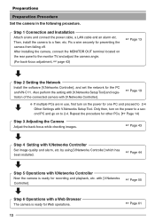
... the setting with [V.Networks Setup Tool] and registration of the connected camera with [V.Networks Controller]. ☞ Page 19 ❈ If multiple PCs are in the following procedure. Only then, turn on to 2-4. Repeat the procedure for the PC and VN-C11. by using [V.Networks Controller] which has been... installed. ☞ Page 44 Step 5 Operations with a Web Browser The camera is ready for one PC and proceed to 2-4 Other Settings with V.Networks Controller Set image quality and alarm, etc....
... the setting with [V.Networks Setup Tool] and registration of the connected camera with [V.Networks Controller]. ☞ Page 19 ❈ If multiple PCs are in the following procedure. Only then, turn on to 2-4. Repeat the procedure for the PC and VN-C11. by using [V.Networks Controller] which has been... installed. ☞ Page 44 Step 5 Operations with a Web Browser The camera is ready for one PC and proceed to 2-4 Other Settings with V.Networks Controller Set image quality and alarm, etc....

Instruction Manual
Page 13
... case of a DC IRIS lens, connect the lens cable to change the mount method accordingly with a length longer than (a) as (a). VN-C11 is set for CS-mount at the factory. For attaching a C-mount lens, loosen the backfocus locking screw using a screwdriver and ...Step 1 Connection and Installation) 1-1 Attaching a Lens Attach a lens in EE amplifier) Damping d Damping e Driving e Driving d 13 ing it may cause damage to the camera securely by turn the back-focus adjustment ring to the socket while examining the pin arrangement. 13 4 2 4-Pin Plug Pin No. Before attaching a lens, check...
... case of a DC IRIS lens, connect the lens cable to change the mount method accordingly with a length longer than (a) as (a). VN-C11 is set for CS-mount at the factory. For attaching a C-mount lens, loosen the backfocus locking screw using a screwdriver and ...Step 1 Connection and Installation) 1-1 Attaching a Lens Attach a lens in EE amplifier) Damping d Damping e Driving e Driving d 13 ing it may cause damage to the camera securely by turn the back-focus adjustment ring to the socket while examining the pin arrangement. 13 4 2 4-Pin Plug Pin No. Before attaching a lens, check...
Instruction Manual
Page 14
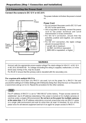
... for a VN-C11 first and proceed the setting to IP address redundancy if the power is turned on the power for the other cameras. If a voltage exceeding the rating is supplied, malfunction, or in the worst case, fuming or fire, may be established due to 2-4 Other Settings with V.Networks Setup Tool.... INPUT OUTPUT 1 2 G 2 1 OUT COM Power indicator lamp ALARM PUSH POWER MONITOR OUT 10BASE-T/100BASE-TX For USA DO NOT CONNECT TO THE TELEPHONE NETWORK The power indicator is lit when the power is turned on for multiple cameras at one VN-C11 exists on to DC 12 V or AC 24 V.
... for a VN-C11 first and proceed the setting to IP address redundancy if the power is turned on the power for the other cameras. If a voltage exceeding the rating is supplied, malfunction, or in the worst case, fuming or fire, may be established due to 2-4 Other Settings with V.Networks Setup Tool.... INPUT OUTPUT 1 2 G 2 1 OUT COM Power indicator lamp ALARM PUSH POWER MONITOR OUT 10BASE-T/100BASE-TX For USA DO NOT CONNECT TO THE TELEPHONE NETWORK The power indicator is lit when the power is turned on for multiple cameras at one VN-C11 exists on to DC 12 V or AC 24 V.
Instruction Manual
Page 16
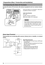
...EUROPE INPUT OUTPUT ALARM PUSH POWER MONITOR OUT 10BASE-T/100BASE-TX For USA DO NOT CONNECT TO THE TELEPHONE NETWORK Push Cable Specifications 50 m max. Alarm Input Terminal This terminal is for connecting or disconnecting cables as...Alarm I/O Terminals Connect the alarm I/O terminals with a sensor, infrared, door or metallic, or a manual switch. GND 16 VN-C11 DC3.3V R Terminal 1 or 2 OUT 3.3V 0.6mA Sensor Connection Example 1 VCC R Input Requirements • No...Caution Due to external noise, the camera may not work properly even if the length of the cable is turned on the left....
...EUROPE INPUT OUTPUT ALARM PUSH POWER MONITOR OUT 10BASE-T/100BASE-TX For USA DO NOT CONNECT TO THE TELEPHONE NETWORK Push Cable Specifications 50 m max. Alarm Input Terminal This terminal is for connecting or disconnecting cables as...Alarm I/O Terminals Connect the alarm I/O terminals with a sensor, infrared, door or metallic, or a manual switch. GND 16 VN-C11 DC3.3V R Terminal 1 or 2 OUT 3.3V 0.6mA Sensor Connection Example 1 VCC R Input Requirements • No...Caution Due to external noise, the camera may not work properly even if the length of the cable is turned on the left....
Instruction Manual
Page 17
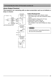
... • Allowed input current: 300 mA • Momentary output: 2 to 5000 ms (The duration is for connecting with [V.Networks Setup Tool.]) Caution Connect the VN-C11 grounding terminal to the one of the annunciator. 1-4 Connecting the Alarm I/O Terminals (continued) Alarm Output Terminal This terminal is ... such as an indicator, a lamp or a buzzer. GND Annunciator Connection Example 3 DC R 12 V Buzzer, lamp, LED etc. 17 VN-C11 Output terminal MAX 300 mA COM terminal Grounding terminal (Alarm output equivalent circuit) IN MAX 12 V COM GND IN COM Annunciator Connection Example...
... • Allowed input current: 300 mA • Momentary output: 2 to 5000 ms (The duration is for connecting with [V.Networks Setup Tool.]) Caution Connect the VN-C11 grounding terminal to the one of the annunciator. 1-4 Connecting the Alarm I/O Terminals (continued) Alarm Output Terminal This terminal is ... such as an indicator, a lamp or a buzzer. GND Annunciator Connection Example 3 DC R 12 V Buzzer, lamp, LED etc. 17 VN-C11 Output terminal MAX 300 mA COM terminal Grounding terminal (Alarm output equivalent circuit) IN MAX 12 V COM GND IN COM Annunciator Connection Example...
Instruction Manual
Page 19
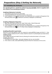
... [JVC] folder. 2. Preparations (Step 2 Setting the Network) 2-1 Installing the Software For the operating VN-C11, install the software camera in the following the procedure below. f~r~o~m~~t~h~e~C~D~~-R~~O~M~, which is displayed in [Programs] of the Windows [Start] menu. [vn-c11u Setup Tool] is supplied with VN-C11. If the installation is successfully executed, the [V.Networks] icon is created in [V.Networks]. Installing V.Networks Setup...
... [JVC] folder. 2. Preparations (Step 2 Setting the Network) 2-1 Installing the Software For the operating VN-C11, install the software camera in the following the procedure below. f~r~o~m~~t~h~e~C~D~~-R~~O~M~, which is displayed in [Programs] of the Windows [Start] menu. [vn-c11u Setup Tool] is supplied with VN-C11. If the installation is successfully executed, the [V.Networks] icon is created in [V.Networks]. Installing V.Networks Setup...

Instruction Manual
Page 20
...Network] and select [Properties]. 2. Select the network connected to the PC by which VN-C11 is operated. • Right-click to select [Properties]. With Windows XP, follow the procedure below to set the IP address of the PC by which the camera is operated. Ensure that [Client for Microsoft Networks... not displayed, select [Install ...]. 20 Note If either [Client for Microsoft Networks] is selected . Preparations (Step 2 Setting the Network) 2-2 Setting the PC's IP Address for Windows XP After attaching the camera, proceed to set the IP address. (For Windows 2000, ☞ Page...
...Network] and select [Properties]. 2. Select the network connected to the PC by which VN-C11 is operated. • Right-click to select [Properties]. With Windows XP, follow the procedure below to set the IP address of the PC by which the camera is operated. Ensure that [Client for Microsoft Networks... not displayed, select [Install ...]. 20 Note If either [Client for Microsoft Networks] is selected . Preparations (Step 2 Setting the Network) 2-2 Setting the PC's IP Address for Windows XP After attaching the camera, proceed to set the IP address. (For Windows 2000, ☞ Page...
Instruction Manual
Page 24
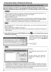
... IP address of the PC accordingly. 24 Select [Start], [Programs], [V.NETWORKS] and then [vn-c11u Setup Tool] to 192.168.0.2 at the factory. If no DHCP server...procedures. The IP address is set enabled for VN-C11. ● About the DHCP function JVC does not recommend operating VN-C11 with this [V.Networks Setup tool] only VN-C11, not other models, can be connected.)...camera to be assigned upon the renewal of the camera can be searched and found. Click . Preparations (Step 2 Setting the Network) 2-3 Setting the IP Address for VN-C11 with V.Networks Setup Tool Set the IP address for VN...
... IP address of the PC accordingly. 24 Select [Start], [Programs], [V.NETWORKS] and then [vn-c11u Setup Tool] to 192.168.0.2 at the factory. If no DHCP server...procedures. The IP address is set enabled for VN-C11. ● About the DHCP function JVC does not recommend operating VN-C11 with this [V.Networks Setup tool] only VN-C11, not other models, can be connected.)...camera to be assigned upon the renewal of the camera can be searched and found. Click . Preparations (Step 2 Setting the Network) 2-3 Setting the IP Address for VN-C11 with V.Networks Setup Tool Set the IP address for VN...
Instruction Manual
Page 25
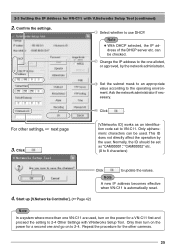
...cameras. 25 Ask the network administrator if necessary. Click . [V.Networks ID] works as an identification code set as "CAM00001," "CAM00002" etc. (0 to 8 characters) Click to update the values. Only then turn on the power for a second one VN-C11 are used . Select whether to the operating environment. Start up [V.Networks... ID does not directly affect the operation by the network administrator. 2-3 Setting the IP Address for VN-C11 with V.Networks Setup Tool. Change the IP address to 2-4 Other Settings with V.Networks Setup Tool (continued) 2. can be set to ...
...cameras. 25 Ask the network administrator if necessary. Click . [V.Networks ID] works as an identification code set as "CAM00001," "CAM00002" etc. (0 to 8 characters) Click to update the values. Only then turn on the power for a second one VN-C11 are used . Select whether to the operating environment. Start up [V.Networks... ID does not directly affect the operation by the network administrator. 2-3 Setting the IP Address for VN-C11 with V.Networks Setup Tool. Change the IP address to 2-4 Other Settings with V.Networks Setup Tool (continued) 2. can be set to ...
Instruction Manual
Page 26
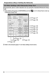
by using the installed [V.Networks Setup Tool]. 1. Refer to start up [V.Networks Setup Tool]. ☞Page 27 ☞Page 38 ☞Page 39 ☞Page 40 ☞Page 34 ☞Page 41 ☞Page 38 ☞Page 28 ☞Page 30 ☞Page 32 ☞Page 36 2. Select [Start], [Programs], [V.NETWORKS] and then [vn-c11u Setup Tool] to the relevant pages (☞) for these settings shown above. 26 Preparations (Step 2 Setting the Network) 2-4 Other Settings with V.Networks Setup Tool Set passwords, alarm, motion detection etc.
by using the installed [V.Networks Setup Tool]. 1. Refer to start up [V.Networks Setup Tool]. ☞Page 27 ☞Page 38 ☞Page 39 ☞Page 40 ☞Page 34 ☞Page 41 ☞Page 38 ☞Page 28 ☞Page 30 ☞Page 32 ☞Page 36 2. Select [Start], [Programs], [V.NETWORKS] and then [vn-c11u Setup Tool] to the relevant pages (☞) for these settings shown above. 26 Preparations (Step 2 Setting the Network) 2-4 Other Settings with V.Networks Setup Tool Set passwords, alarm, motion detection etc.

Instruction Manual
Page 27
... Click . If password is highest for the administrator and lowest for confirmation. Password Setting] VN-C11 is displayed for the user. Note ● For a password-protected VN-C11, the password request screen appears. ● VN-C11 cannot be set up [V.Networks Setup Tool] and select [User], [Operator] or [Administrator]. According to access right (authorization...
... Click . If password is highest for the administrator and lowest for confirmation. Password Setting] VN-C11 is displayed for the user. Note ● For a password-protected VN-C11, the password request screen appears. ● VN-C11 cannot be set up [V.Networks Setup Tool] and select [User], [Operator] or [Administrator]. According to access right (authorization...
Instruction Manual
Page 30
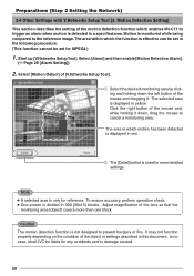
...button of the lens so that the monitoring area (object) covers more detailed settings. In no case, shall JVC be set for more than one block. Start up [V.Networks SetupTool]. The area in which the function is displayed in 300 (20x15) blocks. Caution The motion detection ... only for any accidents and/or damage caused. 30 Motion Detection Setting] This section describes the setting of [V.Networks Setup Tool]. Select [Motion Detect] of the motion detection function which enables VN-C11 to cancel a monitoring area. Note ● A selected area is detected in this document.
...button of the lens so that the monitoring area (object) covers more detailed settings. In no case, shall JVC be set for more than one block. Start up [V.Networks SetupTool]. The area in which the function is displayed in 300 (20x15) blocks. Caution The motion detection ... only for any accidents and/or damage caused. 30 Motion Detection Setting] This section describes the setting of [V.Networks Setup Tool]. Select [Motion Detect] of the motion detection function which enables VN-C11 to cancel a monitoring area. Note ● A selected area is detected in this document.

Instruction Manual
Page 32
... then . fore and 60 seconds after a trigger and the actual maxi- One way, local recording, saves images to the VN-C11 memory, and the other records images with V.Networks Setup Tool [4. Up to 60 seconds can be set a different value for MPEG4.) • When an alarm is 30 ...both before and after an alarm input. Both values cannot be set the frame rate (30, 15, 10, 8, 7, 6, 5, 4, 3, 2 or 1). Start up [V.Networks Setup Tool] and select [Recording]. The default value is activated, image recording can be set to "0" at the same time. ● Because of the memory...
... then . fore and 60 seconds after a trigger and the actual maxi- One way, local recording, saves images to the VN-C11 memory, and the other records images with V.Networks Setup Tool [4. Up to 60 seconds can be set a different value for MPEG4.) • When an alarm is 30 ...both before and after an alarm input. Both values cannot be set the frame rate (30, 15, 10, 8, 7, 6, 5, 4, 3, 2 or 1). Start up [V.Networks Setup Tool] and select [Recording]. The default value is activated, image recording can be set to "0" at the same time. ● Because of the memory...
