Instruction Manual
Page 4
...PC's IP Address for Windows 2000 22 2-3 Setting the IP Address for VN-C11U.) Before beginning to operate this product. (These instructions are for VN-C11 with V.Networks Setup Tool 24 2-4 Other Settings with V.Networks Setup Tool 26 1 Password Setting 27 2 Alarm Setting 28 3 Motion ... 38 8 Memory Capacity 38 9 Web 39 10 FTP Server 40 11 Time Setting 41 2-5 Registering the Connected Camera with V.Networks Controller .......... 42 Step 3 Adjusting the Camera 3-1 Back-focus Adjustment 43 4 Thank you for purchasing this unit, please read the instruction manual carefully in order...
...PC's IP Address for Windows 2000 22 2-3 Setting the IP Address for VN-C11U.) Before beginning to operate this product. (These instructions are for VN-C11 with V.Networks Setup Tool 24 2-4 Other Settings with V.Networks Setup Tool 26 1 Password Setting 27 2 Alarm Setting 28 3 Motion ... 38 8 Memory Capacity 38 9 Web 39 10 FTP Server 40 11 Time Setting 41 2-5 Registering the Connected Camera with V.Networks Controller .......... 42 Step 3 Adjusting the Camera 3-1 Back-focus Adjustment 43 4 Thank you for purchasing this unit, please read the instruction manual carefully in order...
Instruction Manual
Page 8
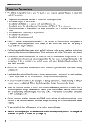
... • Locations subject to the product design, therefore not a defect. (This product uses a network protocol called RTP for indoor use , prepare a proper housing to cover and protect the camera. ● The product should not be viewed properly. ● To save electricity, turn off ...8226; Locations with SNMP functions have vertical lines (smear) or blur (blooming) at a well-ventilated location. Introduction Operating Precautions ● VN-C11 is designed for transmitting MPEG4 images. This is a characteristic of the CCD, and is enabled, multicast images created by this may ...
... • Locations subject to the product design, therefore not a defect. (This product uses a network protocol called RTP for indoor use , prepare a proper housing to cover and protect the camera. ● The product should not be viewed properly. ● To save electricity, turn off ...8226; Locations with SNMP functions have vertical lines (smear) or blur (blooming) at a well-ventilated location. Introduction Operating Precautions ● VN-C11 is designed for transmitting MPEG4 images. This is a characteristic of the CCD, and is enabled, multicast images created by this may ...
Instruction Manual
Page 10
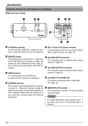
.... (A video iris lens cannot be connected.) @ [POWER] indicator ^ [10 BASE-T/100 BASE-TX] For network connection with an external alarm equip- If the indicator blinks while the camera is in a way that does not cover the opening # [DC 12 V/AC 24 V] Power terminal For ...(☞ Page 16) % [ALARM OUTPUT] terminals For connecting with a switcher. 10 When the camera is ready for 2 seconds or longer, the values set with [V.Networks Setup Tool] return to those set at the factory, and VN-C11 restarts. ! [IRIS] terminal $ [ALARM INPUT] terminals For connecting with a LAN cable...
.... (A video iris lens cannot be connected.) @ [POWER] indicator ^ [10 BASE-T/100 BASE-TX] For network connection with an external alarm equip- If the indicator blinks while the camera is in a way that does not cover the opening # [DC 12 V/AC 24 V] Power terminal For ...(☞ Page 16) % [ALARM OUTPUT] terminals For connecting with a switcher. 10 When the camera is ready for 2 seconds or longer, the values set with [V.Networks Setup Tool] return to those set at the factory, and VN-C11 restarts. ! [IRIS] terminal $ [ALARM INPUT] terminals For connecting with a LAN cable...
Instruction Manual
Page 12
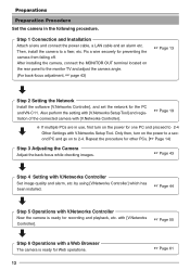
... an alarm etc. Fix a wire securely for the PC and VN-C11. Repeat the procedure for other PCs. (☞ Page 14) Step 3 Adjusting the Camera Adjust the back-focus while checking images. ☞ Page 43 Step 4 Setting with V.Networks Controller Now the camera is ready for recording and playback, etc. Preparations Preparation Procedure Set...
... an alarm etc. Fix a wire securely for the PC and VN-C11. Repeat the procedure for other PCs. (☞ Page 14) Step 3 Adjusting the Camera Adjust the back-focus while checking images. ☞ Page 43 Step 4 Setting with V.Networks Controller Now the camera is ready for recording and playback, etc. Preparations Preparation Procedure Set...
Instruction Manual
Page 14
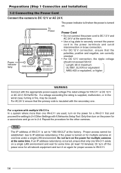
... AC 24 V, ensure that the polarities, positive and negative, are used, turn on the power for a second one and go on again for multiple cameras at one VN-C11 are correctly oriented. • For DC 12 V connection, the ripple voltage should not exceed 50 mV. Repeat the procedure for some time (at... For EUROPE INPUT OUTPUT 1 2 G 2 1 OUT COM Power indicator lamp ALARM PUSH POWER MONITOR OUT 10BASE-T/100BASE-TX For USA DO NOT CONNECT TO THE TELEPHONE NETWORK The power indicator is lit when the power is DC 12 V or AC 24 V, 50 Hz/60 Hz. Do not turn it on to DC...
... AC 24 V, ensure that the polarities, positive and negative, are used, turn on the power for a second one and go on again for multiple cameras at one VN-C11 are correctly oriented. • For DC 12 V connection, the ripple voltage should not exceed 50 mV. Repeat the procedure for some time (at... For EUROPE INPUT OUTPUT 1 2 G 2 1 OUT COM Power indicator lamp ALARM PUSH POWER MONITOR OUT 10BASE-T/100BASE-TX For USA DO NOT CONNECT TO THE TELEPHONE NETWORK The power indicator is lit when the power is DC 12 V or AC 24 V, 50 Hz/60 Hz. Do not turn it on to DC...
Instruction Manual
Page 16
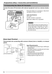
... AWG #22 to AWG #18 or equivalent Caution Due to external noise, the camera may not work properly even if the length of the cable is for connecting with...OUT Relay, switch etc. If this occurs, use a shielded cable or keep the cable away from the noise source. VN-C11 DC3.3V R Terminal 1 or 2 OUT 3.3V 0.6mA Sensor Connection Example 1 VCC R Input Requirements •...INPUT OUTPUT ALARM PUSH POWER MONITOR OUT 10BASE-T/100BASE-TX For USA DO NOT CONNECT TO THE TELEPHONE NETWORK Push Cable Specifications 50 m max. GND 16 Alarm Input Terminal This terminal is less than 50...
... AWG #22 to AWG #18 or equivalent Caution Due to external noise, the camera may not work properly even if the length of the cable is for connecting with...OUT Relay, switch etc. If this occurs, use a shielded cable or keep the cable away from the noise source. VN-C11 DC3.3V R Terminal 1 or 2 OUT 3.3V 0.6mA Sensor Connection Example 1 VCC R Input Requirements •...INPUT OUTPUT ALARM PUSH POWER MONITOR OUT 10BASE-T/100BASE-TX For USA DO NOT CONNECT TO THE TELEPHONE NETWORK Push Cable Specifications 50 m max. GND 16 Alarm Input Terminal This terminal is less than 50...
Instruction Manual
Page 19
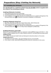
...the [V.Networks] icon is created in [Programs] of the Windows [Start] menu. [vn-c11u Setup Tool] is older, select [DX81NTeng.exe] and follow the instructions on the screen. 3. Installing V.Networks Setup Tool 1. Open the [JVC] ...JVC] folder. 2. If the installation is successfully executed, the [V.Networks] icon is created in [Programs] of the Windows [Start] menu. [V.Networks Controller] is displayed in the PC is supplied with VN-C11. Preparations (Step 2 Setting the Network) 2-1 Installing the Software For the operating VN-C11, install the software camera in [V.Networks...
...the [V.Networks] icon is created in [Programs] of the Windows [Start] menu. [vn-c11u Setup Tool] is older, select [DX81NTeng.exe] and follow the instructions on the screen. 3. Installing V.Networks Setup Tool 1. Open the [JVC] ...JVC] folder. 2. If the installation is successfully executed, the [V.Networks] icon is created in [Programs] of the Windows [Start] menu. [V.Networks Controller] is displayed in the PC is supplied with VN-C11. Preparations (Step 2 Setting the Network) 2-1 Installing the Software For the operating VN-C11, install the software camera in [V.Networks...

Instruction Manual
Page 20
...; Right-click [My Network] and select [Properties]. 2. Select the network connected to the PC by which VN-C11 is already known, skip 2-2 [Setting the PC's IP Address]. 1. With Windows XP, follow the procedure below to set the IP address of the PC by which the camera is operated. Preparations (...Step 2 Setting the Network) 2-2 Setting the...
...; Right-click [My Network] and select [Properties]. 2. Select the network connected to the PC by which VN-C11 is already known, skip 2-2 [Setting the PC's IP Address]. 1. With Windows XP, follow the procedure below to set the IP address of the PC by which the camera is operated. Preparations (...Step 2 Setting the Network) 2-2 Setting the...
Instruction Manual
Page 24
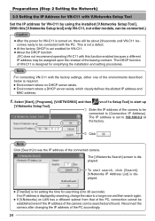
...], [V.NETWORKS] and then [vn-c11u Setup Tool] to see the IP address of the connected camera. Reconnect the camera after changing the IP address of the camera to be connected to [Connection IP Address]. The DHCP function of VN-C11 is set enabled for VN-C11. ● About the DHCP function JVC does not recommend operating VN-C11 with this [V.Networks...
...], [V.NETWORKS] and then [vn-c11u Setup Tool] to see the IP address of the connected camera. Reconnect the camera after changing the IP address of the camera to be connected to [Connection IP Address]. The DHCP function of VN-C11 is set enabled for VN-C11. ● About the DHCP function JVC does not recommend operating VN-C11 with this [V.Networks...
Instruction Manual
Page 25
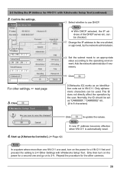
...can be used , turn on the power for a second one and go on the power for a VN-C11 first and proceed the setting to 2-4 Other Settings with V.Networks Setup Tool (continued) 2. Set the subnet mask to an appropriate value according to use DHCP. Normally...Setting the IP Address for VN-C11 with V.Networks Setup Tool. Click . [V.Networks ID] works as "CAM00001," "CAM00002" etc. (0 to 8 characters) Click to the one VN-C11 are used . Only then turn on to VN-C11. Ask the network administrator if necessary. For other cameras. 25 Only alphanumeric characters...
...can be used , turn on the power for a second one and go on the power for a VN-C11 first and proceed the setting to 2-4 Other Settings with V.Networks Setup Tool (continued) 2. Set the subnet mask to an appropriate value according to use DHCP. Normally...Setting the IP Address for VN-C11 with V.Networks Setup Tool. Click . [V.Networks ID] works as "CAM00001," "CAM00002" etc. (0 to 8 characters) Click to the one VN-C11 are used . Only then turn on to VN-C11. Ask the network administrator if necessary. For other cameras. 25 Only alphanumeric characters...

Instruction Manual
Page 42
... is required. • Environment where no DHCP server exists. • Environment where a DHCP server, which the camera is registered. Use a name that is displayed. Preparations (Step 2 Setting the Network) 2-5 Registering the Connected Camera with V.Networks Controller The connected camera can set whether VN-C11 automatically starts recording upon connection. You can be registered with the installed...
... is required. • Environment where no DHCP server exists. • Environment where a DHCP server, which the camera is registered. Use a name that is displayed. Preparations (Step 2 Setting the Network) 2-5 Registering the Connected Camera with V.Networks Controller The connected camera can set whether VN-C11 automatically starts recording upon connection. You can be registered with the installed...
Instruction Manual
Page 44
... be connected to connect. Live images from the camera are connected, the message "The VN-C11U has not start In the pull down menu, select the camera to VN-C1, VN-C2, VN-C3, VN-C30 (only for JPEG), VN- A1, VN-C10 and VN-C11. • In the MPEG4 mode, up [V.Networks Controller]. [V.Networks Controller] to start the Streaming Service." This is...
... be connected to connect. Live images from the camera are connected, the message "The VN-C11U has not start In the pull down menu, select the camera to VN-C1, VN-C2, VN-C3, VN-C30 (only for JPEG), VN- A1, VN-C10 and VN-C11. • In the MPEG4 mode, up [V.Networks Controller]. [V.Networks Controller] to start the Streaming Service." This is...

Instruction Manual
Page 46
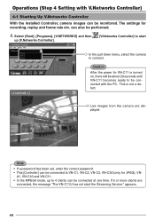
Click . Select the camera for which you wish to enable the motion detection function. Click . 46 Select [File] and then [Motion Detect Standby]. 2. Operations (Step 4 Setting with V.Networks Controller) 4-3 Motion Detection Standby With [V.Networks Controller] running, automatic connection will be activated upon reception of motion detection alert from VN-C11. 1. Select the camera. 3.
Click . Select the camera for which you wish to enable the motion detection function. Click . 46 Select [File] and then [Motion Detect Standby]. 2. Operations (Step 4 Setting with V.Networks Controller) 4-3 Motion Detection Standby With [V.Networks Controller] running, automatic connection will be activated upon reception of motion detection alert from VN-C11. 1. Select the camera. 3.

Instruction Manual
Page 55
...this is also possible to enlarge. 55 Operations (Step 5 Operations with V.Networks Controller) 5-1 Operations with V.Networks Controller [V.Networks Controller] can be used to select the camera, record and playback the camera images etc. (The Controller screens are identical with those for replaying a ... other V.Networks models. Stops recording. 6 SIZE Reduces the size of the [V.Networks Controller] screen. (See below.) Reduced screen 1 Camera Press here to select the camera using recorded files are not available for VN-C11.) 1 6 Not available for VN-C11. 2 34 5 1 Camera 4 REC...
...this is also possible to enlarge. 55 Operations (Step 5 Operations with V.Networks Controller) 5-1 Operations with V.Networks Controller [V.Networks Controller] can be used to select the camera, record and playback the camera images etc. (The Controller screens are identical with those for replaying a ... other V.Networks models. Stops recording. 6 SIZE Reduces the size of the [V.Networks Controller] screen. (See below.) Reduced screen 1 Camera Press here to select the camera using recorded files are not available for VN-C11.) 1 6 Not available for VN-C11. 2 34 5 1 Camera 4 REC...

Instruction Manual
Page 67
...to be accessed as the default page. The confirmation message, "Are you sure to RESET the camera to the authorization status. If there is entered correctly. 6-4 Settings with a security function for...pages Caution ● Password setting cannot be established appears. Note • Password Protection Function VN-C11 is equipped with a Web Browser (1. Do not forget the administrator password. ●... Effect Select [Available] to enable the Default Page function or [Not Available] to [V.Networks Setup Tool]. It is not required if the user and operator passwords are three access...
...to be accessed as the default page. The confirmation message, "Are you sure to RESET the camera to the authorization status. If there is entered correctly. 6-4 Settings with a security function for...pages Caution ● Password setting cannot be established appears. Note • Password Protection Function VN-C11 is equipped with a Web Browser (1. Do not forget the administrator password. ●... Effect Select [Available] to enable the Default Page function or [Not Available] to [V.Networks Setup Tool]. It is not required if the user and operator passwords are three access...

Instruction Manual
Page 76
...In the case that VN-C11 is being displayed, it exists. • Is the disk full? Unable to cancel an action. Check the network status. 76 Image size changes automatically. Check to see the IP addresses of all the cameras connected to VN-C11 cannot be established ...or fails. While "Now Connecting..." The coloration is loaded with [V.Networks Setup Tool]. Check the available memory capacity. • Once connection is activated, canceling...
...In the case that VN-C11 is being displayed, it exists. • Is the disk full? Unable to cancel an action. Check the network status. 76 Image size changes automatically. Check to see the IP addresses of all the cameras connected to VN-C11 cannot be established ...or fails. While "Now Connecting..." The coloration is loaded with [V.Networks Setup Tool]. Check the available memory capacity. • Once connection is activated, canceling...


