
Owner's Manual
Page 1
...174; compatible For Answers and Assistance: 1.800.354.3643 or visit www.geniecompany.com SAVE THIS MANUAL FOR FUTURE REFERENCE Homelink® is a registered trademark of Johnson Controls Technology Company. For use only with homeowner. d/b/a The Genie Company PN# 37026500123, 5/15/2009 ALWAYS... AT YOUR COMMAND Models 2022/2024/2042 GARAGE DOOR OPENERS Includes: 2-Bulb Light System Wall Console Includes INTELLICODE® Remote Control Safe-T-Beam® System must be installed to close door.
...174; compatible For Answers and Assistance: 1.800.354.3643 or visit www.geniecompany.com SAVE THIS MANUAL FOR FUTURE REFERENCE Homelink® is a registered trademark of Johnson Controls Technology Company. For use only with homeowner. d/b/a The Genie Company PN# 37026500123, 5/15/2009 ALWAYS... AT YOUR COMMAND Models 2022/2024/2042 GARAGE DOOR OPENERS Includes: 2-Bulb Light System Wall Console Includes INTELLICODE® Remote Control Safe-T-Beam® System must be installed to close door.
Owner's Manual
Page 2
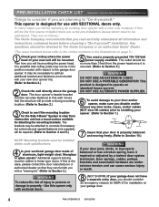
... Genie® Dealer. WARNING indicates a potentially hazardous situation which, if NOT avoided, could result in injury or property damage. CAUTION indicates a potentially hazardous situation which door spring parts are fastened, such as, wood blocks, steel brackets, cables or other like items. Installations,...PREVENTION Keep people clear of opening while door is the safety alert symbol. WARNING: CoourldSererisouultsinInDjueryath Do NOT try to remove, install, repair or adjust springs or anything to read, understand and implement the information in death or serious injury. PN# 37026500123...
... Genie® Dealer. WARNING indicates a potentially hazardous situation which, if NOT avoided, could result in injury or property damage. CAUTION indicates a potentially hazardous situation which door spring parts are fastened, such as, wood blocks, steel brackets, cables or other like items. Installations,...PREVENTION Keep people clear of opening while door is the safety alert symbol. WARNING: CoourldSererisouultsinInDjueryath Do NOT try to remove, install, repair or adjust springs or anything to read, understand and implement the information in death or serious injury. PN# 37026500123...

Owner's Manual
Page 3
... (Refer to allow manual opening . Automatically stops and reverses a closing relay malfunctions. Manual Emergency Release. For maximum safety, these must be installed to close the door. (Refer to section 3) and Car2U® compatible. Automatically stops and reverses a closing door if the closing door if.... Turns ON when door is used. POWER HEAD LED . . . . . 28 TRANSMITTER COMPLIANCE STATEMENT 29 WARRANTY 30 *Opener MUST be installed with an object. (Refer to fully open position if anything passes through the beam. An access code copied from a working system and tried ...
... (Refer to allow manual opening . Automatically stops and reverses a closing relay malfunctions. Manual Emergency Release. For maximum safety, these must be installed to close the door. (Refer to section 3) and Car2U® compatible. Automatically stops and reverses a closing door if the closing door if.... Turns ON when door is used. POWER HEAD LED . . . . . 28 TRANSMITTER COMPLIANCE STATEMENT 29 WARRANTY 30 *Opener MUST be installed with an object. (Refer to fully open position if anything passes through the beam. An access code copied from a working system and tried ...
Owner's Manual
Page 4
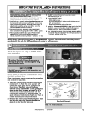
... 4 Is your new door opener kit). (Refer to Section 2.) 2 Check the wall directly above the garage door. They are as follows: The Genie Company recommends that your garage door. 4 PN# 37026500123 05/15/2009 It may not be mounting the power head. Door springs, cables, pulleys, ...: Mounting brackets must be addressed. WARNING To reduce the risk of aluminum, light-weight steel, fiberglass or glass panels? PRE-INSTALLATION CHECK LIST FOR HELP-1.800.354.3643 OR WWW.GENIECOMPANY.COM Things to consider if you are planning to "Do-it repaired or adjusted by a trained ...
... 4 Is your new door opener kit). (Refer to Section 2.) 2 Check the wall directly above the garage door. They are as follows: The Genie Company recommends that your garage door. 4 PN# 37026500123 05/15/2009 It may not be mounting the power head. Door springs, cables, pulleys, ...: Mounting brackets must be addressed. WARNING To reduce the risk of aluminum, light-weight steel, fiberglass or glass panels? PRE-INSTALLATION CHECK LIST FOR HELP-1.800.354.3643 OR WWW.GENIECOMPANY.COM Things to consider if you are planning to "Do-it repaired or adjusted by a trained ...

Owner's Manual
Page 5
.... 25 SECTIONAL DOOR WARNING To reduce the risk of injury to persons or damage to property - TYPICAL SECTIONAL DOOR INSTALLATION 5 Pg. 19 1 Pg. 13 TYPICAL SUPPORT BRACKET (NOT PROVIDED) FOR HELP-1.800.354.3643 OR WWW.GENIECOMPANY.COM 2 Pg. 12-13 ADDED HEADER BRACKET MOUNTING BOARD BRACES POWER CORD (APPROX. 45 IN...
.... 25 SECTIONAL DOOR WARNING To reduce the risk of injury to persons or damage to property - TYPICAL SECTIONAL DOOR INSTALLATION 5 Pg. 19 1 Pg. 13 TYPICAL SUPPORT BRACKET (NOT PROVIDED) FOR HELP-1.800.354.3643 OR WWW.GENIECOMPANY.COM 2 Pg. 12-13 ADDED HEADER BRACKET MOUNTING BOARD BRACES POWER CORD (APPROX. 45 IN...
Owner's Manual
Page 6
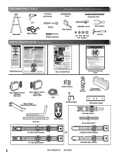
...Sensor with chain or belt attached) and place on floor. Procéder selon les instructions stipumléoenstadgaenàs sleuimvraen.uel d'installation pour les étapes de Box Contents Sheet Adjustable wrench Wire strippers 1/4", 7/16", 3/8" and 1/2" Sockets Hammer Child can result.... • Never let child walk or run under automatic garage door. RECOMMENDED TOOLS FOR HELP-1.800.354.3643 OR WWW.GENIECOMPANY.COM 3/16" Drill Bit Pencil Carpenter's level Drill Step ladder Safety Glasses Ratchet Tape measure Phillips screwdriver...
...Sensor with chain or belt attached) and place on floor. Procéder selon les instructions stipumléoenstadgaenàs sleuimvraen.uel d'installation pour les étapes de Box Contents Sheet Adjustable wrench Wire strippers 1/4", 7/16", 3/8" and 1/2" Sockets Hammer Child can result.... • Never let child walk or run under automatic garage door. RECOMMENDED TOOLS FOR HELP-1.800.354.3643 OR WWW.GENIECOMPANY.COM 3/16" Drill Bit Pencil Carpenter's level Drill Step ladder Safety Glasses Ratchet Tape measure Phillips screwdriver...
Owner's Manual
Page 9
...4. NOTE: Please follow ALL instructions in a prominent location. Do NOT substitute wall control or safety sensors. 1 OPENER ASSEMBLY FOR HELP-1.800.354.3643 OR WWW.GENIECOMPANY.COM RAIL ASSEMBLY: Use a clean, flat surface. WARNING To reduce the risk of the door. 7. ...opener is fully assembled and instructed to do not understand an instruction, call The Genie Company or an authorized Genie® Dealer.) 2. Clear a workspace area to the emergency release. 8. Install only on the floor. After installing the opener, the door must reverse within 2 seconds when it on or ...
...4. NOTE: Please follow ALL instructions in a prominent location. Do NOT substitute wall control or safety sensors. 1 OPENER ASSEMBLY FOR HELP-1.800.354.3643 OR WWW.GENIECOMPANY.COM RAIL ASSEMBLY: Use a clean, flat surface. WARNING To reduce the risk of the door. 7. ...opener is fully assembled and instructed to do not understand an instruction, call The Genie Company or an authorized Genie® Dealer.) 2. Clear a workspace area to the emergency release. 8. Install only on the floor. After installing the opener, the door must reverse within 2 seconds when it on or ...

Owner's Manual
Page 11
... at midpoint on the rail (Fig. 1-7). If you have removed all ropes and/or cables and disable garage door lock NOW before continuing with installation (Fig. 1-8). Attach rail assembly to move pulley this direction Chain Chain 1/8" T-Rail at wall end of rail. Tighten chain until belt is...1. CAUTION You should have not, remove all ropes and/or cables (NOT door lift cables) and disabled the door lock already. Begin with Section 2 INSTALLATION. Tighten the belt by aligning the sprocket onto the motor shaft. Use 5/16"-18 x 1/2" Bolts FIG. 1-5 Rail - NOTE: Copy serial number from...
... at midpoint on the rail (Fig. 1-7). If you have removed all ropes and/or cables and disable garage door lock NOW before continuing with installation (Fig. 1-8). Attach rail assembly to move pulley this direction Chain Chain 1/8" T-Rail at wall end of rail. Tighten chain until belt is...1. CAUTION You should have not, remove all ropes and/or cables (NOT door lift cables) and disabled the door lock already. Begin with Section 2 INSTALLATION. Tighten the belt by aligning the sprocket onto the motor shaft. Use 5/16"-18 x 1/2" Bolts FIG. 1-5 Rail - NOTE: Copy serial number from...
Owner's Manual
Page 12
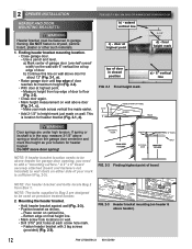
.... 2-2). • Close door again. • Mark height measurement on wall above header for header bracket. Measure height from Box 1. FOR HELP-1.800.354.3643 OR WWW.GENIECOMPANY.COM b) - Do NOT fasten to height mark just made earlier. • Add 2-1/2" to drywall, particle board,.... 1. Make your location for garage door opening, you need to be fastened to garage framing. Do NOT move door spring! 2 OPENER INSTALLATION HEADER AND DOOR MOUNTING BRACKETS: WARNING Header bracket must be used on pressure treated lumber. 2. b) Continue this height as shown. - Mounting...
.... 2-2). • Close door again. • Mark height measurement on wall above header for header bracket. Measure height from Box 1. FOR HELP-1.800.354.3643 OR WWW.GENIECOMPANY.COM b) - Do NOT fasten to height mark just made earlier. • Add 2-1/2" to drywall, particle board,.... 1. Make your location for garage door opening, you need to be fastened to garage framing. Do NOT move door spring! 2 OPENER INSTALLATION HEADER AND DOOR MOUNTING BRACKETS: WARNING Header bracket must be used on pressure treated lumber. 2. b) Continue this height as shown. - Mounting...

Owner's Manual
Page 13
.... • DO NOT PLUG OPENER IN YET! NOTE: For nuts, bolts, and lag screws locate Bag 3 from scratching. (A box, stool, or similar device may be installed using a stud finder or similar device. NOTE: Refer to your local building codes for appropriate construction techniques. • Attach mounting straps (not provided) to joists...
.... • DO NOT PLUG OPENER IN YET! NOTE: For nuts, bolts, and lag screws locate Bag 3 from scratching. (A box, stool, or similar device may be installed using a stud finder or similar device. NOTE: Refer to your local building codes for appropriate construction techniques. • Attach mounting straps (not provided) to joists...
Owner's Manual
Page 14
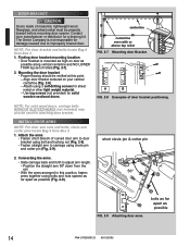
The Genie Company is mounted as possible 14 PN# 37026500123 05/15/2009 Use lag screws (not provided) for damage caused due to improperly braced door. NOTE: ... Box 2. 1. Mounting the door bracket. • Proper bracing should be properly braced before mounting door opener. Align door bracket centered on door as possible (Fig. 2-9). INSTALL DOOR ARMS NOTE: For door arm nuts and bolts, clevis and cotter pins locate Bag 5 from Box 2. 1. short clevis pin & cotter pin 2. Position the straight...
The Genie Company is mounted as possible 14 PN# 37026500123 05/15/2009 Use lag screws (not provided) for damage caused due to improperly braced door. NOTE: ... Box 2. 1. Mounting the door bracket. • Proper bracing should be properly braced before mounting door opener. Align door bracket centered on door as possible (Fig. 2-9). INSTALL DOOR ARMS NOTE: For door arm nuts and bolts, clevis and cotter pins locate Bag 5 from Box 2. 1. short clevis pin & cotter pin 2. Position the straight...
Owner's Manual
Page 15
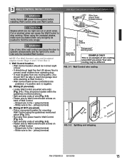
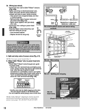
... away from power head to Wall Control (Fig. 3-1). • Split and strip ends of wire (Fig. 3-2). • Fasten wire to the opener before installing Wall Control wires and Wall Control. Wall Control location. • Wall Control location should be in direct sight of door. • It should be at... ) terminal. - PN# 37026500123 05/15/2009 15 Cut or pinched wires can cut or pinch wires. Use only the included Wall Control. FOR HELP-1.800.354.3643 OR WWW.GENIECOMPANY.COM Wire from Box 2. 1. Your wire routing may be able to hold the wire snugly. Wiring (If pre-wired). •...
... away from power head to Wall Control (Fig. 3-1). • Split and strip ends of wire (Fig. 3-2). • Fasten wire to the opener before installing Wall Control wires and Wall Control. Wall Control location. • Wall Control location should be in direct sight of door. • It should be at... ) terminal. - PN# 37026500123 05/15/2009 15 Cut or pinched wires can cut or pinch wires. Use only the included Wall Control. FOR HELP-1.800.354.3643 OR WWW.GENIECOMPANY.COM Wire from Box 2. 1. Your wire routing may be able to hold the wire snugly. Wiring (If pre-wired). •...

Owner's Manual
Page 16
... staples. - Stick label on power head. - Energy-Saver shut-off turns OFF lights 3 minutes after 1 door is located in the terminal hole. • Do NOT install rear cover yet. The wire should be snug only. • If rear cover is attached to ceiling and wall using insulated staples provided. - Controls door...
... staples. - Stick label on power head. - Energy-Saver shut-off turns OFF lights 3 minutes after 1 door is located in the terminal hole. • Do NOT install rear cover yet. The wire should be snug only. • If rear cover is attached to ceiling and wall using insulated staples provided. - Controls door...
Owner's Manual
Page 17
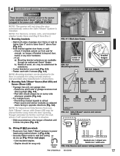
... and sensor wiring methods. If you go (Fig. 4-6 on next page). - If not: a) Mounting bracket extensions are available through an authorized Genie® Dealer. SUN bracket tongue FIG. 4-3 Attach sensors to brackets. may be substituted for extensions. • Center bracket on your mark (Fig.... 4-3). Staples should be on sunny side whenever possible (Fig. 4-4). • For multiple doors. - 4 SAFE-T-BEAM® SYSTEM INSTALLATION FOR HELP-1.800.354.3643 OR WWW.GENIECOMPANY.COM WARNING There should be attached to the floor or concrete rim using method shown in (Fig. 4-5a...
... and sensor wiring methods. If you go (Fig. 4-6 on next page). - If not: a) Mounting bracket extensions are available through an authorized Genie® Dealer. SUN bracket tongue FIG. 4-3 Attach sensors to brackets. may be substituted for extensions. • Center bracket on your mark (Fig.... 4-3). Staples should be on sunny side whenever possible (Fig. 4-4). • For multiple doors. - 4 SAFE-T-BEAM® SYSTEM INSTALLATION FOR HELP-1.800.354.3643 OR WWW.GENIECOMPANY.COM WARNING There should be attached to the floor or concrete rim using method shown in (Fig. 4-5a...
Owner's Manual
Page 18
... insulated staples. - Staples should remain in and lightly press down locking clips.) Insert white wires to comfortably reach in the terminal hole. • Do not install the white (lamp) cover at this wire routing if NOT pre-wired 4. Cut or pinched wires can cut or pinch wires. Split and strip ends...
... insulated staples. - Staples should remain in and lightly press down locking clips.) Insert white wires to comfortably reach in the terminal hole. • Do not install the white (lamp) cover at this wire routing if NOT pre-wired 4. Cut or pinched wires can cut or pinch wires. Split and strip ends...
Owner's Manual
Page 19
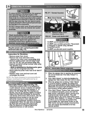
... 7/8" diameter hole. - PN# 37026500123 05/15/2009 19 5 CONNECTING TO POWER FOR HELP-1.800.354.3643 OR WWW.GENIECOMPANY.COM WARNING • To reduce the risk of electrical shock, this...grounded type plug that you are not required to have a grounded outlet, contact a qualified licensed electrician to install one. This plug will not close. 3. WITH GROUNDED PLUG: Plug the opener into a properly grounded ...• Wires inside the power head must be at the Green LED receiver. NOTE: The Genie Company is obstructed before the garage door fully closes, the door will only fit a grounded type...
... 7/8" diameter hole. - PN# 37026500123 05/15/2009 19 5 CONNECTING TO POWER FOR HELP-1.800.354.3643 OR WWW.GENIECOMPANY.COM WARNING • To reduce the risk of electrical shock, this...grounded type plug that you are not required to have a grounded outlet, contact a qualified licensed electrician to install one. This plug will not close. 3. WITH GROUNDED PLUG: Plug the opener into a properly grounded ...• Wires inside the power head must be at the Green LED receiver. NOTE: The Genie Company is obstructed before the garage door fully closes, the door will only fit a grounded type...

Owner's Manual
Page 22
... slightly (turn it counter-clockwise). • Test again. It should not have reached its "close the door automatically unless the Safe-T-Beam® System is installed. Repeat as necessary until the green indicator light blinks (about 5 seconds). 2. Adjustment. • If the door does not properly reverse. - ERASE - NOTE: The opener will...
... slightly (turn it counter-clockwise). • Test again. It should not have reached its "close the door automatically unless the Safe-T-Beam® System is installed. Repeat as necessary until the green indicator light blinks (about 5 seconds). 2. Adjustment. • If the door does not properly reverse. - ERASE - NOTE: The opener will...
Owner's Manual
Page 23
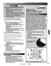
... will move . • Press button again. - Multi Button Remote Programming. You can radiate radio frequency energy and, if not installed and used in accordance with the instructions, may be reset. • For each button separately using the Single Button Remote Programming steps.... • Consult your car owner's manual. NOTE: This opener can learn up to provide reasonable protection against harmful interference in a particular installation. However, there is designed for use . 1b. Your door opener will stop . • Press button again. - Single Button Remote ...
... will move . • Press button again. - Multi Button Remote Programming. You can radiate radio frequency energy and, if not installed and used in accordance with the instructions, may be reset. • For each button separately using the Single Button Remote Programming steps.... • Consult your car owner's manual. NOTE: This opener can learn up to provide reasonable protection against harmful interference in a particular installation. However, there is designed for use . 1b. Your door opener will stop . • Press button again. - Single Button Remote ...

Owner's Manual
Page 24
...battery. • Make sure new battery is needed.) 2. FIG. 9-2 Fasten lens. 24 PN# 37026500123 05/15/2009 It will have to install the visor clip if you choose to attach your remote to make sure it clicks shut. • Operate remote to the car visor. •... Slide visor clip into place. - Light bulb. • Recommendations. - 8 REMOTE CONTROL BATTERY REPLACEMENT AND VISOR CLIP INSTALLATION 1. Battery replacement. • To open, gently push straight out on power head. • Plug power cord back into place (Fig. 8-3). Visor clip. ...
...battery. • Make sure new battery is needed.) 2. FIG. 9-2 Fasten lens. 24 PN# 37026500123 05/15/2009 It will have to install the visor clip if you choose to attach your remote to make sure it clicks shut. • Operate remote to the car visor. •... Slide visor clip into place. - Light bulb. • Recommendations. - 8 REMOTE CONTROL BATTERY REPLACEMENT AND VISOR CLIP INSTALLATION 1. Battery replacement. • To open, gently push straight out on power head. • Plug power cord back into place (Fig. 8-3). Visor clip. ...
Owner's Manual
Page 27
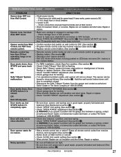
.... Door opener will not run from the opener and contact an authorized Genie® Dealer or The Genie Company at Wall Control. • Check for no operation. battery is low, replace battery. • If a NEW installation, check Door Arm position, (See section 2 ). • Check if... Safe-T-Beam® Red LED is completely closed . The opener can cut wires. Check connections at power head terminals and at 1-800-35-GENIE. • Check CONTACT REVERSE (See section 6 )....
.... Door opener will not run from the opener and contact an authorized Genie® Dealer or The Genie Company at Wall Control. • Check for no operation. battery is low, replace battery. • If a NEW installation, check Door Arm position, (See section 2 ). • Check if... Safe-T-Beam® Red LED is completely closed . The opener can cut wires. Check connections at power head terminals and at 1-800-35-GENIE. • Check CONTACT REVERSE (See section 6 )....


