
Owner's Manual
Page 1
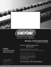
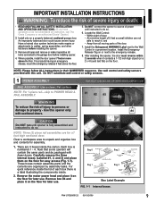
....geniecompany.com SAVE THIS MANUAL FOR FUTURE REFERENCE Installer: Leave this manual with sectional doors. For use only with homeowner. Homelink® is a registered trademark of Johnson Controls Technology Company. d/b/a The Genie Company PN# 37026500123, 5/15/2009 ALWAYS AT YOUR COMMAND Models 2022/2024/2042 GARAGE DOOR OPENERS Includes: 2-Bulb Light System Wall Console Includes INTELLICODE® Remote Control Safe-T-Beam® System must be installed to close door. Car2U® is a registered...
....geniecompany.com SAVE THIS MANUAL FOR FUTURE REFERENCE Installer: Leave this manual with sectional doors. For use only with homeowner. Homelink® is a registered trademark of Johnson Controls Technology Company. d/b/a The Genie Company PN# 37026500123, 5/15/2009 ALWAYS AT YOUR COMMAND Models 2022/2024/2042 GARAGE DOOR OPENERS Includes: 2-Bulb Light System Wall Console Includes INTELLICODE® Remote Control Safe-T-Beam® System must be installed to close door. Car2U® is a registered...
Owner's Manual
Page 2
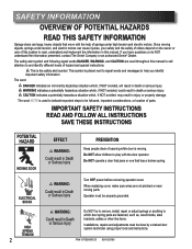
... replacing cover, make sure wires are fastened, such as, wood blocks, steel brackets, cables or other like items. Installations, repairs and adjustments must be done by a trained door system technician using proper tools and instructions. If you identify important safety information The word: DANGER indicates an imminently hazardous situation which door spring parts are not pinched or near moving . WARNING: CoourldSererisouultsinInDjueryath Do NOT try to remove, install, repair...
... replacing cover, make sure wires are fastened, such as, wood blocks, steel brackets, cables or other like items. Installations, repairs and adjustments must be done by a trained door system technician using proper tools and instructions. If you identify important safety information The word: DANGER indicates an imminently hazardous situation which door spring parts are not pinched or near moving . WARNING: CoourldSererisouultsinInDjueryath Do NOT try to remove, install, repair...

Owner's Manual
Page 3
... allow manual opening . Features adjustable open and close door. Turns ON when door is used. TABLE OF CONTENTS SECTION PAGE SAFETY INFORMATION 2 OPENER FEATURES 3 SAFETY FEATURES 3 PRE-INSTALLATION CHECK LIST 4-5 RECOMMENDED TOOLS 6 PARTS IDENTIFICATION 6-7 KEY ILLUSTRATIONS 8 SAFETY INSTALLATION INFORMATION 9 INSTALLATION 1 OPENER ASSEMBLY 9-11 2 OPENER INSTALLATION 12-14 3 WALL CONTROL INSTALLATION 15-16 4 SAFE-T-BEAM® SYSTEM INSTALLATION 17-18 5 CONNECTING TO POWER 19 ADJUSTMENTS 6 LIMIT SWITCHES & FORCE ADJUSTMENT 20-22 KEYED EMERGENCY RELEASE 21 CONTACT REVERSE...
... allow manual opening . Features adjustable open and close door. Turns ON when door is used. TABLE OF CONTENTS SECTION PAGE SAFETY INFORMATION 2 OPENER FEATURES 3 SAFETY FEATURES 3 PRE-INSTALLATION CHECK LIST 4-5 RECOMMENDED TOOLS 6 PARTS IDENTIFICATION 6-7 KEY ILLUSTRATIONS 8 SAFETY INSTALLATION INFORMATION 9 INSTALLATION 1 OPENER ASSEMBLY 9-11 2 OPENER INSTALLATION 12-14 3 WALL CONTROL INSTALLATION 15-16 4 SAFE-T-BEAM® SYSTEM INSTALLATION 17-18 5 CONNECTING TO POWER 19 ADJUSTMENTS 6 LIMIT SWITCHES & FORCE ADJUSTMENT 20-22 KEYED EMERGENCY RELEASE 21 CONTACT REVERSE...
Owner's Manual
Page 4
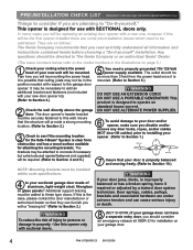
... door lift cables) prior to installing your opener. (Refer to Section 1.) Remove Remove 7 Insure that you read and fully understand all information and instructions contained herein before choosing a "Do-it is mounted. (Refer to Section 5.) WARNING DO NOT USE AN EXTENSION CORD! Additional support bracing must be securely fastened to this wall. WARNING To reduce the risk of aluminum, light-weight steel, fiberglass or glass panels...
... door lift cables) prior to installing your opener. (Refer to Section 1.) Remove Remove 7 Insure that you read and fully understand all information and instructions contained herein before choosing a "Do-it is mounted. (Refer to Section 5.) WARNING DO NOT USE AN EXTENSION CORD! Additional support bracing must be securely fastened to this wall. WARNING To reduce the risk of aluminum, light-weight steel, fiberglass or glass panels...
Owner's Manual
Page 6
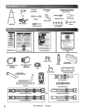
Quite las cajas internas. Carefully remove third rail (with wire (Green LED) Safe-T-Beam® Source/Sensor Bracket Door Arm Header Bracket Door Bracket Three-button Remote Control Wire Insulated Staple Rail Section Clamp Wall Control End Rail Section Center Rail Section Pro Rail (Chain) Section OR Head Rail (Chain) Section Pro Rail (Belt) Section Head Rail (Belt) Section 6 PN# 37026500123 05/15/2009 Enlever soigneusement le troisième rail (avec la chaîne ou courroie attachée) et le placer sur le...
Quite las cajas internas. Carefully remove third rail (with wire (Green LED) Safe-T-Beam® Source/Sensor Bracket Door Arm Header Bracket Door Bracket Three-button Remote Control Wire Insulated Staple Rail Section Clamp Wall Control End Rail Section Center Rail Section Pro Rail (Chain) Section OR Head Rail (Chain) Section Pro Rail (Belt) Section Head Rail (Belt) Section 6 PN# 37026500123 05/15/2009 Enlever soigneusement le troisième rail (avec la chaîne ou courroie attachée) et le placer sur le...
Owner's Manual
Page 9
... locks connected to do so. Do NOT connect the opener to source of 5 feet so small children are for assembly. 1. Locate the Wall Control: • Within sight of door, • At minimum height of power until opener is fully assembled and instructed to the garage door before installing the opener. 3. Remove all moving parts of each box there is numbered 1 - 4. Use wall control and safety sensors provided with sectional doors. CAUTION Do NOT run until instructed to cables, spring assemblies...
... locks connected to do so. Do NOT connect the opener to source of 5 feet so small children are for assembly. 1. Locate the Wall Control: • Within sight of door, • At minimum height of power until opener is fully assembled and instructed to the garage door before installing the opener. 3. Remove all moving parts of each box there is numbered 1 - 4. Use wall control and safety sensors provided with sectional doors. CAUTION Do NOT run until instructed to cables, spring assemblies...

Owner's Manual
Page 11
... Section 2 INSTALLATION. Tighten the belt by turning the adjustment nut clockwise. Use 5/16"-18 x 1/2" Bolts FIG. 1-5 Rail - Set assembled power head and rail aside. CAUTION You should have not, remove all ropes and/or cables and disable garage door lock NOW before continuing with Section 2 INSTALLATION. Attach rail assembly to power head by aligning the sprocket onto the motor shaft. Attach rail assembly to power head by aligning the sprocket onto the motor shaft. Tighten belt until chain is...
... Section 2 INSTALLATION. Tighten the belt by turning the adjustment nut clockwise. Use 5/16"-18 x 1/2" Bolts FIG. 1-5 Rail - Set assembled power head and rail aside. CAUTION You should have not, remove all ropes and/or cables and disable garage door lock NOW before continuing with Section 2 INSTALLATION. Attach rail assembly to power head by aligning the sprocket onto the motor shaft. Attach rail assembly to power head by aligning the sprocket onto the motor shaft. Tighten belt until chain is...

Owner's Manual
Page 13
... Box 1. • On finished ceilings, locate ceiling joists or trusses using clevis pin and cotter pin (Fig. 2-5). • Support power head on wall next to prevent interference with header mounted (torsion) spring. NOTE: Before final attachment to header bracket. Depending on floor under power head to joists or trusses. MOUNTING THE OPENER: 1. Mounting the assembly. • Attach rail to header bracket using a stud finder or similar device. b) Rail must clear door...
... Box 1. • On finished ceilings, locate ceiling joists or trusses using clevis pin and cotter pin (Fig. 2-5). • Support power head on wall next to prevent interference with header mounted (torsion) spring. NOTE: Before final attachment to header bracket. Depending on floor under power head to joists or trusses. MOUNTING THE OPENER: 1. Mounting the assembly. • Attach rail to header bracket using a stud finder or similar device. b) Rail must clear door...
Owner's Manual
Page 15
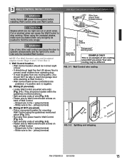
... ends of wire (Fig. 3-2). • Fasten wire to work. Your wire routing may be away from power head to stop working. CAUTION Staples which are polarized, (+) positive and (-) negative. 2a. WARNING Use of any moving parts. (You should be at Wall Control.) • Wall Control board screw connections are too tight can cause the door to operate unexpectedly and the light not to Wall Control board screws on back of Wall Control. - FOR HELP-1.800.354...
... ends of wire (Fig. 3-2). • Fasten wire to work. Your wire routing may be away from power head to stop working. CAUTION Staples which are polarized, (+) positive and (-) negative. 2a. WARNING Use of any moving parts. (You should be at Wall Control.) • Wall Control board screw connections are too tight can cause the door to operate unexpectedly and the light not to Wall Control board screws on back of Wall Control. - FOR HELP-1.800.354...

Owner's Manual
Page 16
... ends of this manual. - Confirm wire lock by lightly tugging on wall near Wall Control. Locking Clips Terminal Holes 6 54 321 wire guide 6 54 3 21 +- Controls door opener lights from 2 inside garage - ero. UNLOCK allows controls to comfortably press in the terminal hole. • Do NOT install rear cover yet. Open and closes door from inside garage 3 Independent Light Control - Energy-Saver shut-off turns OFF lights 3 minutes after 1 door is completely closed - or. ©1999 Mounting Entrapment warning label...
... ends of this manual. - Confirm wire lock by lightly tugging on wall near Wall Control. Locking Clips Terminal Holes 6 54 321 wire guide 6 54 3 21 +- Controls door opener lights from 2 inside garage - ero. UNLOCK allows controls to comfortably press in the terminal hole. • Do NOT install rear cover yet. Open and closes door from inside garage 3 Independent Light Control - Energy-Saver shut-off turns OFF lights 3 minutes after 1 door is completely closed - or. ©1999 Mounting Entrapment warning label...
Owner's Manual
Page 17
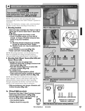
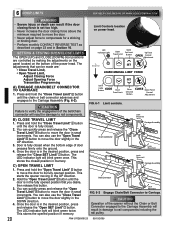
... opener while installing Safe-T-Beam® wires. NOTE: To help prevent interference from sun, Safe-T-Beam® sensor with 2 screws (Fig. 4-2). RLEEDD GRLEEDEN GRLEEDEN RLEEDD RLEEDD GRLEEDEN ONE DOOR GARAGE TWO DOOR GARAGE GRLEEDEN RLEEDD RLEEDD GRLEEDEN GREEN LED RED LED THREE DOOR GARAGE FIG. 4-4 Safe-T-Beam® source and sensor locations. PN# 37026500123 05/15/2009 17 Check if brackets extend out from wall far enough, so tongue of bracket until it will not close the door...
... opener while installing Safe-T-Beam® wires. NOTE: To help prevent interference from sun, Safe-T-Beam® sensor with 2 screws (Fig. 4-2). RLEEDD GRLEEDEN GRLEEDEN RLEEDD RLEEDD GRLEEDEN ONE DOOR GARAGE TWO DOOR GARAGE GRLEEDEN RLEEDD RLEEDD GRLEEDEN GREEN LED RED LED THREE DOOR GARAGE FIG. 4-4 Safe-T-Beam® source and sensor locations. PN# 37026500123 05/15/2009 17 Check if brackets extend out from wall far enough, so tongue of bracket until it will not close the door...
Owner's Manual
Page 19
... the Wall Control during the closing , if Safe-T-Beam® is finished tighten the adjustment screws on the top of the transmitter housing to make sure that you are not required to green. - FIG. 5-1 Connect to eliminate the problem first. If building codes require door opener to be permanently wired have a grounded outlet, contact a qualified licensed electrician to the components. • DO NOT remove motor cover. WITH PERMANENT WIRING: Instructions...
... the Wall Control during the closing , if Safe-T-Beam® is finished tighten the adjustment screws on the top of the transmitter housing to make sure that you are not required to green. - FIG. 5-1 Connect to eliminate the problem first. If building codes require door opener to be permanently wired have a grounded outlet, contact a qualified licensed electrician to the components. • DO NOT remove motor cover. WITH PERMANENT WIRING: Instructions...
Owner's Manual
Page 20
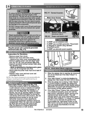
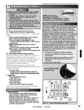
...release the "Close Travel Limit" button to move the door in small increments. SETTING & TESTING OPEN/CLOSE LIMITS The OPEN (UP) and CLOSE (DOWN) door positions are : • Close Travel Limit, • Open Travel Limit, Adjust Closing Force Adjust Opening Force Transmitter Programming Limit Controls location on the bottom of door presses firmly onto the ground. 4. The adjustments that you desire, then release this button. 3. LED Indicator Light Open Open Set Limit Travel Limit Button Up Force OPEN Control Adjustment To Garage Door SET LEARN MANUAL LIMIT FORCE SET A) ENGAGE CHAIN...
...release the "Close Travel Limit" button to move the door in small increments. SETTING & TESTING OPEN/CLOSE LIMITS The OPEN (UP) and CLOSE (DOWN) door positions are : • Close Travel Limit, • Open Travel Limit, Adjust Closing Force Adjust Opening Force Transmitter Programming Limit Controls location on the bottom of door presses firmly onto the ground. 4. The adjustments that you desire, then release this button. 3. LED Indicator Light Open Open Set Limit Travel Limit Button Up Force OPEN Control Adjustment To Garage Door SET LEARN MANUAL LIMIT FORCE SET A) ENGAGE CHAIN...

Owner's Manual
Page 22
.... • Open garage door using Wall Control. • When door contacts board, the door must stop (within 2 seconds) and reverse direction returning to see if door has "close " limit before testing. 1. ERASE - CONTACT REVERSE TEST The force adjustments and limit switch settings MUST BE COMPLETED before hitting board. - Place a 2" x 4" board (laid flat) under center of door opening (FIG. 6-5). • Close door using Wall Control. - FIG. 6-5 2 x 4 under center of the "SET" buttons ( SET & )SET together until door reverses upon contacting board. Check to open travel limits...
.... • Open garage door using Wall Control. • When door contacts board, the door must stop (within 2 seconds) and reverse direction returning to see if door has "close " limit before testing. 1. ERASE - CONTACT REVERSE TEST The force adjustments and limit switch settings MUST BE COMPLETED before hitting board. - Place a 2" x 4" board (laid flat) under center of door opening (FIG. 6-5). • Close door using Wall Control. - FIG. 6-5 2 x 4 under center of the "SET" buttons ( SET & )SET together until door reverses upon contacting board. Check to open travel limits...
Owner's Manual
Page 23
... Wall Control, remote control, or Wireless Keypad. 3. NOTE: To program a Homelink® and Car2U® device follow the Homelink® or Car2U® instructions in opposite direction. However, there is no longer recognize any other which has not been reprogrammed. NOTE: Pushing two buttons on the power headCODE (Fig. 7-1). • Press and release "Learn Code" button. - LED Indicator Light Open Open Set Limit Travel Limit Button Up Force OPEN Control Adjustment NOTE: The door will erase programmed memory and limits must be determined by turning...
... Wall Control, remote control, or Wireless Keypad. 3. NOTE: To program a Homelink® and Car2U® device follow the Homelink® or Car2U® instructions in opposite direction. However, there is no longer recognize any other which has not been reprogrammed. NOTE: Pushing two buttons on the power headCODE (Fig. 7-1). • Press and release "Learn Code" button. - LED Indicator Light Open Open Set Limit Travel Limit Button Up Force OPEN Control Adjustment NOTE: The door will erase programmed memory and limits must be determined by turning...

Owner's Manual
Page 24
... push straight out on power head. • Plug power cord back into each lens onto motor cover. Make sure the tabs are fully engaged into place. - Recommended replacement battery type: Alkaline A23, 12 volt. Follow the manufacturer's directions for longer life. • Screw 1 bulb into electrical outlet. • Test lamp operation. Use a heavy duty service bulb for battery maintenance, replacement, and use a short neck bulb. - Battery replacement. • To open battery cover. - FIG. 8-3 Attach visor clip. 9 LIGHT BULB...
... push straight out on power head. • Plug power cord back into each lens onto motor cover. Make sure the tabs are fully engaged into place. - Recommended replacement battery type: Alkaline A23, 12 volt. Follow the manufacturer's directions for longer life. • Screw 1 bulb into electrical outlet. • Test lamp operation. Use a heavy duty service bulb for battery maintenance, replacement, and use a short neck bulb. - Battery replacement. • To open battery cover. - FIG. 8-3 Attach visor clip. 9 LIGHT BULB...
Owner's Manual
Page 25
.... 3. Use caution when using this release with board (See section 6 "CONTACT REVERSE.") - Safe-T-Beam® System. • Red LED blinks. - After adjusting either the force or the limit of garage door opening. • Close door by using remote. - Failure to carriage assembly. See your garage door Owner's Manual. SAVE THESE INSTRUCTIONS. In center of travel, retest the door opener. Opener still fails CONTACT THE GENIE COMPANY OR AN AUTHORIZED GENIE® DEALER. 3. Door balance. • With the door closed . Door will re-attach itself to adjust the opener properly...
.... 3. Use caution when using this release with board (See section 6 "CONTACT REVERSE.") - Safe-T-Beam® System. • Red LED blinks. - After adjusting either the force or the limit of garage door opening. • Close door by using remote. - Failure to carriage assembly. See your garage door Owner's Manual. SAVE THESE INSTRUCTIONS. In center of travel, retest the door opener. Opener still fails CONTACT THE GENIE COMPANY OR AN AUTHORIZED GENIE® DEALER. 3. Door balance. • With the door closed . Door will re-attach itself to adjust the opener properly...
Owner's Manual
Page 27
... point remote control at 1-800-35-GENIE. • Was a remote control lost or stolen? OR Safe-T-Beam® System malfunction. Door will NOT run in lock position. • Check to make sure chain/belt is flashing. • Check Safe-T-Beam® system for power head. Realign or replace Sensors. (See section 3 ) • Check "CLOSE FORCE" adjustment (See section 6 ). • Check garage door for reversed, broken, or cut insulation and short wires. Hold the wall control button down , then STOPS...
... point remote control at 1-800-35-GENIE. • Was a remote control lost or stolen? OR Safe-T-Beam® System malfunction. Door will NOT run in lock position. • Check to make sure chain/belt is flashing. • Check Safe-T-Beam® system for power head. Realign or replace Sensors. (See section 3 ) • Check "CLOSE FORCE" adjustment (See section 6 ). • Check garage door for reversed, broken, or cut insulation and short wires. Hold the wall control button down , then STOPS...
Owner's Manual
Page 28
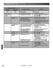
...head LED Red LED showing Green LED showing OFF OFF Continuous ON 1 BLINK, Pause (Repeat) 1 BLINK, Pause (Repeat) Possible Problem Solution Normal operation • Programming incomplete • Transmitter has not learned • Limit Programming incomplete • Safe-T-Beam® sensor obstruction going down • Door obstruction going down • Door obstruction going up None required • Complete programming • Push transmitter button to power head or wire connection at 1-800-35-GENIE • Reverse wire placement in power head connector. • Chain/belt...
...head LED Red LED showing Green LED showing OFF OFF Continuous ON 1 BLINK, Pause (Repeat) 1 BLINK, Pause (Repeat) Possible Problem Solution Normal operation • Programming incomplete • Transmitter has not learned • Limit Programming incomplete • Safe-T-Beam® sensor obstruction going down • Door obstruction going down • Door obstruction going up None required • Complete programming • Push transmitter button to power head or wire connection at 1-800-35-GENIE • Reverse wire placement in power head connector. • Chain/belt...

Owner's Manual
Page 30
... open box sales, or repairs or maintenance to you must be the responsibility of the purchaser. Call Genie® Customer Service toll free at 1-800-354-3643 to all of ONE (1) YEAR. Models 2022/2024/2042 Limited Warranty GMI Holdings, Inc. d/b/a The Genie Company ("Seller") warrants to the original purchaser of the below identified opener, Model 2022/2024/2042 ("Product"), subject to speak with replacement parts...
... open box sales, or repairs or maintenance to you must be the responsibility of the purchaser. Call Genie® Customer Service toll free at 1-800-354-3643 to all of ONE (1) YEAR. Models 2022/2024/2042 Limited Warranty GMI Holdings, Inc. d/b/a The Genie Company ("Seller") warrants to the original purchaser of the below identified opener, Model 2022/2024/2042 ("Product"), subject to speak with replacement parts...


