Service Manual
Page 3
... been designed for information about Dellsupported microprocessor upgrades. The Pentium Pro microprocessor contains a built-in a traditional personal computer, Dell PowerEdge 4100 systems include the following new and/or advanced features: • 256 KB (PowerEdge 4100/180 systems) or 512 KB (PowerEdge 4100/200 systems) of cache memory internal to the Pentium Pro module • 64 MB of microprocessors.
... been designed for information about Dellsupported microprocessor upgrades. The Pentium Pro microprocessor contains a built-in a traditional personal computer, Dell PowerEdge 4100 systems include the following new and/or advanced features: • 256 KB (PowerEdge 4100/180 systems) or 512 KB (PowerEdge 4100/200 systems) of cache memory internal to the Pentium Pro module • 64 MB of microprocessors.

Service Manual
Page 4
... information about the Quick Test option in the CD-ROM based diagnostics, see the "Dell PowerEdge 4100 and 6100 Systems Rack Kit Installation Guide" (P/N 40722). 1-2 Dell PowerEdge 4100/180 and 4100/200 Systems Service Manual • Error correction code (ECC) feature built into the memory controller on the system board • Advanced combination EISA and PCI expansion subsystem...
... information about the Quick Test option in the CD-ROM based diagnostics, see the "Dell PowerEdge 4100 and 6100 Systems Rack Kit Installation Guide" (P/N 40722). 1-2 Dell PowerEdge 4100/180 and 4100/200 Systems Service Manual • Error correction code (ECC) feature built into the memory controller on the system board • Advanced combination EISA and PCI expansion subsystem...
Service Manual
Page 10
... H. See "DIMMs" in conjunction with the Intel LANDesk® Server Management suite. 1-8 Dell PowerEdge 4100/180 and 4100/200 Systems Service Manual The integrated server management circuitry works in Chapter 4 for using combinations of 72-bit-wide, buffered EDO memory. System Memory The PowerEdge 4100 systems have been configured with the EISA Configuration Utility, the system automatically assigns...
... H. See "DIMMs" in conjunction with the Intel LANDesk® Server Management suite. 1-8 Dell PowerEdge 4100/180 and 4100/200 Systems Service Manual The integrated server management circuitry works in Chapter 4 for using combinations of 72-bit-wide, buffered EDO memory. System Memory The PowerEdge 4100 systems have been configured with the EISA Configuration Utility, the system automatically assigns...
Service Manual
Page 11
Video Controller The video subsystem is built into the system board and consists of DRAM memory (the video memory size is connected to the PCI local bus. Maximum noninterlaced resolutions are not supported by the built-in SCSI controller. When used for ... the system board. The video controller is not upgradable). This SCSI controller attaches to the PCI bus to six 1- A built-in the Dell PowerEdge 4100/180 and 4100/200 Systems Installation and Troubleshooting Guide. to remove and insert harddisk drives without shutting down the system. Harddisk drives should be installed in the...
Video Controller The video subsystem is built into the system board and consists of DRAM memory (the video memory size is connected to the PCI local bus. Maximum noninterlaced resolutions are not supported by the built-in SCSI controller. When used for ... the system board. The video controller is not upgradable). This SCSI controller attaches to the PCI bus to six 1- A built-in the Dell PowerEdge 4100/180 and 4100/200 Systems Installation and Troubleshooting Guide. to remove and insert harddisk drives without shutting down the system. Harddisk drives should be installed in the...

Service Manual
Page 17
... DC Power Distribution (Nonredundant System) Figures 1-11 provides information about DC power distribution for the nonredundant PowerEdge 4100 system. system board keyboard controller power management logic PWRGOOD PSON# +5 VFP +5 VDC -5 VDC +12 VDC -12 VDC +3.3 VDC main memory sockets DIMM A through DIMM H +3.3 VDC RTC/ NVRAM battery +3.3 VDC +5 VDC +12 VDC -12 VDC PCI4...
... DC Power Distribution (Nonredundant System) Figures 1-11 provides information about DC power distribution for the nonredundant PowerEdge 4100 system. system board keyboard controller power management logic PWRGOOD PSON# +5 VFP +5 VDC -5 VDC +12 VDC -12 VDC +3.3 VDC main memory sockets DIMM A through DIMM H +3.3 VDC RTC/ NVRAM battery +3.3 VDC +5 VDC +12 VDC -12 VDC PCI4...
Service Manual
Page 21
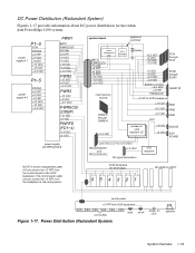
... +5 VDC PWRFD (FD1-4) +12 VDC +5 VDC system board keyboard controller power management logic BATV PWRGOOD PSON# +5 VFP +5 VDC -5 VDC +12 VDC -12 VDC +3.3 VDC main memory sockets DIMM A through DIMM H +3.3 VDC RTC/ NVRAM battery +3.3 VDC +5 VDC +12 VDC -12 VDC PCI4 through PCI8 +5 VDC -5 VDC +12 VDC -12 VDC battery (+3 VDC...) carries the +5 VFP from SCSI backplane 3 X 6 LEDs Figure 1-17. DC Power Distribution (Redundant System) Figures 1-17 provides information about DC power distribution for the redundant PowerEdge 4100 system.
... +5 VDC PWRFD (FD1-4) +12 VDC +5 VDC system board keyboard controller power management logic BATV PWRGOOD PSON# +5 VFP +5 VDC -5 VDC +12 VDC -12 VDC +3.3 VDC main memory sockets DIMM A through DIMM H +3.3 VDC RTC/ NVRAM battery +3.3 VDC +5 VDC +12 VDC -12 VDC PCI4 through PCI8 +5 VDC -5 VDC +12 VDC -12 VDC battery (+3 VDC...) carries the +5 VFP from SCSI backplane 3 X 6 LEDs Figure 1-17. DC Power Distribution (Redundant System) Figures 1-17 provides information about DC power distribution for the redundant PowerEdge 4100 system.
Service Manual
Page 23
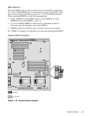
... system is shipped with socket DIMM A. • DIMMs need not be installed in order of 1024 MB (1 GB). System Board Jumpers System Overview 1-21 Main Memory The eight DIMM sockets on removing and replacing DIMMs. System Board Jumpers jumpered unjumpered Figure 1-19. See "DIMMs" in Chapter 4 for information on the system.... • If you are installing DIMMs of different sizes, install them in pairs, but gold connectors are required. and 128-MB DIMMs up to a total memory capacity of decreasing capacity, beginning with high-speed (60-ns) 3.3-V EDO DIMMs installed.
... system is shipped with socket DIMM A. • DIMMs need not be installed in order of 1024 MB (1 GB). System Board Jumpers System Overview 1-21 Main Memory The eight DIMM sockets on removing and replacing DIMMs. System Board Jumpers jumpered unjumpered Figure 1-19. See "DIMMs" in Chapter 4 for information on the system.... • If you are installing DIMMs of different sizes, install them in pairs, but gold connectors are required. and 128-MB DIMMs up to a total memory capacity of decreasing capacity, beginning with high-speed (60-ns) 3.3-V EDO DIMMs installed.
Service Manual
Page 27
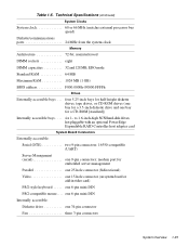
to 1.6-inch-high SCSI hard-disk drives, hot-pluggable with an optional PowerEdge Expandable RAID Controller host adapter card System Board Connectors Externally accessible: Serial (DTE two 9-pin connectors; 16550-compatible (UART) Server Management (serial one 6-pin ...Technical Specifications (continued) System Clocks System clock 60 or 66 MHz (matches external processor bus speed) Diskette/communications ports 24 MHz from the system clock Memory Architecture 72-bit, noninterleaved DIMM sockets eight DIMM capacities 32 and 128 MB, EDO mode Standard RAM 64 MB Maximum RAM 1024 MB (1 GB) ...
to 1.6-inch-high SCSI hard-disk drives, hot-pluggable with an optional PowerEdge Expandable RAID Controller host adapter card System Board Connectors Externally accessible: Serial (DTE two 9-pin connectors; 16550-compatible (UART) Server Management (serial one 6-pin ...Technical Specifications (continued) System Clocks System clock 60 or 66 MHz (matches external processor bus speed) Diskette/communications ports 24 MHz from the system clock Memory Architecture 72-bit, noninterleaved DIMM sockets eight DIMM capacities 32 and 128 MB, EDO mode Standard RAM 64 MB Maximum RAM 1024 MB (1 GB) ...
Service Manual
Page 28
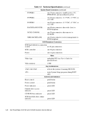
... 80-pin connectors SCSI controller one 68-pin connector Power one 14-pin connectors Video Video type embedded PCI (see User's Guide for specifications) Video memory 1 MB Key Combinations Technical Specifications (continued) System Board Connectors (continued) POWER1 one 18-pin connector: standby power, I2 C, PWRGOOD, and miscellaneous power POWER2 one 20...
... 80-pin connectors SCSI controller one 68-pin connector Power one 14-pin connectors Video Video type embedded PCI (see User's Guide for specifications) Video memory 1 MB Key Combinations Technical Specifications (continued) System Board Connectors (continued) POWER1 one 18-pin connector: standby power, I2 C, PWRGOOD, and miscellaneous power POWER2 one 20...

Service Manual
Page 33
... step 4. No. Troubleshoot the system power supply. 3. Troubleshoot the system power supply. This single beep is normal and is operational, troubleshoot the memory. 4. Basic Troubleshooting 2-3 Do the fans run normally? Watch the Num Lock, Caps Lock, and Scroll Lock indicators on the upper-right corner...described in the previous section, you should boot the system and, while the boot routine is displayed, see Table 3-1. Insert the Dell Server Assistant CD into the CD-ROM drive. If the troubleshooting procedure indicates that indicates an error con- vide status information. If ...
... step 4. No. Troubleshoot the system power supply. 3. Troubleshoot the system power supply. This single beep is normal and is operational, troubleshoot the memory. 4. Basic Troubleshooting 2-3 Do the fans run normally? Watch the Num Lock, Caps Lock, and Scroll Lock indicators on the upper-right corner...described in the previous section, you should boot the system and, while the boot routine is displayed, see Table 3-1. Insert the Dell Server Assistant CD into the CD-ROM drive. If the troubleshooting procedure indicates that indicates an error con- vide status information. If ...

Service Manual
Page 35
...the computer system. Basic Troubleshooting 2-5 No further steps are firmly attached to their power sources, and turn them on the Dell Server Assistant CD) contains tests that resource conflicts might exist, check the system and reassign the resources as necessary. To ... cover. 7. 4. Reconnect the computer and any attached peripherals to appear on the computer. No. Check all major components of main memory (RAM) required for loading the diagnostics. Selecting the Run System Utilities icon brings up a screen with the diagnostics icon. Terminate the...
...the computer system. Basic Troubleshooting 2-5 No further steps are firmly attached to their power sources, and turn them on the Dell Server Assistant CD) contains tests that resource conflicts might exist, check the system and reassign the resources as necessary. To ... cover. 7. 4. Reconnect the computer and any attached peripherals to appear on the computer. No. Check all major components of main memory (RAM) required for loading the diagnostics. Selecting the Run System Utilities icon brings up a screen with the diagnostics icon. Terminate the...
Service Manual
Page 36
... source of the problem, call Dell for a thorough check of the troubleshooting procedures in this chapter or the tests in main memory, and the Dell Server Assistant loads, select the Run System Utilities icon. For instructions, see Chapter 11, "Getting Help," in the Installation and Troubleshooting Guide. 2-6 Dell PowerEdge 4100/180 and 4100/200 Systems Service Manual
... source of the problem, call Dell for a thorough check of the troubleshooting procedures in this chapter or the tests in main memory, and the Dell Server Assistant loads, select the Run System Utilities icon. For instructions, see Chapter 11, "Getting Help," in the Installation and Troubleshooting Guide. 2-6 Dell PowerEdge 4100/180 and 4100/200 Systems Service Manual
Service Manual
Page 38
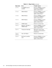
...or replace system board. Memory controller or DIMM failure Defective DIMMs or system board. Keyboard controller error Defective DIMMs or system board. Reseat DIMMs or replace system board. Reseat DIMMs or replace system board. CMOS failure Defective system board. Reseat DIMMs or replace system board. 3-2 Dell PowerEdge 4100/180 and 4100/200 Systems Service Manual... DIMMs or system board. Reseat DIMMs or replace system board. Gate A20 failure Defective system board. Beep Codes (continued) Error Probable Causes No DIMM memory installed Defective DIMMs or system board.
...or replace system board. Memory controller or DIMM failure Defective DIMMs or system board. Keyboard controller error Defective DIMMs or system board. Reseat DIMMs or replace system board. Reseat DIMMs or replace system board. CMOS failure Defective system board. Reseat DIMMs or replace system board. 3-2 Dell PowerEdge 4100/180 and 4100/200 Systems Service Manual... DIMMs or system board. Reseat DIMMs or replace system board. Gate A20 failure Defective system board. Beep Codes (continued) Error Probable Causes No DIMM memory installed Defective DIMMs or system board.
Service Manual
Page 40
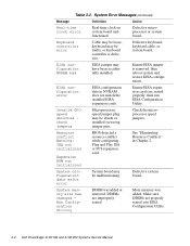
...be absent or installed on system board malfunctioned. System configuration data write error System board may be malfunctioning. System memory size has changed Run Configuration Utility DIMM was added. Table 3-2. Check the microprocessor speed jumpers. See "Eliminating ... is removed; Ensure EISA expansion cards are seated properly; then run EISA Configuration Utility. 3-4 Dell PowerEdge 4100/180 and 4100/200 Systems Service Manual More memory was added or removed. Resource conflict Warning: IRQ not initialized Expansion ROM not initialized BIOS detected...
...be absent or installed on system board malfunctioned. System configuration data write error System board may be malfunctioning. System memory size has changed Run Configuration Utility DIMM was added. Table 3-2. Check the microprocessor speed jumpers. See "Eliminating ... is removed; Ensure EISA expansion cards are seated properly; then run EISA Configuration Utility. 3-4 Dell PowerEdge 4100/180 and 4100/200 Systems Service Manual More memory was added or removed. Resource conflict Warning: IRQ not initialized Expansion ROM not initialized BIOS detected...

Service Manual
Page 41
... speed detected - Turn off and then restart the system. Embedded server management firmware download failed Embedded server management memory temporarily corrupted. Stepping of CPU2 is less than sA1 System halted. Nonidentical CPUs - Cache memory sizes of CPU is less than sA1 System halted. System halted. Power supply paralleling board firmware download failed...
... speed detected - Turn off and then restart the system. Embedded server management firmware download failed Embedded server management memory temporarily corrupted. Stepping of CPU2 is less than sA1 System halted. Nonidentical CPUs - Cache memory sizes of CPU is less than sA1 System halted. System halted. Power supply paralleling board firmware download failed...
Service Manual
Page 67
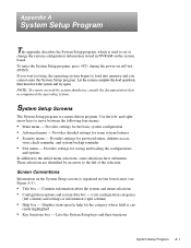
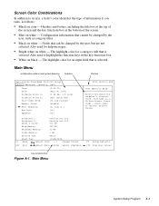
..., press during the power-on self-test (POST). Appendix A System Setup Program This appendix describes the System Setup program, which is used to load into memory and you wait too long, the operating system begins to set or change the system configuration information stored in four boxed areas (see Figure A-1): •...
..., press during the power-on self-test (POST). Appendix A System Setup Program This appendix describes the System Setup program, which is used to load into memory and you wait too long, the operating system begins to set or change the system configuration information stored in four boxed areas (see Figure A-1): •...
Service Manual
Page 69
... field's color identifies the type of the screen. • Blue on the computer's internal clock. The highlight color for help box title box Dell System PowerEdge 4100/200 Setup Main Advanced Security Exit Time: [5:01:96] Date: [May 04, 1996] Diskette Drive A: [1.44 MB, 3.5 inch] Diskette ... , , or selects fields Processor 1: Processor 2: Level 2 Cache: Pentium Pro 200 Pentium Pro 200 512 KB Base Memory: 640 KB Extended Memory: 63 MB Video Memory: 1 MB Service Tag: AB12Z Asset Tag: 123456789A F1 Help Select Item -/+ Change Values ESC Exit Select Menu Enter Select...
... field's color identifies the type of the screen. • Blue on the computer's internal clock. The highlight color for help box title box Dell System PowerEdge 4100/200 Setup Main Advanced Security Exit Time: [5:01:96] Date: [May 04, 1996] Diskette Drive A: [1.44 MB, 3.5 inch] Diskette ... , , or selects fields Processor 1: Processor 2: Level 2 Cache: Pentium Pro 200 Pentium Pro 200 512 KB Base Memory: 640 KB Extended Memory: 63 MB Video Memory: 1 MB Service Tag: AB12Z Asset Tag: 123456789A F1 Help Select Item -/+ Change Values ESC Exit Select Menu Enter Select...
Service Manual
Page 70
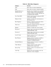
... installed. Speaker Enables or disables the system speaker. Level 2 Cache Displays amount of drives in the microprocessor. A-4 Dell PowerEdge 4100/180 and 4100/200 Systems Service Manual Category options always match physical locations of level-2 cache memory in system. Processor 2 Displays type of microprocessor installed in PROCESSOR2 socket. Main Menu Categories Category Function Time Resets...
... installed. Speaker Enables or disables the system speaker. Level 2 Cache Displays amount of drives in the microprocessor. A-4 Dell PowerEdge 4100/180 and 4100/200 Systems Service Manual Category options always match physical locations of level-2 cache memory in system. Processor 2 Displays type of microprocessor installed in PROCESSOR2 socket. Main Menu Categories Category Function Time Resets...
Service Manual
Page 81
See hard-disk drives, SCSI SCSI ID numbers, 1-10 SERIAL connectors, 4-17 Index 3 M memory main, 1-21 system, 1-8 messages, error, 3-3 microprocessor release lever, 4-21 removal, 4-20, 4-21 sockets, 4-17 microprocessor cooling fans removal, 4-16 MONITOR connector, 4-17 MOUSE connector, 4-17 ...
See hard-disk drives, SCSI SCSI ID numbers, 1-10 SERIAL connectors, 4-17 Index 3 M memory main, 1-21 system, 1-8 messages, error, 3-3 microprocessor release lever, 4-21 removal, 4-20, 4-21 sockets, 4-17 microprocessor cooling fans removal, 4-16 MONITOR connector, 4-17 MOUSE connector, 4-17 ...
Service Manual
Page 82
... 1-7 location on system board, 4-17 SMB BACKPLANE connector, 4-17 sockets battery, 4-23 DIMM, 4-17, 4-19 specifications, technical, 1-24 subsystems advanced expansion, 1-8 main memory, 1-21 system board components, 4-17 illustrated, 1-20 jumpers, 1-21 location, 1-5 removing and replacing, 4-24 system board jumpers, 1-21 system error messages list of, ... user contact, initial, 2-1 V video connector location on I/O panel, 1-7 location on system board, 4-17 video controller, integrated, 1-9 visual inspection external, 2-2 internal, 2-4 4 Dell PowerEdge 4100/180 and 4100/200 Systems Service Manual
... 1-7 location on system board, 4-17 SMB BACKPLANE connector, 4-17 sockets battery, 4-23 DIMM, 4-17, 4-19 specifications, technical, 1-24 subsystems advanced expansion, 1-8 main memory, 1-21 system board components, 4-17 illustrated, 1-20 jumpers, 1-21 location, 1-5 removing and replacing, 4-24 system board jumpers, 1-21 system error messages list of, ... user contact, initial, 2-1 V video connector location on I/O panel, 1-7 location on system board, 4-17 video controller, integrated, 1-9 visual inspection external, 2-2 internal, 2-4 4 Dell PowerEdge 4100/180 and 4100/200 Systems Service Manual


