Service Manual
Page 3
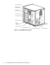
.... These buses are as the extended industry-standard architecture (EISA) expansion bus. PowerEdge 4100 systems incorporate the high-performance peripheral component interconnect (PCI) local bus as well as follows: • Dell PowerEdge 4100/180 system - 180 MHz derived from a system clock frequency of 60 MHz • Dell PowerEdge 4100/200 system - 200 MHz derived from a system clock frequency of 66...
.... These buses are as the extended industry-standard architecture (EISA) expansion bus. PowerEdge 4100 systems incorporate the high-performance peripheral component interconnect (PCI) local bus as well as follows: • Dell PowerEdge 4100/180 system - 180 MHz derived from a system clock frequency of 60 MHz • Dell PowerEdge 4100/200 system - 200 MHz derived from a system clock frequency of 66...

Service Manual
Page 4
... • New quick-test feature in the system diagnostics All of system features, see the "Dell PowerEdge 4100 and 6100 Systems Rack Kit Installation Guide" (P/N 40722). 1-2 Dell PowerEdge 4100/180 and 4100/200 Systems Service Manual • Error correction code (ECC) feature built into the memory controller ... list of these features, except the new quick-test feature, are briefly described in this chapter. For information about installing the PowerEdge 4100 systems in a rack, see "Technical Specifications" found later in this chapter. (For more information about the Quick Test option ...
... • New quick-test feature in the system diagnostics All of system features, see the "Dell PowerEdge 4100 and 6100 Systems Rack Kit Installation Guide" (P/N 40722). 1-2 Dell PowerEdge 4100/180 and 4100/200 Systems Service Manual • Error correction code (ECC) feature built into the memory controller ... list of these features, except the new quick-test feature, are briefly described in this chapter. For information about installing the PowerEdge 4100 systems in a rack, see "Technical Specifications" found later in this chapter. (For more information about the Quick Test option ...

Service Manual
Page 6
... Features SCSI hard-disk drive activity indicator CAUTION: To avoid possible data or file structure corruptions, the frontpanel reset button should be rebooted by pressing . 1-4 Dell PowerEdge 4100/180 and 4100/200 Systems Service Manual If you are using the reset button to initiate a hardware reset, close any open application programs and files if possible.
... Features SCSI hard-disk drive activity indicator CAUTION: To avoid possible data or file structure corruptions, the frontpanel reset button should be rebooted by pressing . 1-4 Dell PowerEdge 4100/180 and 4100/200 Systems Service Manual If you are using the reset button to initiate a hardware reset, close any open application programs and files if possible.
Service Manual
Page 8
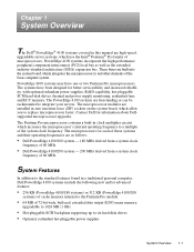
external drive bays (4) diskette interface cable (ultra-narrow) SCSI interface connector (ultra-wide) internal drive bays (6) SCSI backplane board SCSI power connector server management connector control panel connector power supply (optional) power supply SMB connector Figure 1-4. Back/Right Internal View SCSI connector port 1-6 Dell PowerEdge 4100/180 and 4100/200 Systems Service Manual
external drive bays (4) diskette interface cable (ultra-narrow) SCSI interface connector (ultra-wide) internal drive bays (6) SCSI backplane board SCSI power connector server management connector control panel connector power supply (optional) power supply SMB connector Figure 1-4. Back/Right Internal View SCSI connector port 1-6 Dell PowerEdge 4100/180 and 4100/200 Systems Service Manual
Service Manual
Page 10
... it to guarantee compatibility. The EISA Configuration Utility, included with the Intel LANDesk® Server Management suite. 1-8 Dell PowerEdge 4100/180 and 4100/200 Systems Service Manual The eight expansion-card slots include three EISA expansion-card connectors and five PCI expansion-card ...connectors. The integrated server management circuitry works in the Dell PowerEdge 4100/180 and 4100/200 Systems User's Guide describes the EISA Configuration Utility and provides instructions for information on the system board ...
... it to guarantee compatibility. The EISA Configuration Utility, included with the Intel LANDesk® Server Management suite. 1-8 Dell PowerEdge 4100/180 and 4100/200 Systems Service Manual The eight expansion-card slots include three EISA expansion-card connectors and five PCI expansion-card ...connectors. The integrated server management circuitry works in the Dell PowerEdge 4100/180 and 4100/200 Systems User's Guide describes the EISA Configuration Utility and provides instructions for information on the system board ...
Service Manual
Page 11
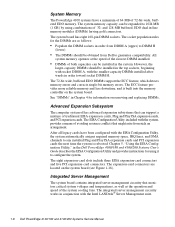
In the standard Dell PowerEdge 4100 system configuration, the Ultra/Wide SCSI host adapter on the... 16.7 million colors, 800 x 600 pixels with 65,536 colors, and 1024 x 768 pixels with an optional PowerEdge Expandable RAID Controller host adapter card, the SCSI backplane board allows you to six 1- System Overview 1-9 The video ...either fast/wide or ultra [fast] wide). Dell supports the drives it furnishes. SCSI Hard-Disk Drives Six internal hot-pluggable hard-disk drive bays are normally used in the Dell PowerEdge 4100/180 and 4100/200 Systems Installation and Troubleshooting Guide.
In the standard Dell PowerEdge 4100 system configuration, the Ultra/Wide SCSI host adapter on the... 16.7 million colors, 800 x 600 pixels with 65,536 colors, and 1024 x 768 pixels with an optional PowerEdge Expandable RAID Controller host adapter card, the SCSI backplane board allows you to six 1- System Overview 1-9 The video ...either fast/wide or ultra [fast] wide). Dell supports the drives it furnishes. SCSI Hard-Disk Drives Six internal hot-pluggable hard-disk drive bays are normally used in the Dell PowerEdge 4100/180 and 4100/200 Systems Installation and Troubleshooting Guide.
Service Manual
Page 12
.... NOTE: There is configured as follows: - Therefore, any additional devices attached to the cable should have a unique SCSI ID number from Dell, the default SCSI ID numbers are assigned as follows: • The computer's built-in Ultra/Narrow SCSI host adapter is configured through the... the devices to the end connector on the SCSI cable, and leave the terminator enabled on disabling the device's terminator. 1-10 Dell PowerEdge 4100/180 and 4100/200 Systems Service Manual See the documentation provided with the SCSI device for all other end of the SCSI cable connects to the ...
.... NOTE: There is configured as follows: - Therefore, any additional devices attached to the cable should have a unique SCSI ID number from Dell, the default SCSI ID numbers are assigned as follows: • The computer's built-in Ultra/Narrow SCSI host adapter is configured through the... the devices to the end connector on the SCSI cable, and leave the terminator enabled on disabling the device's terminator. 1-10 Dell PowerEdge 4100/180 and 4100/200 Systems Service Manual See the documentation provided with the SCSI device for all other end of the SCSI cable connects to the ...
Service Manual
Page 14
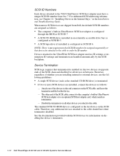
P2 P1 P5 P4 P3 Figure 1-6. Power Connector Panel 1-12 Dell PowerEdge 4100/180 and 4100/200 Systems Service Manual Power Supply Connectors J12 (P2) J11 (P1) J15 (P5) J14 (P4) J13 (P3) Figure 1-7. Pin Assignments for the DC Power Connectors (Nonredundant Systems) The power-supply output voltages for nonredundant systems can be measured at the connectors on the back of connectors. The following illustrations show both sets of the power supply (P1, P2, P3, P4, and P5) or at the connectors on the power connector panel (J11, J12, J13, J14, and J15).
P2 P1 P5 P4 P3 Figure 1-6. Power Connector Panel 1-12 Dell PowerEdge 4100/180 and 4100/200 Systems Service Manual Power Supply Connectors J12 (P2) J11 (P1) J15 (P5) J14 (P4) J13 (P3) Figure 1-7. Pin Assignments for the DC Power Connectors (Nonredundant Systems) The power-supply output voltages for nonredundant systems can be measured at the connectors on the back of connectors. The following illustrations show both sets of the power supply (P1, P2, P3, P4, and P5) or at the connectors on the power connector panel (J11, J12, J13, J14, and J15).
Service Manual
Page 16
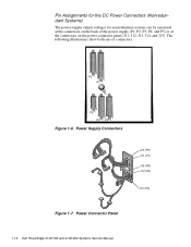
... (orange) +12 VDC (yellow) +5 VDC (red) +5 VDC (red) +3.3 VDC (orange) +12 VDC (yellow) +3.3 VDC (orange) +5 VDC (red) Figure 1-9. DC Power Connector J15 (P5) 1-14 Dell PowerEdge 4100/180 and 4100/200 Systems Service Manual DC Power Connectors J12 (P2), J13 (P3), and J14 (P4) J15 (P5) +SW1 +12 VDC (red) +3.3 VDC (orange) Fail LED cathode...
... (orange) +12 VDC (yellow) +5 VDC (red) +5 VDC (red) +3.3 VDC (orange) +12 VDC (yellow) +3.3 VDC (orange) +5 VDC (red) Figure 1-9. DC Power Connector J15 (P5) 1-14 Dell PowerEdge 4100/180 and 4100/200 Systems Service Manual DC Power Connectors J12 (P2), J13 (P3), and J14 (P4) J15 (P5) +SW1 +12 VDC (red) +3.3 VDC (orange) Fail LED cathode...
Service Manual
Page 18
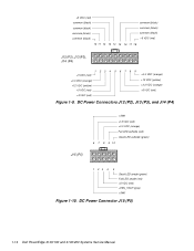
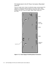
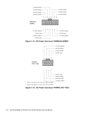
Pin Assignments for the DC Power Connectors (Redundant Systems) The power-supply output voltages for redundant systems can be measured at the connectors on the power-supply paralleling board (PWR1, PWR2, PWR3, PWRSCSI, and PWRFD) or at the connectors on the end of the wire bundles extending from these connectors (PWR1, PWR2, PWR3, DDBP, and FD1-FD4). Power-Supply Paralleling Board Connectors 1-16 Dell PowerEdge 4100/180 and 4100/200 Systems Service Manual PWR1 PWRFD (FD1-FD4) PWR2 diagnostics port PWR3 PWRSCSI (DDBP) Figure 1-12.
Pin Assignments for the DC Power Connectors (Redundant Systems) The power-supply output voltages for redundant systems can be measured at the connectors on the power-supply paralleling board (PWR1, PWR2, PWR3, PWRSCSI, and PWRFD) or at the connectors on the end of the wire bundles extending from these connectors (PWR1, PWR2, PWR3, DDBP, and FD1-FD4). Power-Supply Paralleling Board Connectors 1-16 Dell PowerEdge 4100/180 and 4100/200 Systems Service Manual PWR1 PWRFD (FD1-FD4) PWR2 diagnostics port PWR3 PWRSCSI (DDBP) Figure 1-12.
Service Manual
Page 20
...) +5 VDC (red) +12 VDC (yellow) +5 VDC (red) 567 +12 VDC (yellow) +5 VDC (red) +12 VDC (yellow) Figure 1-15. DC Power Connector PWRFD (FD1-FD4) 1-18 Dell PowerEdge 4100/180 and 4100/200 Systems Service Manual
...) +5 VDC (red) +12 VDC (yellow) +5 VDC (red) 567 +12 VDC (yellow) +5 VDC (red) +12 VDC (yellow) Figure 1-15. DC Power Connector PWRFD (FD1-FD4) 1-18 Dell PowerEdge 4100/180 and 4100/200 Systems Service Manual
Service Manual
Page 22
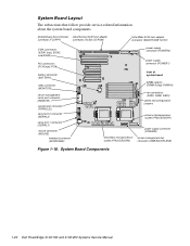
...) connector (SMB BACKPLANE) Figure 1-18. System Board Layout The subsections that follow provide service-related information about the system board components. System Board Components 1-20 Dell PowerEdge 4100/180 and 4100/200 Systems Service Manual
...) connector (SMB BACKPLANE) Figure 1-18. System Board Layout The subsections that follow provide service-related information about the system board components. System Board Components 1-20 Dell PowerEdge 4100/180 and 4100/200 Systems Service Manual

Service Manual
Page 24
...Configuration Utility Not installed (utility settings are retained at system boot) VGA Integrated video controller Installed (controller is 180 MHz Interrupt Assignments Table 1-3. Interrupt Assignments IRQ Line Used/Available IRQ0 Generated by system timer IRQ1 Generated by ... controller to indicate that device connected to indicate that diskette drive requires service IRQ7 Generated by expansion card 1-22 Dell PowerEdge 4100/180 and 4100/200 Systems Service Manual do not change ) 200MHZ Microprocessor speed Installed only if the microprocessor's internal speed is...
...Configuration Utility Not installed (utility settings are retained at system boot) VGA Integrated video controller Installed (controller is 180 MHz Interrupt Assignments Table 1-3. Interrupt Assignments IRQ Line Used/Available IRQ0 Generated by system timer IRQ1 Generated by ... controller to indicate that device connected to indicate that diskette drive requires service IRQ7 Generated by expansion card 1-22 Dell PowerEdge 4100/180 and 4100/200 Systems Service Manual do not change ) 200MHZ Microprocessor speed Installed only if the microprocessor's internal speed is...
Service Manual
Page 26
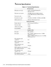
... expansion-card connector data width (maximum 32 bits PCI expansion-card connector size 120 pins PCI expansion-card connector data width (maximum 32 bits 1-24 Dell PowerEdge 4100/180 and 4100/200 Systems Service Manual Technical Specifications Table 1-5.
... expansion-card connector data width (maximum 32 bits PCI expansion-card connector size 120 pins PCI expansion-card connector data width (maximum 32 bits 1-24 Dell PowerEdge 4100/180 and 4100/200 Systems Service Manual Technical Specifications Table 1-5.
Service Manual
Page 28
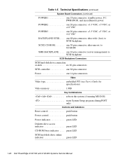
Technical Specifications (continued) System Board Connectors (continued) POWER1 one 18-pin connector: standby power, I2 C, PWRGOOD, and miscellaneous power POWER2 one 20-pin connector: +3.3 VDC, +5 VDC, or +12 VDC POWER3 one 14-pin connectors Video Video type embedded PCI (see User's Guide for specifications) Video memory 1 MB Key Combinations one 16-pin connector (server management) to CD-ROM SMB BACKPLANE. . . . . one 68-pin connector, ultra-wide (fast), to SCSI backplane SCSI2 CD-ROM one 50-pin connector, ultra-narrow, to SCSI backplane SCSI Backplane Connectors SCSI hard-disk ...
Technical Specifications (continued) System Board Connectors (continued) POWER1 one 18-pin connector: standby power, I2 C, PWRGOOD, and miscellaneous power POWER2 one 20-pin connector: +3.3 VDC, +5 VDC, or +12 VDC POWER3 one 14-pin connectors Video Video type embedded PCI (see User's Guide for specifications) Video memory 1 MB Key Combinations one 16-pin connector (server management) to CD-ROM SMB BACKPLANE. . . . . one 68-pin connector, ultra-wide (fast), to SCSI backplane SCSI2 CD-ROM one 50-pin connector, ultra-narrow, to SCSI backplane SCSI Backplane Connectors SCSI hard-disk ...
Service Manual
Page 30
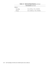
Technical Specifications (continued) Environmental (continued) Altitude: Operating 16 to 3048 m (-50 to 10,000 ft) Storage 16 to 10,600 m (-50 to 35,000 ft) z 1-28 Dell PowerEdge 4100/180 and 4100/200 Systems Service Manual Table 1-5.
Technical Specifications (continued) Environmental (continued) Altitude: Operating 16 to 3048 m (-50 to 10,000 ft) Storage 16 to 10,600 m (-50 to 35,000 ft) z 1-28 Dell PowerEdge 4100/180 and 4100/200 Systems Service Manual Table 1-5.
Service Manual
Page 32
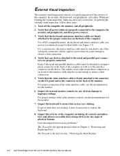
... cables. For proper settings of the video monitor controls, see the documentation for the monitor. 6. Proceed to the next section, "Observing the Boot Routine." 2-2 Dell PowerEdge 4100/180 and 4100/200 Systems Service Manual External Visual Inspection The external visual inspection consists of a quick inspection of the exterior of the computer, the monitor, the keyboard...
... cables. For proper settings of the video monitor controls, see the documentation for the monitor. 6. Proceed to the next section, "Observing the Boot Routine." 2-2 Dell PowerEdge 4100/180 and 4100/200 Systems Service Manual External Visual Inspection The external visual inspection consists of a quick inspection of the exterior of the computer, the monitor, the keyboard...
Service Manual
Page 34
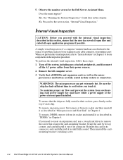
...push it as a loose expansion card, cable connector, or mounting screw. Then reinstall the cardmounting bracket's retaining screw. 2-4 Dell PowerEdge 4100/180 and 4100/200 Systems Service Manual See "Running the System Diagnostics" found later in this section, ensure that all open application programs if...of a problem, such as described in "Microprocessor and Heat Sink" in their power sources. 2. 5. Observe the monitor screen for the Dell Server Assistant Menu. To perform the internal visual inspection, follow these steps: 1. Proceed to the source of a computer's interior hardware ...
...push it as a loose expansion card, cable connector, or mounting screw. Then reinstall the cardmounting bracket's retaining screw. 2-4 Dell PowerEdge 4100/180 and 4100/200 Systems Service Manual See "Running the System Diagnostics" found later in this section, ensure that all open application programs if...of a problem, such as described in "Microprocessor and Heat Sink" in their power sources. 2. 5. Observe the monitor screen for the Dell Server Assistant Menu. To perform the internal visual inspection, follow these steps: 1. Proceed to the source of a computer's interior hardware ...
Service Manual
Page 36
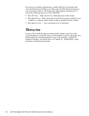
If no errors are found in the Installation and Troubleshooting Guide. 2-6 Dell PowerEdge 4100/180 and 4100/200 Systems Service Manual For instructions, see Chapter 11, "Getting Help," in main memory, and the Dell Server Assistant loads, select the Run System Utilities icon. Runs selected tests from all tests for ...system diagnostics reveals the source of the problem or leads to the proper troubleshooting steps for determining the source of the problem, call Dell for a thorough check of the system • Run Quick Tests - The Diagnostics Menu appears, allowing you to choose the ...
If no errors are found in the Installation and Troubleshooting Guide. 2-6 Dell PowerEdge 4100/180 and 4100/200 Systems Service Manual For instructions, see Chapter 11, "Getting Help," in main memory, and the Dell Server Assistant loads, select the Run System Utilities icon. Runs selected tests from all tests for ...system diagnostics reveals the source of the problem or leads to the proper troubleshooting steps for determining the source of the problem, call Dell for a thorough check of the system • Run Quick Tests - The Diagnostics Menu appears, allowing you to choose the ...
Service Manual
Page 38
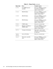
... or replace system board. DRAM failure Defective DIMMs or system board. DRAM failure Defective DIMMs or system board. Reseat DIMMs or replace system board. 3-2 Dell PowerEdge 4100/180 and 4100/200 Systems Service Manual Reseat DIMMs or replace system board. Reseat DIMMs or replace system board. DRAM failure Defective DIMMs or system board. Beep Code...
... or replace system board. DRAM failure Defective DIMMs or system board. DRAM failure Defective DIMMs or system board. Reseat DIMMs or replace system board. 3-2 Dell PowerEdge 4100/180 and 4100/200 Systems Service Manual Reseat DIMMs or replace system board. Reseat DIMMs or replace system board. DRAM failure Defective DIMMs or system board. Beep Code...
