
Service Manual
Page 4
... these features, except the new quick-test feature, are briefly described in this chapter. (For more information about installing the PowerEdge 4100 systems in a rack, see "Technical Specifications" found later in this chapter. For information about the Quick Test option in the CD-ROM based diagnostics, see "Running...operation of the system cooling fans • CD-ROM drive standard in Chapter 2.) For a complete list of system features, see the "Dell PowerEdge 4100 and 6100 Systems Rack Kit Installation Guide" (P/N 40722). 1-2 Dell PowerEdge 4100/180 and 4100/200 Systems Service Manual
... these features, except the new quick-test feature, are briefly described in this chapter. (For more information about installing the PowerEdge 4100 systems in a rack, see "Technical Specifications" found later in this chapter. For information about the Quick Test option in the CD-ROM based diagnostics, see "Running...operation of the system cooling fans • CD-ROM drive standard in Chapter 2.) For a complete list of system features, see the "Dell PowerEdge 4100 and 6100 Systems Rack Kit Installation Guide" (P/N 40722). 1-2 Dell PowerEdge 4100/180 and 4100/200 Systems Service Manual
Service Manual
Page 26
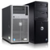
Technical Specifications Table 1-5. EISA: 7.5 MHz (180/60 processor); 8.33 MHz (200/66 processor) PCI expansion-card connectors five EISA expansion-card connectors three EISA expansion-card connector ... width (maximum 32 bits PCI expansion-card connector size 120 pins PCI expansion-card connector data width (maximum 32 bits 1-24 Dell PowerEdge 4100/180 and 4100/200 Systems Service Manual Technical Specifications Microprocessor Microprocessor type single or dual Intel Pentium Pro microprocessors Microprocessor speed 200 MHz internal (66 MHz external) or 180 MHz internal...
Technical Specifications Table 1-5. EISA: 7.5 MHz (180/60 processor); 8.33 MHz (200/66 processor) PCI expansion-card connectors five EISA expansion-card connectors three EISA expansion-card connector ... width (maximum 32 bits PCI expansion-card connector size 120 pins PCI expansion-card connector data width (maximum 32 bits 1-24 Dell PowerEdge 4100/180 and 4100/200 Systems Service Manual Technical Specifications Microprocessor Microprocessor type single or dual Intel Pentium Pro microprocessors Microprocessor speed 200 MHz internal (66 MHz external) or 180 MHz internal...
Service Manual
Page 27
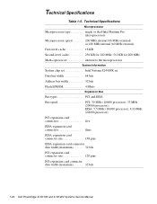
Technical Specifications (continued) System Clocks System clock 60 or 66 MHz (matches external processor bus speed) Diskette/communications ports 24 MHz from the system clock Memory Architecture ... connectors; six 1- one 34-pin connector Fan three 3-pin connectors System Overview 1-25 to 1.6-inch-high SCSI hard-disk drives, hot-pluggable with an optional PowerEdge Expandable RAID Controller host adapter card System Board Connectors Externally accessible: Serial (DTE two 9-pin connectors; 16550-compatible (UART) Server Management (serial one 15-hole...
Technical Specifications (continued) System Clocks System clock 60 or 66 MHz (matches external processor bus speed) Diskette/communications ports 24 MHz from the system clock Memory Architecture ... connectors; six 1- one 34-pin connector Fan three 3-pin connectors System Overview 1-25 to 1.6-inch-high SCSI hard-disk drives, hot-pluggable with an optional PowerEdge Expandable RAID Controller host adapter card System Board Connectors Externally accessible: Serial (DTE two 9-pin connectors; 16550-compatible (UART) Server Management (serial one 15-hole...
Service Manual
Page 28
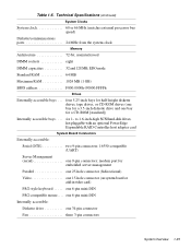
one 16-pin connector (server management) to CD-ROM SMB BACKPLANE. . . . . Technical Specifications (continued) System Board Connectors (continued) POWER1 one 18-pin connector: standby power, I2 C, PWRGOOD, and miscellaneous power POWER2 one 20-pin connector: +3.3 VDC, +5 VDC, or... +12 VDC POWER3 one 14-pin connectors Video Video type embedded PCI (see User's Guide for specifications) Video memory 1 MB Key Combinations one 68-pin connector, ultra-wide (fast), to SCSI backplane SCSI2 CD-ROM one 50-pin connector, ultra-narrow, to...
one 16-pin connector (server management) to CD-ROM SMB BACKPLANE. . . . . Technical Specifications (continued) System Board Connectors (continued) POWER1 one 18-pin connector: standby power, I2 C, PWRGOOD, and miscellaneous power POWER2 one 20-pin connector: +3.3 VDC, +5 VDC, or... +12 VDC POWER3 one 14-pin connectors Video Video type embedded PCI (see User's Guide for specifications) Video memory 1 MB Key Combinations one 68-pin connector, ultra-wide (fast), to SCSI backplane SCSI2 CD-ROM one 50-pin connector, ultra-narrow, to...
Service Manual
Page 29
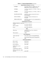
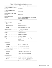
Table 1-5. Technical Specifications (continued) Controls and Indicators (continued) SCSI hard-disk drive activity indicator green LED SCSI hard-disk drive fault indicator yellow LED Power-supply 5-VDC online ...
Table 1-5. Technical Specifications (continued) Controls and Indicators (continued) SCSI hard-disk drive activity indicator green LED SCSI hard-disk drive fault indicator yellow LED Power-supply 5-VDC online ...
Service Manual
Page 30
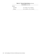
Technical Specifications (continued) Environmental (continued) Altitude: Operating 16 to 3048 m (-50 to 10,000 ft) Storage 16 to 10,600 m (-50 to 35,000 ft) z 1-28 Dell PowerEdge 4100/180 and 4100/200 Systems Service Manual Table 1-5.
Technical Specifications (continued) Environmental (continued) Altitude: Operating 16 to 3048 m (-50 to 10,000 ft) Storage 16 to 10,600 m (-50 to 35,000 ft) z 1-28 Dell PowerEdge 4100/180 and 4100/200 Systems Service Manual Table 1-5.
Service Manual
Page 36
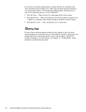
...Dell PowerEdge 4100/180 and 4100/200 Systems Service Manual Runs all test groups to quickly locate a failure or to indicate where further testing is needed to the proper troubleshooting steps for determining the source of the problem, call Dell for a thorough check of the problem or leads to isolate a failure • Run Specific...Run System Diagnostics icon by pressing . For instructions, see Chapter 11, "Getting Help," in main memory, and the Dell Server Assistant loads, select the Run System Utilities icon. The Diagnostics Menu appears, allowing you to choose the following options...
...Dell PowerEdge 4100/180 and 4100/200 Systems Service Manual Runs all test groups to quickly locate a failure or to indicate where further testing is needed to the proper troubleshooting steps for determining the source of the problem, call Dell for a thorough check of the problem or leads to isolate a failure • Run Specific...Run System Diagnostics icon by pressing . For instructions, see Chapter 11, "Getting Help," in main memory, and the Dell Server Assistant loads, select the Run System Utilities icon. The Diagnostics Menu appears, allowing you to choose the following options...
Service Manual
Page 67
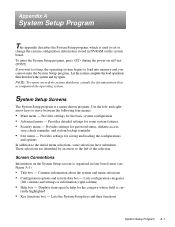
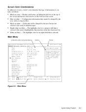
..., consult the documentation that accompanied the operating system. and rightarrow keys to load into memory and you cannot enter the System Setup program. Displays item-specific help for the category whose field is a menu-driven program. rently highlighted • Key functions box - Provides settings for the basic system configuration • Advanced...
..., consult the documentation that accompanied the operating system. and rightarrow keys to load into memory and you cannot enter the System Setup program. Displays item-specific help for the category whose field is a menu-driven program. rently highlighted • Key functions box - Provides settings for the basic system configuration • Advanced...
Service Manual
Page 69
... box title box Dell System PowerEdge 4100/200 Setup Main Advanced Security Exit Time: [5:01:96] Date: [May 04, 1996] Diskette Drive A: [1.44 MB, 3.5 inch] Diskette Drive B: [Not Installed] Fast Video BIOS: [On and Cached] Memory Cache: [Enable] Boot Sequence: [A: then C:] Num Lock: [On] Speaker: [On] BIOS Version AXX Item Specific Help Resets the...
... box title box Dell System PowerEdge 4100/200 Setup Main Advanced Security Exit Time: [5:01:96] Date: [May 04, 1996] Diskette Drive A: [1.44 MB, 3.5 inch] Diskette Drive B: [Not Installed] Fast Video BIOS: [On and Cached] Memory Cache: [Enable] Boot Sequence: [A: then C:] Num Lock: [On] Speaker: [On] BIOS Version AXX Item Specific Help Resets the...
Service Manual
Page 71
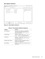
Boot Options Submenu Dell System PowerEdge 4100/200 Setup Main Advanced Security Exit Boot Options Boot Sequence: [A: then C:] Setup Prompt: [Enabled] POST Errors: [Enabled] Diskette Drive Check: [Enabled] Reset Button: [Enabled] BIOS Version AXX Item Specific Help Determines the order of diskette drive during boot Reset Button Enables or disables the reset button on Setup...
Boot Options Submenu Dell System PowerEdge 4100/200 Setup Main Advanced Security Exit Boot Options Boot Sequence: [A: then C:] Setup Prompt: [Enabled] POST Errors: [Enabled] Diskette Drive Check: [Enabled] Reset Button: [Enabled] BIOS Version AXX Item Specific Help Determines the order of diskette drive during boot Reset Button Enables or disables the reset button on Setup...
Service Manual
Page 72
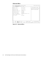
...-Board SCSI B: PCI Scan Sequence Use MP Specification PS/2 Mouse [3F8, IRQ 4] [2F8, IRQ 3] [378, IRQ 7] [Output only] [Enabled] [Enabled] {Enabled} [Embedded devices first] {1.4} [Enabled] BIOS Version AXX Item Specific Help Configures the system's built-in serial port. Advanced Menu F9 Setup Defaults F10 Previous Values A-6 Dell PowerEdge 4100/180 and 4100/200 Systems Service Manual
...-Board SCSI B: PCI Scan Sequence Use MP Specification PS/2 Mouse [3F8, IRQ 4] [2F8, IRQ 3] [378, IRQ 7] [Output only] [Enabled] [Enabled] {Enabled} [Embedded devices first] {1.4} [Enabled] BIOS Version AXX Item Specific Help Configures the system's built-in serial port. Advanced Menu F9 Setup Defaults F10 Previous Values A-6 Dell PowerEdge 4100/180 and 4100/200 Systems Service Manual
Service Manual
Page 73
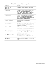
... SCSI A Enables or disables the built-in SCSI 7860 Ultra/Narrow controller and determines if it is Embedded devices first). System Setup Program A-7 Use MP Specification Determines the microprocessorspecification revision level: either 1.1 or 1.4 (default). Advanced Menu Categories Category Function Serial Port 1 or Serial Port 2 Configures system's built-in mouse controller. Diskette...
... SCSI A Enables or disables the built-in SCSI 7860 Ultra/Narrow controller and determines if it is Embedded devices first). System Setup Program A-7 Use MP Specification Determines the microprocessorspecification revision level: either 1.1 or 1.4 (default). Advanced Menu Categories Category Function Serial Port 1 or Serial Port 2 Configures system's built-in mouse controller. Diskette...
Service Manual
Page 74
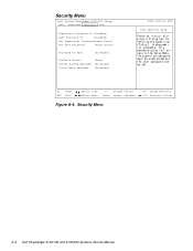
Security Menu A-8 Dell PowerEdge 4100/180 and 4100/200 Systems Service Manual Security Menu Dell System PowerEdge 4100/200 Setup Main Advanced Security Exit Supervisor Password Is Disabled User Password Is Disabled Set Supervisor Password[Press Enter] Set User Password [Press Enter] Password on Boot [Disabled] Diskette Access [User] System Backup Reminder [Disabled] Virus Check Reminder [Disabled] BIOS Version AXX Item Specific Help F1 Help ESC Exit Select Item Select Menu -/+ Change Values Enter Select Sub-Menu F9 Setup Defaults F10 Previous Values Figure A-4.
Security Menu A-8 Dell PowerEdge 4100/180 and 4100/200 Systems Service Manual Security Menu Dell System PowerEdge 4100/200 Setup Main Advanced Security Exit Supervisor Password Is Disabled User Password Is Disabled Set Supervisor Password[Press Enter] Set User Password [Press Enter] Password on Boot [Disabled] Diskette Access [User] System Backup Reminder [Disabled] Virus Check Reminder [Disabled] BIOS Version AXX Item Specific Help F1 Help ESC Exit Select Item Select Menu -/+ Change Values Enter Select Sub-Menu F9 Setup Defaults F10 Previous Values Figure A-4.
Service Manual
Page 76
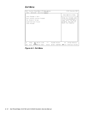
Exit Menu Dell System PowerEdge 4100/200 Setup Main Advanced Security Exit Save Changes & Exit Exit Without Saving Changes Get Default Values Load Previous Values Save Changes BIOS Version AXX Item Specific Help Saves all changes made in the Setup program to CMOS, exits the Setup program, and then reboots the computer. F1 Help ESC Exit Select Item Select Menu -/+ Change Values Enter Select Sub-Menu Figure A-5. Exit Menu F9 Setup Defaults F10 Previous Values A-10 Dell PowerEdge 4100/180 and 4100/200 Systems Service Manual
Exit Menu Dell System PowerEdge 4100/200 Setup Main Advanced Security Exit Save Changes & Exit Exit Without Saving Changes Get Default Values Load Previous Values Save Changes BIOS Version AXX Item Specific Help Saves all changes made in the Setup program to CMOS, exits the Setup program, and then reboots the computer. F1 Help ESC Exit Select Item Select Menu -/+ Change Values Enter Select Sub-Menu Figure A-5. Exit Menu F9 Setup Defaults F10 Previous Values A-10 Dell PowerEdge 4100/180 and 4100/200 Systems Service Manual

Service Manual
Page 79
...-slot opening, 4-18 carrier, hard-disk drive removal, 4-9 CD-ROM drive illustrated, 4-5 removal, 4-7 computer back/right side internal view, 1-6 front/left internal view, 1-5 orientation, 1-3 technical specifications, 1-24 configuration guidelines SCSI drives, 1-9 configuration jumpers location on system board, 4-17 connectors location on system board, 4-17 control panel connector, 4-17 illustrated, 1-5 removal, 4-15...
...-slot opening, 4-18 carrier, hard-disk drive removal, 4-9 CD-ROM drive illustrated, 4-5 removal, 4-7 computer back/right side internal view, 1-6 front/left internal view, 1-5 orientation, 1-3 technical specifications, 1-24 configuration guidelines SCSI drives, 1-9 configuration jumpers location on system board, 4-17 connectors location on system board, 4-17 control panel connector, 4-17 illustrated, 1-5 removal, 4-15...
Service Manual
Page 82
... server-management serial port connector location on I/O panel, 1-7 location on system board, 4-17 SMB BACKPLANE connector, 4-17 sockets battery, 4-23 DIMM, 4-17, 4-19 specifications, technical, 1-24 subsystems advanced expansion, 1-8 main memory, 1-21 system board components, 4-17 illustrated, 1-20 jumpers, 1-21 location, 1-5 removing and replacing, 4-24 ... contact, initial, 2-1 V video connector location on I/O panel, 1-7 location on system board, 4-17 video controller, integrated, 1-9 visual inspection external, 2-2 internal, 2-4 4 Dell PowerEdge 4100/180 and 4100/200 Systems Service Manual
... server-management serial port connector location on I/O panel, 1-7 location on system board, 4-17 SMB BACKPLANE connector, 4-17 sockets battery, 4-23 DIMM, 4-17, 4-19 specifications, technical, 1-24 subsystems advanced expansion, 1-8 main memory, 1-21 system board components, 4-17 illustrated, 1-20 jumpers, 1-21 location, 1-5 removing and replacing, 4-24 ... contact, initial, 2-1 V video connector location on I/O panel, 1-7 location on system board, 4-17 video controller, integrated, 1-9 visual inspection external, 2-2 internal, 2-4 4 Dell PowerEdge 4100/180 and 4100/200 Systems Service Manual
