Service Manual
Page 3
... memory. These buses are freestanding or can be rackmounted to integrate your servers. The Pentium Pro microprocessor contains a built-in a traditional personal computer, Dell PowerEdge 4100 systems include the following new and/or advanced features: • 256 KB (PowerEdge 4100/180 systems) or 512 KB (PowerEdge 4100/200 systems) of cache memory internal to six hard-disk drives...
... memory. These buses are freestanding or can be rackmounted to integrate your servers. The Pentium Pro microprocessor contains a built-in a traditional personal computer, Dell PowerEdge 4100 systems include the following new and/or advanced features: • 256 KB (PowerEdge 4100/180 systems) or 512 KB (PowerEdge 4100/200 systems) of cache memory internal to six hard-disk drives...

Service Manual
Page 4
...interface • Integrated ultra-wide and ultra-narrow SCSI controllers • Integrated server management circuitry that monitors critical system volt- For information about installing the PowerEdge 4100 systems in this chapter. (For more information about the Quick Test option in... list of system features, see "Technical Specifications" found later in a rack, see the "Dell PowerEdge 4100 and 6100 Systems Rack Kit Installation Guide" (P/N 40722). 1-2 Dell PowerEdge 4100/180 and 4100/200 Systems Service Manual • Error correction code (ECC) feature built into the memory controller...
...interface • Integrated ultra-wide and ultra-narrow SCSI controllers • Integrated server management circuitry that monitors critical system volt- For information about installing the PowerEdge 4100 systems in this chapter. (For more information about the Quick Test option in... list of system features, see "Technical Specifications" found later in a rack, see the "Dell PowerEdge 4100 and 6100 Systems Rack Kit Installation Guide" (P/N 40722). 1-2 Dell PowerEdge 4100/180 and 4100/200 Systems Service Manual • Error correction code (ECC) feature built into the memory controller...
Service Manual
Page 8
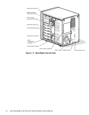
Back/Right Internal View SCSI connector port 1-6 Dell PowerEdge 4100/180 and 4100/200 Systems Service Manual external drive bays (4) diskette interface cable (ultra-narrow) SCSI interface connector (ultra-wide) internal drive bays (6) SCSI backplane board SCSI power connector server management connector control panel connector power supply (optional) power supply SMB connector Figure 1-4.
Back/Right Internal View SCSI connector port 1-6 Dell PowerEdge 4100/180 and 4100/200 Systems Service Manual external drive bays (4) diskette interface cable (ultra-narrow) SCSI interface connector (ultra-wide) internal drive bays (6) SCSI backplane board SCSI power connector server management connector control panel connector power supply (optional) power supply SMB connector Figure 1-4.
Service Manual
Page 10
... of both capacities can be obtained from such an arrangement. Chapter 5, "Using the EISA Configuration Utility," in the Dell PowerEdge 4100/180 and 4100/200 Systems User's Guide describes the EISA Configuration Utility and provides instructions for information on removing and replacing DIMMs. Advanced...eight 168-pin DIMM sockets. and 128-MB buffered, EDO dual in conjunction with the Intel LANDesk® Server Management suite. 1-8 Dell PowerEdge 4100/180 and 4100/200 Systems Service Manual After all legacy cards have a minimum of 64 MB of traditional EISA expansion cards,...
... of both capacities can be obtained from such an arrangement. Chapter 5, "Using the EISA Configuration Utility," in the Dell PowerEdge 4100/180 and 4100/200 Systems User's Guide describes the EISA Configuration Utility and provides instructions for information on removing and replacing DIMMs. Advanced...eight 168-pin DIMM sockets. and 128-MB buffered, EDO dual in conjunction with the Intel LANDesk® Server Management suite. 1-8 Dell PowerEdge 4100/180 and 4100/200 Systems Service Manual After all legacy cards have a minimum of 64 MB of traditional EISA expansion cards,...

Service Manual
Page 17
DC Power Distribution (Nonredundant System) Figures 1-11 provides information about DC power distribution for the nonredundant PowerEdge 4100 system. Power Distribution (Nonredundant System) speaker System Overview 1-15 system board keyboard controller power management logic PWRGOOD PSON# +5 VFP +5 VDC -5 ...+12 VDC +5 VDC +3.3 VDC P3 +12 VDC +5 VDC +3.3 VDC DDBP +12 VDC +5 VDC FD1-4 +12 VDC +5 VDC power connector panel NOTE: A server management cable (16-pin) carries the +5 VFP from SCSI backplane 3 X 6 LEDs reset on/off power-on LED Figure 1-11. The control panel cable (30...
DC Power Distribution (Nonredundant System) Figures 1-11 provides information about DC power distribution for the nonredundant PowerEdge 4100 system. Power Distribution (Nonredundant System) speaker System Overview 1-15 system board keyboard controller power management logic PWRGOOD PSON# +5 VFP +5 VDC -5 ...+12 VDC +5 VDC +3.3 VDC P3 +12 VDC +5 VDC +3.3 VDC DDBP +12 VDC +5 VDC FD1-4 +12 VDC +5 VDC power connector panel NOTE: A server management cable (16-pin) carries the +5 VFP from SCSI backplane 3 X 6 LEDs reset on/off power-on LED Figure 1-11. The control panel cable (30...
Service Manual
Page 21
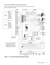
... NOTE: A server management cable (16-pin) carries the +5 VFP from the backplane to the SCSI backplane. The control panel cable (30-pin) carries the +5 VFP from the system board to the control panel. DC Power Distribution (Redundant System) Figures 1-17 provides information about DC power distribution for the redundant PowerEdge 4100 system. SCSI...
... NOTE: A server management cable (16-pin) carries the +5 VFP from the backplane to the SCSI backplane. The control panel cable (30-pin) carries the +5 VFP from the system board to the control panel. DC Power Distribution (Redundant System) Figures 1-17 provides information about DC power distribution for the redundant PowerEdge 4100 system. SCSI...
Service Manual
Page 22
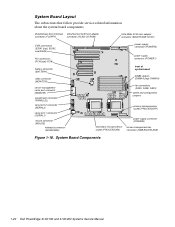
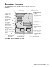
...EISA connectors (EISA1 [top], EISA2, and EISA3) PCI connectors (PCI4 [top]-PCI8) battery connector (BATTERY) video connector (MONITOR) server-management serial port connector (REMOTE) parallel port connector (PARALLEL) serial port 2 connector (SERIAL2) serial port 1 connector (SERIAL1) ... secondary microprocessor server-management bus socket (PROCESSOR2) connector (SMB BACKPLANE) Figure 1-18. System Board Layout The subsections that follow provide service-related information about the system board components. System Board Components 1-20 Dell PowerEdge 4100/180 and 4100/200 Systems Service...
...EISA connectors (EISA1 [top], EISA2, and EISA3) PCI connectors (PCI4 [top]-PCI8) battery connector (BATTERY) video connector (MONITOR) server-management serial port connector (REMOTE) parallel port connector (PARALLEL) serial port 2 connector (SERIAL2) serial port 1 connector (SERIAL1) ... secondary microprocessor server-management bus socket (PROCESSOR2) connector (SMB BACKPLANE) Figure 1-18. System Board Layout The subsections that follow provide service-related information about the system board components. System Board Components 1-20 Dell PowerEdge 4100/180 and 4100/200 Systems Service...
Service Manual
Page 27
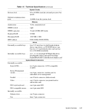
six 1- modem port for embedded server management Parallel one 25-hole connector (bidirectional) Video one 34-pin connector Fan three 3-pin connectors System Overview 1-25 one 6-pin mini-DIN Internally.../2-compatible mouse. . . . to 1.6-inch-high SCSI hard-disk drives, hot-pluggable with an optional PowerEdge Expandable RAID Controller host adapter card System Board Connectors Externally accessible: Serial (DTE two 9-pin connectors; 16550-compatible (UART) Server Management (serial one 9-pin connectors; Table 1-5. Technical Specifications (continued) System Clocks System clock 60 or ...
six 1- modem port for embedded server management Parallel one 25-hole connector (bidirectional) Video one 34-pin connector Fan three 3-pin connectors System Overview 1-25 one 6-pin mini-DIN Internally.../2-compatible mouse. . . . to 1.6-inch-high SCSI hard-disk drives, hot-pluggable with an optional PowerEdge Expandable RAID Controller host adapter card System Board Connectors Externally accessible: Serial (DTE two 9-pin connectors; 16550-compatible (UART) Server Management (serial one 9-pin connectors; Table 1-5. Technical Specifications (continued) System Clocks System clock 60 or ...
Service Manual
Page 28
... 18-pin connector: standby power, I2 C, PWRGOOD, and miscellaneous power POWER2 one 20-pin connector: +3.3 VDC, +5 VDC, or +12 VDC POWER3 one 16-pin connector (server management) to CD-ROM SMB BACKPLANE. . . . . Table 1-5.
... 18-pin connector: standby power, I2 C, PWRGOOD, and miscellaneous power POWER2 one 20-pin connector: +3.3 VDC, +5 VDC, or +12 VDC POWER3 one 16-pin connector (server management) to CD-ROM SMB BACKPLANE. . . . . Table 1-5.

Service Manual
Page 33
... 30 seconds), the Num Lock indicator should light up and remain on. This single beep is normal and is operational, troubleshoot the memory. 4. Insert the Dell Server Assistant CD into the CD-ROM drive. NOTE: The center fan is normally off , turn on all peripherals and the computer. Proceed to or from...
... 30 seconds), the Num Lock indicator should light up and remain on. This single beep is normal and is operational, troubleshoot the memory. 4. Insert the Dell Server Assistant CD into the CD-ROM drive. NOTE: The center fan is normally off , turn on all peripherals and the computer. Proceed to or from...
Service Manual
Page 34
...all the AC power cables from its connector, and carefully push it . Then reinstall the cardmounting bracket's retaining screw. 2-4 Dell PowerEdge 4100/180 and 4100/200 Systems Service Manual Remove the left computer cover. 3. Yes. To maintain proper air flow and prevent the system from its.... Be sure the chip has had sufficient time to locate components in their sockets or connectors. Observe the monitor screen for the Dell Server Assistant Menu. To perform the internal visual inspection, follow these steps: 1. To reseat a DIMM, remove it as the micro-...
...all the AC power cables from its connector, and carefully push it . Then reinstall the cardmounting bracket's retaining screw. 2-4 Dell PowerEdge 4100/180 and 4100/200 Systems Service Manual Remove the left computer cover. 3. Yes. To maintain proper air flow and prevent the system from its.... Be sure the chip has had sufficient time to locate components in their sockets or connectors. Observe the monitor screen for the Dell Server Assistant Menu. To perform the internal visual inspection, follow these steps: 1. To reseat a DIMM, remove it as the micro-...

Service Manual
Page 35
...available. No. Eliminating Resource Conflicts Devices within the computer may be installed at all. If you which must be resolved? Before the Dell Server Assistant loads, a program tests the portion of the computer system. Basic Troubleshooting 2-5 Reinstall the computer cover. 7. To start the ... appear to their power sources, and turn them on the screen. Running the System Diagnostics The system diagnostics (included on the Dell Server Assistant CD) contains tests that the same resource is assigned to operate at a different time, it is detected, a message telling...
...available. No. Eliminating Resource Conflicts Devices within the computer may be installed at all. If you which must be resolved? Before the Dell Server Assistant loads, a program tests the portion of the computer system. Basic Troubleshooting 2-5 Reinstall the computer cover. 7. To start the ... appear to their power sources, and turn them on the screen. Running the System Diagnostics The system diagnostics (included on the Dell Server Assistant CD) contains tests that the same resource is assigned to operate at a different time, it is detected, a message telling...
Service Manual
Page 36
If no errors are found in the Installation and Troubleshooting Guide. 2-6 Dell PowerEdge 4100/180 and 4100/200 Systems Service Manual Tests a particular area or subsystem Getting Help If none of the troubleshooting procedures in this chapter or the tests in the ... determining the source of the system • Run Quick Tests - For instructions, see Chapter 11, "Getting Help," in main memory, and the Dell Server Assistant loads, select the Run System Utilities icon. Then select the Run System Diagnostics icon by pressing . The Diagnostics Menu appears, allowing you to choose ...
If no errors are found in the Installation and Troubleshooting Guide. 2-6 Dell PowerEdge 4100/180 and 4100/200 Systems Service Manual Tests a particular area or subsystem Getting Help If none of the troubleshooting procedures in this chapter or the tests in the ... determining the source of the system • Run Quick Tests - For instructions, see Chapter 11, "Getting Help," in main memory, and the Dell Server Assistant loads, select the Run System Utilities icon. Then select the Run System Diagnostics icon by pressing . The Diagnostics Menu appears, allowing you to choose ...

Service Manual
Page 41
...greater. Replace microprocessor with correct sA1 stepping or greater. Power supply paralleling board firmware download failed System backplane firmware download failed Server-management bus cable connection to system board (labeled "SMB BACKPLANE") and SCSI backplane (labeled "SMB"). System halted. Replace ...Cache memory sizes of CPU is neither 180 MHz or 200 MHz. System halted. Embedded server management firmware download failed Embedded server management memory temporarily corrupted. Turn off and then restart the system. Turn off and then restart system.
...greater. Replace microprocessor with correct sA1 stepping or greater. Power supply paralleling board firmware download failed System backplane firmware download failed Server-management bus cable connection to system board (labeled "SMB BACKPLANE") and SCSI backplane (labeled "SMB"). System halted. Replace ...Cache memory sizes of CPU is neither 180 MHz or 200 MHz. System halted. Embedded server management firmware download failed Embedded server management memory temporarily corrupted. Turn off and then restart the system. Turn off and then restart system.

Service Manual
Page 58
... normally turned off by releasing the two fan retention tabs inside the carrier. 4-16 Dell PowerEdge 4100/180 and 4100/200 Systems Service Manual Remove the left computer cover. 2. Disconnect the cooling fan's power cable from the fan carrier by server management; The middle fan is turned on the fan carrier, and remove the fan...
... normally turned off by releasing the two fan retention tabs inside the carrier. 4-16 Dell PowerEdge 4100/180 and 4100/200 Systems Service Manual Remove the left computer cover. 2. Disconnect the cooling fan's power cable from the fan carrier by server management; The middle fan is turned on the fan carrier, and remove the fan...
Service Manual
Page 59
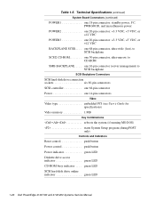
...], EISA2, and EISA3) PCI connectors (PCI4 [top]-PCI8) Ultra/Narrow SCSI host adapter connector (SCSI2 CD-ROM) battery connector (BATTERY) video connector (MONITOR) server-management serial port connector (REMOTE) parallel port connector (PARALLEL) serial port 2 connector (SERIAL2) serial port 1 connector (SERIAL1) mouse connector (MOUSE) keyboard connector... [top]-DIMM H) fan connectors (FAN1, FAN2, FAN3) speed and configuration jumpers primary microprocessor socket (PROCESSOR1) power supply connector (POWER3) server-management bus connector (SMB BACKPLANE) Removing and Replacing Parts 4-17
...], EISA2, and EISA3) PCI connectors (PCI4 [top]-PCI8) Ultra/Narrow SCSI host adapter connector (SCSI2 CD-ROM) battery connector (BATTERY) video connector (MONITOR) server-management serial port connector (REMOTE) parallel port connector (PARALLEL) serial port 2 connector (SERIAL2) serial port 1 connector (SERIAL1) mouse connector (MOUSE) keyboard connector... [top]-DIMM H) fan connectors (FAN1, FAN2, FAN3) speed and configuration jumpers primary microprocessor socket (PROCESSOR1) power supply connector (POWER3) server-management bus connector (SMB BACKPLANE) Removing and Replacing Parts 4-17

Service Manual
Page 80
..., 4-5 help, getting, 2-6 I indicator card removal, 4-11 initial procedures, 2-1 initialization error messages, 3-3 integrated features SCSI controllers, 1-9 server management, 1-8 video controller, 1-9 interrupt assignments list of, 1-22 ISA expansion cards, 4-18 J jumpers list of, 1-22 K KEYBOARD connector, 4-17 keyboard connector location on I/O panel, 1-7 location on system board, 4-17 2 Dell PowerEdge 4100/180 and 4100/200 Systems Service Manual
..., 4-5 help, getting, 2-6 I indicator card removal, 4-11 initial procedures, 2-1 initialization error messages, 3-3 integrated features SCSI controllers, 1-9 server management, 1-8 video controller, 1-9 interrupt assignments list of, 1-22 ISA expansion cards, 4-18 J jumpers list of, 1-22 K KEYBOARD connector, 4-17 keyboard connector location on I/O panel, 1-7 location on system board, 4-17 2 Dell PowerEdge 4100/180 and 4100/200 Systems Service Manual
Service Manual
Page 82
serial port connectors location on I/O panel, 1-7 location on system board, 4-17 server-management bus connector, 4-17 server-management serial port connector location on I/O panel, 1-7 location on system board, 4-17 SMB BACKPLANE connector, 4-17 sockets battery, 4-23 DIMM, 4-17, 4-19 specifications, technical, 1-24 ... SCSI host adapter connector, 4- 17 user contact, initial, 2-1 V video connector location on I/O panel, 1-7 location on system board, 4-17 video controller, integrated, 1-9 visual inspection external, 2-2 internal, 2-4 4 Dell PowerEdge 4100/180 and 4100/200 Systems Service Manual
serial port connectors location on I/O panel, 1-7 location on system board, 4-17 server-management bus connector, 4-17 server-management serial port connector location on I/O panel, 1-7 location on system board, 4-17 SMB BACKPLANE connector, 4-17 sockets battery, 4-23 DIMM, 4-17, 4-19 specifications, technical, 1-24 ... SCSI host adapter connector, 4- 17 user contact, initial, 2-1 V video connector location on I/O panel, 1-7 location on system board, 4-17 video controller, integrated, 1-9 visual inspection external, 2-2 internal, 2-4 4 Dell PowerEdge 4100/180 and 4100/200 Systems Service Manual


