Service Manual
Page 3
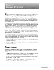
... allow you to six hard-disk drives • Optional, redundant hot-pluggable power supplies System Overview 1-1 The microprocessors for information about Dellsupported microprocessor upgrades. PowerEdge 4100 systems incorporate the high-performance peripheral component interconnect (PCI) local bus as well as follows: • Dell PowerEdge 4100/180 system - 180 MHz derived from a system clock frequency of 60 MHz...
... allow you to six hard-disk drives • Optional, redundant hot-pluggable power supplies System Overview 1-1 The microprocessors for information about Dellsupported microprocessor upgrades. PowerEdge 4100 systems incorporate the high-performance peripheral component interconnect (PCI) local bus as well as follows: • Dell PowerEdge 4100/180 system - 180 MHz derived from a system clock frequency of 60 MHz...
Service Manual
Page 8
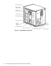
external drive bays (4) diskette interface cable (ultra-narrow) SCSI interface connector (ultra-wide) internal drive bays (6) SCSI backplane board SCSI power connector server management connector control panel connector power supply (optional) power supply SMB connector Figure 1-4. Back/Right Internal View SCSI connector port 1-6 Dell PowerEdge 4100/180 and 4100/200 Systems Service Manual
external drive bays (4) diskette interface cable (ultra-narrow) SCSI interface connector (ultra-wide) internal drive bays (6) SCSI backplane board SCSI power connector server management connector control panel connector power supply (optional) power supply SMB connector Figure 1-4. Back/Right Internal View SCSI connector port 1-6 Dell PowerEdge 4100/180 and 4100/200 Systems Service Manual
Service Manual
Page 13
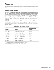
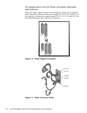
... 1-1. Therefore, when you measure these voltages, the DC power connectors must be connected to their corresponding power input connectors on the power supply is lit (except during power-up), it indicates that the power supply has failed (see Figure 1-5). DC Voltage Ranges Voltage Range...is installed, the power supplies are hot-pluggable. System Power Supply The 500-W system power supply can operate from an AC power source of 90 to +5.36 VDC 1 Maximum continuous DC output power shall not exceed 500 W. 2 VFP (volts flea power) - When the power-supply paralleling board is ...
... 1-1. Therefore, when you measure these voltages, the DC power connectors must be connected to their corresponding power input connectors on the power supply is lit (except during power-up), it indicates that the power supply has failed (see Figure 1-5). DC Voltage Ranges Voltage Range...is installed, the power supplies are hot-pluggable. System Power Supply The 500-W system power supply can operate from an AC power source of 90 to +5.36 VDC 1 Maximum continuous DC output power shall not exceed 500 W. 2 VFP (volts flea power) - When the power-supply paralleling board is ...
Service Manual
Page 14
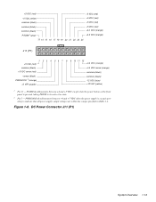
Power Supply Connectors J12 (P2) J11 (P1) J15 (P5) J14 (P4) J13 (P3) Figure 1-7. Pin Assignments for the DC Power Connectors (Nonredundant Systems) The power-supply output voltages for nonredundant systems can be measured at the connectors on the back of connectors. Power Connector Panel 1-12 Dell PowerEdge 4100/180 and 4100/200 Systems Service Manual The following illustrations show both sets of the power supply (P1, P2, P3, P4, and P5) or at the connectors on the power connector panel (J11, J12, J13, J14, and J15). P2 P1 P5 P4 P3 Figure 1-6.
Power Supply Connectors J12 (P2) J11 (P1) J15 (P5) J14 (P4) J13 (P3) Figure 1-7. Pin Assignments for the DC Power Connectors (Nonredundant Systems) The power-supply output voltages for nonredundant systems can be measured at the connectors on the back of connectors. Power Connector Panel 1-12 Dell PowerEdge 4100/180 and 4100/200 Systems Service Manual The following illustrations show both sets of the power supply (P1, P2, P3, P4, and P5) or at the connectors on the power connector panel (J11, J12, J13, J14, and J15). P2 P1 P5 P4 P3 Figure 1-6.
Service Manual
Page 15
...yellow) 1 Pin 13 - DC Power Connector J11 (P1) System Overview 1-13 PSON# should measure between +4 and +5 VDC except when the power button on and operating to its active-low state. 2 Pin 5 - PWRGOOD should measure between +4 and +5 VDC when the power supply is on the front panel is ...pressed, taking PSON# to indicate that all power-supply output voltages are within the ranges specified ...
...yellow) 1 Pin 13 - DC Power Connector J11 (P1) System Overview 1-13 PSON# should measure between +4 and +5 VDC except when the power button on and operating to its active-low state. 2 Pin 5 - PWRGOOD should measure between +4 and +5 VDC when the power supply is on the front panel is ...pressed, taking PSON# to indicate that all power-supply output voltages are within the ranges specified ...

Service Manual
Page 17
... 1-15 P1-5 power supply # 1 PSON# +5 VFP +5 VDC -5 VDC +12 VDC -12 VDC +3.3 VDC P1 NRLED PWRGOOD PSON# +5 VFP +5 VDC -5 VDC +12 VDC -12 VDC +3.3 VDC P2 +12 VDC +5 VDC +3.3 VDC P3 +12 VDC +5 VDC +3.3 VDC DDBP +12 VDC +5 VDC FD1-4 +12 VDC +5 VDC power connector panel NOTE:...CD-ROM FLOPPY 654321 control panel +5 VFP from the system board to the control panel. DC Power Distribution (Nonredundant System) Figures 1-11 provides information about DC power distribution for the nonredundant PowerEdge 4100 system. The control panel cable (30-pin) carries the +5 VFP from the backplane to the ...
... 1-15 P1-5 power supply # 1 PSON# +5 VFP +5 VDC -5 VDC +12 VDC -12 VDC +3.3 VDC P1 NRLED PWRGOOD PSON# +5 VFP +5 VDC -5 VDC +12 VDC -12 VDC +3.3 VDC P2 +12 VDC +5 VDC +3.3 VDC P3 +12 VDC +5 VDC +3.3 VDC DDBP +12 VDC +5 VDC FD1-4 +12 VDC +5 VDC power connector panel NOTE:...CD-ROM FLOPPY 654321 control panel +5 VFP from the system board to the control panel. DC Power Distribution (Nonredundant System) Figures 1-11 provides information about DC power distribution for the nonredundant PowerEdge 4100 system. The control panel cable (30-pin) carries the +5 VFP from the backplane to the ...
Service Manual
Page 18
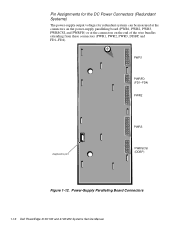
Power-Supply Paralleling Board Connectors 1-16 Dell PowerEdge 4100/180 and 4100/200 Systems Service Manual Pin Assignments for the DC Power Connectors (Redundant Systems) The power-supply output voltages for redundant systems can be measured at the connectors on the power-supply paralleling board (PWR1, PWR2, PWR3, PWRSCSI, and PWRFD) or at the connectors on the end of the wire bundles extending from these connectors (PWR1, PWR2, PWR3, DDBP, and FD1-FD4). PWR1 PWRFD (FD1-FD4) PWR2 diagnostics port PWR3 PWRSCSI (DDBP) Figure 1-12.
Power-Supply Paralleling Board Connectors 1-16 Dell PowerEdge 4100/180 and 4100/200 Systems Service Manual Pin Assignments for the DC Power Connectors (Redundant Systems) The power-supply output voltages for redundant systems can be measured at the connectors on the power-supply paralleling board (PWR1, PWR2, PWR3, PWRSCSI, and PWRFD) or at the connectors on the end of the wire bundles extending from these connectors (PWR1, PWR2, PWR3, DDBP, and FD1-FD4). PWR1 PWRFD (FD1-FD4) PWR2 diagnostics port PWR3 PWRSCSI (DDBP) Figure 1-12.
Service Manual
Page 21
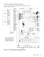
... System) Figures 1-17 provides information about DC power distribution for the redundant PowerEdge 4100 system. SCSI backplane (six drive bays) 654321 CD-ROM FLOPPY control panel +5 VFP from the system board to the control panel. power supply # 1 P1-5 POK PSON# +5 VFP +5 VDC -5 VDC +12 VDC -12 VDC +3.3 VDC P1-5 power supply # 2 PSON# +5 VFP +5 VDC -5 VDC +12 VDC...
... System) Figures 1-17 provides information about DC power distribution for the redundant PowerEdge 4100 system. SCSI backplane (six drive bays) 654321 CD-ROM FLOPPY control panel +5 VFP from the system board to the control panel. power supply # 1 P1-5 POK PSON# +5 VFP +5 VDC -5 VDC +12 VDC -12 VDC +3.3 VDC P1-5 power supply # 2 PSON# +5 VFP +5 VDC -5 VDC +12 VDC...
Service Manual
Page 22
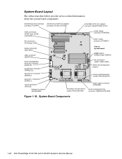
System Board Components 1-20 Dell PowerEdge 4100/180 and 4100/200 Systems Service Manual System Board Layout The subsections that follow provide service-related information about the system board components... connector (REMOTE) parallel port connector (PARALLEL) serial port 2 connector (SERIAL2) serial port 1 connector (SERIAL1) mouse connector (MOUSE) keyboard connector (KEYBOARD) power supply connector (POWER2) power supply connector (POWER1) front of system board DIMM sockets (DIMM A [top]-DIMM H) fan connectors (FAN1, FAN2, FAN3) speed and configuration jumpers primary microprocessor ...
System Board Components 1-20 Dell PowerEdge 4100/180 and 4100/200 Systems Service Manual System Board Layout The subsections that follow provide service-related information about the system board components... connector (REMOTE) parallel port connector (PARALLEL) serial port 2 connector (SERIAL2) serial port 1 connector (SERIAL1) mouse connector (MOUSE) keyboard connector (KEYBOARD) power supply connector (POWER2) power supply connector (POWER1) front of system board DIMM sockets (DIMM A [top]-DIMM H) fan connectors (FAN1, FAN2, FAN3) speed and configuration jumpers primary microprocessor ...
Service Manual
Page 29
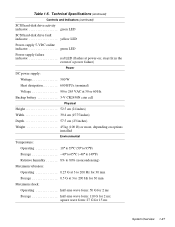
square wave form: 27 G for 2 ms; stays lit in the event of a power failure) Power DC power supply: Wattage 500 W Heat dissipation 600 BTUs (nominal) Voltage 90 to 265 VAC at 50 or 60 Hz Backup battery 3-V CR2450N coin cell Physical Height 52.5 ...) SCSI hard-disk drive activity indicator green LED SCSI hard-disk drive fault indicator yellow LED Power-supply 5-VDC online indicator green LED Power-supply failure indicator red LED (flashes at 3 to 200 Hz for 30 min Storage 0.5 G at power-on options installed Environmental Temperature: Operating 10° to 35°C (50° to 95...
square wave form: 27 G for 2 ms; stays lit in the event of a power failure) Power DC power supply: Wattage 500 W Heat dissipation 600 BTUs (nominal) Voltage 90 to 265 VAC at 50 or 60 Hz Backup battery 3-V CR2450N coin cell Physical Height 52.5 ...) SCSI hard-disk drive activity indicator green LED SCSI hard-disk drive fault indicator yellow LED Power-supply 5-VDC online indicator green LED Power-supply failure indicator red LED (flashes at 3 to 200 Hz for 30 min Storage 0.5 G at power-on options installed Environmental Temperature: Operating 10° to 35°C (50° to 95...

Service Manual
Page 33
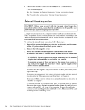
Insert the Dell Server Assistant CD into the CD-ROM drive. Yes. Yes. If...vide status information. Observing the Boot Routine After you have performed an external visual inspection as appropriate. Check the power supply fans. During the boot routine, observe the computer for any of the following a long pause (approximately 30 ... of the keyboard. Press the reset button or to step 3. Do the fans run normally? Troubleshoot the system power supply. 3. Basic Troubleshooting 2-3 No. It may be necessary to reboot the system several times in this procedure require ...
Insert the Dell Server Assistant CD into the CD-ROM drive. Yes. Yes. If...vide status information. Observing the Boot Routine After you have performed an external visual inspection as appropriate. Check the power supply fans. During the boot routine, observe the computer for any of the following a long pause (approximately 30 ... of the keyboard. Press the reset button or to step 3. Do the fans run normally? Troubleshoot the system power supply. 3. Basic Troubleshooting 2-3 No. It may be necessary to reboot the system several times in this procedure require ...
Service Manual
Page 34
... the card by its socket and reinstall it as the micro- 5. Then reinstall the cardmounting bracket's retaining screw. 2-4 Dell PowerEdge 4100/180 and 4100/200 Systems Service Manual Does the menu appear? WARNINGS: The microprocessor can often lead to locate components in their sockets, press... first remove it from its top corners, and carefully pull it . If you touch it out of each power supply bay must have either a power supply or the power closeout panel installed. Yes. To maintain proper air flow and prevent the system from their sockets or connectors. ...
... the card by its socket and reinstall it as the micro- 5. Then reinstall the cardmounting bracket's retaining screw. 2-4 Dell PowerEdge 4100/180 and 4100/200 Systems Service Manual Does the menu appear? WARNINGS: The microprocessor can often lead to locate components in their sockets, press... first remove it from its top corners, and carefully pull it . If you touch it out of each power supply bay must have either a power supply or the power closeout panel installed. Yes. To maintain proper air flow and prevent the system from their sockets or connectors. ...

Service Manual
Page 41
... than sA1 System halted. Replace microprocessor with sA1 stepping or greater. Cache memory sizes of CPU is loose. Check speed jumpers. Check microprocessor speed jumpers. Power supply paralleling board firmware download failed System backplane firmware download failed Server-management bus cable connection to system board (labeled "SMB BACKPLANE") and SCSI backplane (labeled...
... than sA1 System halted. Replace microprocessor with sA1 stepping or greater. Cache memory sizes of CPU is loose. Check speed jumpers. Check microprocessor speed jumpers. Power supply paralleling board firmware download failed System backplane firmware download failed Server-management bus cable connection to system board (labeled "SMB BACKPLANE") and SCSI backplane (labeled...

Service Manual
Page 53
... the board from the ten hooks holding the board to the back of the computer approximately 1 inch. 2. An insulator (similar to the one for the power-supply paralleling board in Figure 4-12) is attached to the computer chassis, and lift the board away from the computer. SCSI Backplane Board hard-disk drive...
... the board from the ten hooks holding the board to the back of the computer approximately 1 inch. 2. An insulator (similar to the one for the power-supply paralleling board in Figure 4-12) is attached to the computer chassis, and lift the board away from the computer. SCSI Backplane Board hard-disk drive...
Service Manual
Page 54
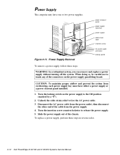
... the power supply out of the cable from the power outlet; Figure 4-11. Power Supply The computer may have either a power supply or a power closeout panel installed. 1. Unhook the cable strain relief to release the power supply. 5. Power Supply Removal power closeout panel power supply (optional) power supply cable strain relief insertion screw AC power cable connector locking switch To remove a power supply, follow these steps in reverse order. 4-12 Dell PowerEdge 4100...
... the power supply out of the cable from the power outlet; Figure 4-11. Power Supply The computer may have either a power supply or a power closeout panel installed. 1. Unhook the cable strain relief to release the power supply. 5. Power Supply Removal power closeout panel power supply (optional) power supply cable strain relief insertion screw AC power cable connector locking switch To remove a power supply, follow these steps in reverse order. 4-12 Dell PowerEdge 4100...

Service Manual
Page 55
... power-supply paralleling board by sliding each power supply toward the back of getting shocked. 1. Disconnect all cables from the computer. Power-Supply Paralleling Board cables thumb screw power supply (2) power-supply paralleling board insulator hook slots (11) power-supply paralleling board Figure 4-12. Power-Supply Paralleling Board Removal (Redundant Systems) To remove a power-supply paralleling board, follow these steps: WARNING: Disconnect both power supplies from their AC power...
... power-supply paralleling board by sliding each power supply toward the back of getting shocked. 1. Disconnect all cables from the computer. Power-Supply Paralleling Board cables thumb screw power supply (2) power-supply paralleling board insulator hook slots (11) power-supply paralleling board Figure 4-12. Power-Supply Paralleling Board Removal (Redundant Systems) To remove a power-supply paralleling board, follow these steps: WARNING: Disconnect both power supplies from their AC power...
Service Manual
Page 56
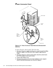
... panel cables (from the computer. 4-14 Dell PowerEdge 4100/180 and 4100/200 Systems Service Manual Unscrew the retainer screw. 4. Power Connector Panel Removal (Nonredundant Systems) To remove the power connector panel, follow these steps: 1. Disengage the panel from the ... backplane board, and so forth). 3. Disconnect the power supply from the power connector panel by sliding the power supply toward the back of the computer approximately 1 inch. 2. Power Connector Panel power supply retainer screw power connector panel cables (5) power connector panel hook slots (4) Figure 4-13.
... panel cables (from the computer. 4-14 Dell PowerEdge 4100/180 and 4100/200 Systems Service Manual Unscrew the retainer screw. 4. Power Connector Panel Removal (Nonredundant Systems) To remove the power connector panel, follow these steps: 1. Disengage the panel from the ... backplane board, and so forth). 3. Disconnect the power supply from the power connector panel by sliding the power supply toward the back of the computer approximately 1 inch. 2. Power Connector Panel power supply retainer screw power connector panel cables (5) power connector panel hook slots (4) Figure 4-13.
Service Manual
Page 59
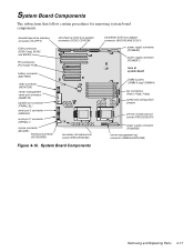
... (KEYBOARD) secondary microprocessor socket (PROCESSOR2) Figure 4-16. System Board Components Ultra/Wide SCSI host adapter connector (BACKPLANE SCSI1) power supply connector (POWER2) power supply connector (POWER1) front of system board DIMM sockets (DIMM A [top]-DIMM H) fan connectors (FAN1, FAN2, FAN3) ...speed and configuration jumpers primary microprocessor socket (PROCESSOR1) power supply connector (POWER3) server-management bus connector (SMB BACKPLANE) Removing and Replacing Parts 4-17 System Board Components The subsections ...
... (KEYBOARD) secondary microprocessor socket (PROCESSOR2) Figure 4-16. System Board Components Ultra/Wide SCSI host adapter connector (BACKPLANE SCSI1) power supply connector (POWER2) power supply connector (POWER1) front of system board DIMM sockets (DIMM A [top]-DIMM H) fan connectors (FAN1, FAN2, FAN3) ...speed and configuration jumpers primary microprocessor socket (PROCESSOR1) power supply connector (POWER3) server-management bus connector (SMB BACKPLANE) Removing and Replacing Parts 4-17 System Board Components The subsections ...
Service Manual
Page 81
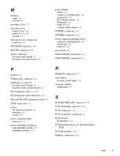
...Plug and Play ISA expansion cards, 1-8 POST beep codes, 3-1 power AC power receptacle, 1-7 indicator, 1-4 switch, 1-4 power connector plate removal, 4-14 power distribution diagram nonredundant system, 1-15 redundant system, 1-19 power supply about, 1-11 connector configuration, 1-12 connectors, 4-17 DC ...voltage ranges, 1-11 illustrated, 1-12 removal, 4-12 voltage output ranges, 1-11 POWER1 connector, 4-17 POWER2 connector, 4-17 power-supply paralleling board connector configuration, 1-16 illustrated, 1-16 removal, 4-13 precautions, 4-2 PROCESSOR1 connector, 4-17 PROCESSOR2 connector, 4-17 R...
...Plug and Play ISA expansion cards, 1-8 POST beep codes, 3-1 power AC power receptacle, 1-7 indicator, 1-4 switch, 1-4 power connector plate removal, 4-14 power distribution diagram nonredundant system, 1-15 redundant system, 1-19 power supply about, 1-11 connector configuration, 1-12 connectors, 4-17 DC ...voltage ranges, 1-11 illustrated, 1-12 removal, 4-12 voltage output ranges, 1-11 POWER1 connector, 4-17 POWER2 connector, 4-17 power-supply paralleling board connector configuration, 1-16 illustrated, 1-16 removal, 4-13 precautions, 4-2 PROCESSOR1 connector, 4-17 PROCESSOR2 connector, 4-17 R...
Service Manual
Page 82
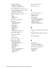
...components, 4-17 illustrated, 1-20 jumpers, 1-21 location, 1-5 removing and replacing, 4-24 system board jumpers, 1-21 system error messages list of, 3-3 system features, 1-1 system power supply, 1-11 System Setup program advanced menu, A-6 boot options submenu, A-5 exit menu, A-10 key functions, A-2 main menu, A-3 menus, A-1 screen color combinations, A-3 screen ..., initial, 2-1 V video connector location on I/O panel, 1-7 location on system board, 4-17 video controller, integrated, 1-9 visual inspection external, 2-2 internal, 2-4 4 Dell PowerEdge 4100/180 and 4100/200 Systems Service Manual
...components, 4-17 illustrated, 1-20 jumpers, 1-21 location, 1-5 removing and replacing, 4-24 system board jumpers, 1-21 system error messages list of, 3-3 system features, 1-1 system power supply, 1-11 System Setup program advanced menu, A-6 boot options submenu, A-5 exit menu, A-10 key functions, A-2 main menu, A-3 menus, A-1 screen color combinations, A-3 screen ..., initial, 2-1 V video connector location on I/O panel, 1-7 location on system board, 4-17 video controller, integrated, 1-9 visual inspection external, 2-2 internal, 2-4 4 Dell PowerEdge 4100/180 and 4100/200 Systems Service Manual


