Service Manual
Page 3
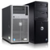
... in a traditional personal computer, Dell PowerEdge 4100 systems include the following new and/or advanced features: • 256 KB (PowerEdge 4100/180 systems) or 512 KB (PowerEdge 4100/200 systems) of cache memory internal to the Pentium Pro module • 64 MB of 72-bit wide, buffered, extended data output (EDO) main memory, upgradable to 1024 MB (1 GB) • Hot-pluggable SCSI backplane supporting up to replace microprocessors faster.
... in a traditional personal computer, Dell PowerEdge 4100 systems include the following new and/or advanced features: • 256 KB (PowerEdge 4100/180 systems) or 512 KB (PowerEdge 4100/200 systems) of cache memory internal to the Pentium Pro module • 64 MB of 72-bit wide, buffered, extended data output (EDO) main memory, upgradable to 1024 MB (1 GB) • Hot-pluggable SCSI backplane supporting up to replace microprocessors faster.

Service Manual
Page 4
... Rack Kit Installation Guide" (P/N 40722). 1-2 Dell PowerEdge 4100/180 and 4100/200 Systems Service Manual ages and temperatures, as well as the operation of the system cooling fans • CD-ROM drive standard in an externally accessible drive bay • Recessed power and reset buttons to the EISA bus, provides a bidirectional parallel port, two serial ports, and the diskette drive interface • Integrated ultra-wide and ultra-narrow SCSI controllers • Integrated server management circuitry that monitors critical system volt- • Error...
... Rack Kit Installation Guide" (P/N 40722). 1-2 Dell PowerEdge 4100/180 and 4100/200 Systems Service Manual ages and temperatures, as well as the operation of the system cooling fans • CD-ROM drive standard in an externally accessible drive bay • Recessed power and reset buttons to the EISA bus, provides a bidirectional parallel port, two serial ports, and the diskette drive interface • Integrated ultra-wide and ultra-narrow SCSI controllers • Integrated server management circuitry that monitors critical system volt- • Error...
Service Manual
Page 10
... any installed Plug and Play ISA expansion cards and PCI expansion cards the next time the system is built into the memory controller on the system board (see Figure 1-18). Integrated Server Management The system board contains integrated server management circuitry that monitors critical system voltages and temperatures, as well as follows: • Populate the DIMM sockets in the Dell PowerEdge 4100/180 and 4100/200 Systems User's Guide describes the EISA Configuration Utility and provides instructions...
... any installed Plug and Play ISA expansion cards and PCI expansion cards the next time the system is built into the memory controller on the system board (see Figure 1-18). Integrated Server Management The system board contains integrated server management circuitry that monitors critical system voltages and temperatures, as well as follows: • Populate the DIMM sockets in the Dell PowerEdge 4100/180 and 4100/200 Systems User's Guide describes the EISA Configuration Utility and provides instructions...
Service Manual
Page 11
... video memory size is connected to provide a high-performance SCSI bus and also controls the six SCSI hard-disk drives in the other two bays. For detailed information about installing externally accessible drives, see Chapter 10, "Installing Drives in the Internal Bays," in SCSI controller. Dell supports the drives it furnishes. The video controller is not upgradable). In the standard Dell PowerEdge 4100 system configuration, the Ultra/Wide SCSI host adapter on the system board. For detailed information about installing SCSI hard-disk drives, see Chapter 9, "Installing Drives...
... video memory size is connected to provide a high-performance SCSI bus and also controls the six SCSI hard-disk drives in the other two bays. For detailed information about installing externally accessible drives, see Chapter 10, "Installing Drives in the Internal Bays," in SCSI controller. Dell supports the drives it furnishes. The video controller is not upgradable). In the standard Dell PowerEdge 4100 system configuration, the Ultra/Wide SCSI host adapter on the system board. For detailed information about installing SCSI hard-disk drives, see Chapter 9, "Installing Drives...
Service Manual
Page 12
... a unique SCSI ID number from Dell, the default SCSI ID numbers are installed, connect the devices as the last device on disabling the device's terminator. 1-10 Dell PowerEdge 4100/180 and 4100/200 Systems Service Manual Therefore, any additional devices attached to the cable. ID settings and termination are handled automatically by ID number. For additional SCSI addressing information, see Chapter 10, "Installing Drives in the Internal Bays," in Ultra/Narrow SCSI host adapter or to 7. When narrow SCSI devices are...
... a unique SCSI ID number from Dell, the default SCSI ID numbers are installed, connect the devices as the last device on disabling the device's terminator. 1-10 Dell PowerEdge 4100/180 and 4100/200 Systems Service Manual Therefore, any additional devices attached to the cable. ID settings and termination are handled automatically by ID number. For additional SCSI addressing information, see Chapter 10, "Installing Drives in the Internal Bays," in Ultra/Narrow SCSI host adapter or to 7. When narrow SCSI devices are...

Service Manual
Page 24
...'s output buffer is enabled) PASSWD Password enable/disable Installed (password feature enabled) CRDBIOS Reserved Not installed (reserved; Interrupt Assignments IRQ Line Used/Available IRQ0 Generated by system timer IRQ1 Generated by super I /O controller to indicate that device connected to parallel port requires service IRQ8 Generated by keyboard controller for each tick of RTC IRQ9 Available for use by expansion card 1-22 Dell PowerEdge 4100/180 and 4100/200 Systems Service Manual do not change ) RSRVD2 Reserved...
...'s output buffer is enabled) PASSWD Password enable/disable Installed (password feature enabled) CRDBIOS Reserved Not installed (reserved; Interrupt Assignments IRQ Line Used/Available IRQ0 Generated by system timer IRQ1 Generated by super I /O controller to indicate that device connected to parallel port requires service IRQ8 Generated by keyboard controller for each tick of RTC IRQ9 Available for use by expansion card 1-22 Dell PowerEdge 4100/180 and 4100/200 Systems Service Manual do not change ) RSRVD2 Reserved...
Service Manual
Page 27
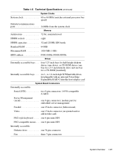
...-high SCSI hard-disk drives, hot-pluggable with an optional PowerEdge Expandable RAID Controller host adapter card System Board Connectors Externally accessible: Serial (DTE two 9-pin connectors; 16550-compatible (UART) Server Management (serial one 15-hole connector (on system board or add-in video card) PS/2-style keyboard . . . . . Table 1-5. Technical Specifications (continued) System Clocks System clock 60 or 66 MHz (matches external processor bus speed) Diskette/communications ports 24 MHz from the system clock Memory Architecture 72-bit, noninterleaved DIMM sockets eight DIMM...
...-high SCSI hard-disk drives, hot-pluggable with an optional PowerEdge Expandable RAID Controller host adapter card System Board Connectors Externally accessible: Serial (DTE two 9-pin connectors; 16550-compatible (UART) Server Management (serial one 15-hole connector (on system board or add-in video card) PS/2-style keyboard . . . . . Table 1-5. Technical Specifications (continued) System Clocks System clock 60 or 66 MHz (matches external processor bus speed) Diskette/communications ports 24 MHz from the system clock Memory Architecture 72-bit, noninterleaved DIMM sockets eight DIMM...
Service Manual
Page 28
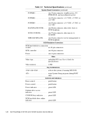
..., ultra-wide (fast), to CD-ROM SMB BACKPLANE. . . . . one 16-pin connector (server management) to SCSI backplane SCSI Backplane Connectors SCSI hard-disk drive connection sockets six 80-pin connectors SCSI controller one 68-pin connector Power one 50-pin connector, ultra-narrow, to SCSI backplane SCSI2 CD-ROM one 14-pin connectors Video Video type embedded PCI (see User's Guide for specifications) Video memory 1 MB Key Combinations Technical Specifications (continued) System Board Connectors (continued) POWER1 one 18-pin connector: standby power, I2 C, PWRGOOD, and miscellaneous...
..., ultra-wide (fast), to CD-ROM SMB BACKPLANE. . . . . one 16-pin connector (server management) to SCSI backplane SCSI Backplane Connectors SCSI hard-disk drive connection sockets six 80-pin connectors SCSI controller one 68-pin connector Power one 50-pin connector, ultra-narrow, to SCSI backplane SCSI2 CD-ROM one 14-pin connectors Video Video type embedded PCI (see User's Guide for specifications) Video memory 1 MB Key Combinations Technical Specifications (continued) System Board Connectors (continued) POWER1 one 18-pin connector: standby power, I2 C, PWRGOOD, and miscellaneous...
Service Manual
Page 31
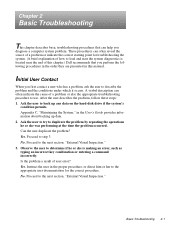
... the appropriate troubleshooting procedure to duplicate the problem by repeating the operations he or she was performing at the time the problem occurred. After the user describes the problem, follow these steps: 1. Ask the user to try to use. Observe the user to load and start the system diagnostics is making an error, such as typing an incorrect key combination or entering a command incorrectly. These...
... the appropriate troubleshooting procedure to duplicate the problem by repeating the operations he or she was performing at the time the problem occurred. After the user describes the problem, follow these steps: 1. Ask the user to try to use. Observe the user to load and start the system diagnostics is making an error, such as typing an incorrect key combination or entering a command incorrectly. These...
Service Manual
Page 32
... a firm connection. 5. Each of the serial and parallel interface cables must be attached to the connector on the device. The captive screws that the video interface cable is firmly attached to the connector on the I/O panel and to one or more keys are identical except for their power sources. 3. Proceed to the next section, "Observing the Boot Routine." 2-2 Dell PowerEdge 4100/180 and 4100/200 Systems Service Manual External Visual...
... a firm connection. 5. Each of the serial and parallel interface cables must be attached to the connector on the device. The captive screws that the video interface cable is firmly attached to the connector on the I/O panel and to one or more keys are identical except for their power sources. 3. Proceed to the next section, "Observing the Boot Routine." 2-2 Dell PowerEdge 4100/180 and 4100/200 Systems Service Manual External Visual...

Service Manual
Page 33
... indicators flash momentarily, and following : • Beep codes: A beep code is a series of the computer is too high. NOTE: The system beeps once during the boot routine, follow these steps. This single beep is normal and is operational, troubleshoot the memory. 4. Basic Troubleshooting 2-3 Insert the Dell Server Assistant CD into the CD-ROM drive. Check the power supply fans. Do these indicators fails to light up during the boot routine, troubleshoot the diskette drive or hard-disk drive...
... indicators flash momentarily, and following : • Beep codes: A beep code is a series of the computer is too high. NOTE: The system beeps once during the boot routine, follow these steps. This single beep is normal and is operational, troubleshoot the memory. 4. Basic Troubleshooting 2-3 Insert the Dell Server Assistant CD into the CD-ROM drive. Check the power supply fans. Do these indicators fails to light up during the boot routine, troubleshoot the diskette drive or hard-disk drive...
Service Manual
Page 34
... an expansion card, use a 1/4-inch nut driver to locate components in this chapter. If you touch it. Reinsert the card in its socket and then reinstall it in Chapter 4. Then reinstall the cardmounting bracket's retaining screw. 2-4 Dell PowerEdge 4100/180 and 4100/200 Systems Service Manual Yes. processor(s) and battery are fully seated in their power sources. 2. To ensure that the user has saved all open files...
... an expansion card, use a 1/4-inch nut driver to locate components in this chapter. If you touch it. Reinsert the card in its socket and then reinstall it in Chapter 4. Then reinstall the cardmounting bracket's retaining screw. 2-4 Dell PowerEdge 4100/180 and 4100/200 Systems Service Manual Yes. processor(s) and battery are fully seated in their power sources. 2. To ensure that the user has saved all open files...
Service Manual
Page 37
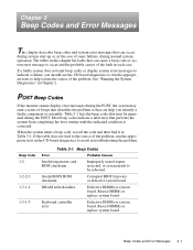
POST Beep Codes If the monitor cannot display error messages during the POST. Invalid BIOS ROM checksum Corrupted BIOS firmware or defective system board. If a faulty system does not emit beep codes or display system error messages to indicate a failure, you identify a faulty component or assembly. See "Running the System Diagnostics" in Table 3-1. If the table does not lead to the source of the fault in troubleshooting the problem. Beep Codes Error Probable Causes Invalid expansion-card ROM checksum Improperly seated...
POST Beep Codes If the monitor cannot display error messages during the POST. Invalid BIOS ROM checksum Corrupted BIOS firmware or defective system board. If a faulty system does not emit beep codes or display system error messages to indicate a failure, you identify a faulty component or assembly. See "Running the System Diagnostics" in Table 3-1. If the table does not lead to the source of the fault in troubleshooting the problem. Beep Codes Error Probable Causes Invalid expansion-card ROM checksum Improperly seated...
Service Manual
Page 38
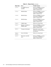
... board. 3-2 Dell PowerEdge 4100/180 and 4100/200 Systems Service Manual DRAM failure Defective DIMMs or system board. CMOS failure Defective system board. Unexpected interrupt Improperly seated expansion card, or system needs to be rebooted. Reseat DIMMs or replace system board. Beep Codes (continued) Error Probable Causes No DIMM memory installed Defective DIMMs or system board. Reseat DIMMs or replace system board. Reseat DIMMs or replace system board. Memory controller or DIMM failure Defective DIMMs or system board. Reseat DIMMs or replace system board. Beep...
... board. 3-2 Dell PowerEdge 4100/180 and 4100/200 Systems Service Manual DRAM failure Defective DIMMs or system board. CMOS failure Defective system board. Unexpected interrupt Improperly seated expansion card, or system needs to be rebooted. Reseat DIMMs or replace system board. Beep Codes (continued) Error Probable Causes No DIMM memory installed Defective DIMMs or system board. Reseat DIMMs or replace system board. Reseat DIMMs or replace system board. Memory controller or DIMM failure Defective DIMMs or system board. Reseat DIMMs or replace system board. Beep...
Service Manual
Page 39
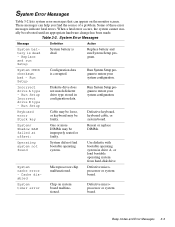
... bootable operating system from hard-disk drive. Use diskette with bootable operating system in configuration data. System Error Messages Table 3-2 lists system error messages that can help you find bootable operating system. These messages can appear on system board malfunctioned. Some of a problem. Table 3-2. System CMOS checksum bad - Incorrect drive A type - Defective keyboard, keyboard cable, or system board. System/ Shadow RAM failed at offset: One or more DIMMs may be rebooted until an appropriate hardware change has...
... bootable operating system from hard-disk drive. Use diskette with bootable operating system in configuration data. System Error Messages Table 3-2 lists system error messages that can help you find bootable operating system. These messages can appear on system board malfunctioned. Some of a problem. Table 3-2. System CMOS checksum bad - Incorrect drive A type - Defective keyboard, keyboard cable, or system board. System/ Shadow RAM failed at offset: One or more DIMMs may be rebooted until an appropriate hardware change has...
Service Manual
Page 51
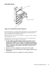
... the power on if a PowerEdge Expandable RAID Controller host adapter card is free of the drive bay. 4. Removing and Replacing Parts 4-9 To remove a hard-disk drive, follow these steps: NOTES: Wait 20 seconds for more information). Slide the drive carrier toward the front of the computer until the three indicators are mounted inside a hard-disk drive carrier. If a PowerEdge Expandable RAID Controller host adapter card is installed in the User's Guide for the hard-disk drive to Step 2. 2. Hard-Disk Drives drive bay plastic drive...
... the power on if a PowerEdge Expandable RAID Controller host adapter card is free of the drive bay. 4. Removing and Replacing Parts 4-9 To remove a hard-disk drive, follow these steps: NOTES: Wait 20 seconds for more information). Slide the drive carrier toward the front of the computer until the three indicators are mounted inside a hard-disk drive carrier. If a PowerEdge Expandable RAID Controller host adapter card is installed in the User's Guide for the hard-disk drive to Step 2. 2. Hard-Disk Drives drive bay plastic drive...
Service Manual
Page 65
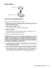
... setup screens. 2. WARNING: The new battery can explode if installed incorrectly. Removing and Replacing Parts 4-23 If possible, enter the System Setup program, and make a printed copy of its socket, and snap it into its socket with your fingers or with one of the removal procedure. Restore any system configuration information that was lost while replacing the battery. In addition, replace the old battery...
... setup screens. 2. WARNING: The new battery can explode if installed incorrectly. Removing and Replacing Parts 4-23 If possible, enter the System Setup program, and make a printed copy of its socket, and snap it into its socket with your fingers or with one of the removal procedure. Restore any system configuration information that was lost while replacing the battery. In addition, replace the old battery...
Service Manual
Page 71
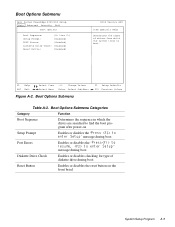
... or disables the " " message during boot Diskette Drive Check Enables or disables checking for type of diskette drive during boot Reset Button Enables or disables the reset button on the front bezel System Setup Program A-5 F1 Help ESC Exit Select Item Select Menu -/+ Change Values Enter Select Sub-Menu Figure A-2. Boot Options Submenu Dell System PowerEdge 4100/200 Setup Main Advanced Security Exit Boot Options Boot Sequence: [A: then C:] Setup Prompt: [Enabled] POST Errors: [Enabled] Diskette Drive Check: [Enabled] Reset Button: [Enabled] BIOS Version AXX Item Specific...
... or disables the " " message during boot Diskette Drive Check Enables or disables checking for type of diskette drive during boot Reset Button Enables or disables the reset button on the front bezel System Setup Program A-5 F1 Help ESC Exit Select Item Select Menu -/+ Change Values Enter Select Sub-Menu Figure A-2. Boot Options Submenu Dell System PowerEdge 4100/200 Setup Main Advanced Security Exit Boot Options Boot Sequence: [A: then C:] Setup Prompt: [Enabled] POST Errors: [Enabled] Diskette Drive Check: [Enabled] Reset Button: [Enabled] BIOS Version AXX Item Specific...
Service Manual
Page 81
...configuration, 1-12 connectors, 4-17 DC voltage ranges, 1-11 illustrated, 1-12 removal, 4-12 voltage output ranges, 1-11 POWER1 connector, 4-17 POWER2 connector, 4-17 power-supply paralleling board connector configuration, 1-16 illustrated, 1-16 removal, 4-13 precautions, 4-2 PROCESSOR1 connector, 4-17 PROCESSOR2 connector, 4-17 R REMOTE connector, 4-17 reset button location on I/O panel, 1-4 resource conflicts eliminating, 2-5 S SCSI BACKPLANE connector, 4-17 SCSI CD-ROM connector, 4-17 SCSI connectors, 4-17 SCSI controllers, integrated, 1-9 SCSI devices ID numbers, 1-10 SCSI hard-disk drives...
...configuration, 1-12 connectors, 4-17 DC voltage ranges, 1-11 illustrated, 1-12 removal, 4-12 voltage output ranges, 1-11 POWER1 connector, 4-17 POWER2 connector, 4-17 power-supply paralleling board connector configuration, 1-16 illustrated, 1-16 removal, 4-13 precautions, 4-2 PROCESSOR1 connector, 4-17 PROCESSOR2 connector, 4-17 R REMOTE connector, 4-17 reset button location on I/O panel, 1-4 resource conflicts eliminating, 2-5 S SCSI BACKPLANE connector, 4-17 SCSI CD-ROM connector, 4-17 SCSI connectors, 4-17 SCSI controllers, integrated, 1-9 SCSI devices ID numbers, 1-10 SCSI hard-disk drives...
Service Manual
Page 82
serial port connectors location on I/O panel, 1-7 location on system board, 4-17 server-management bus connector, 4-17 server-management serial port connector location on I/O panel, 1-7 location on system board, 4-17 SMB BACKPLANE connector, 4-17 sockets battery, 4-23 DIMM, 4-17, 4-19 specifications, technical, 1-24 subsystems advanced expansion, 1-8 main memory, 1-21 system board components, 4-17 illustrated, 1-20 jumpers, 1-21 location, 1-5 removing and replacing, 4-24 system board jumpers, 1-21 system error messages list of, 3-3 system features, 1-1 system power supply, 1-11 System Setup ...
serial port connectors location on I/O panel, 1-7 location on system board, 4-17 server-management bus connector, 4-17 server-management serial port connector location on I/O panel, 1-7 location on system board, 4-17 SMB BACKPLANE connector, 4-17 sockets battery, 4-23 DIMM, 4-17, 4-19 specifications, technical, 1-24 subsystems advanced expansion, 1-8 main memory, 1-21 system board components, 4-17 illustrated, 1-20 jumpers, 1-21 location, 1-5 removing and replacing, 4-24 system board jumpers, 1-21 system error messages list of, 3-3 system features, 1-1 system power supply, 1-11 System Setup ...


