Service Manual
Page 3
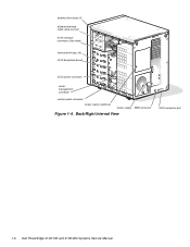
... The Pentium Pro microprocessor contains a built-in a traditional personal computer, Dell PowerEdge 4100 systems include the following new and/or advanced features: • 256 KB (PowerEdge 4100/180 systems) or 512 KB (PowerEdge 4100/200 systems) of cache memory internal to six hard-disk drives • ... of 60 MHz • Dell PowerEdge 4100/200 system - 200 MHz derived from a system clock frequency of 66 MHz System Features In addition to the standard features found in clock multiplier circuit, which allow you to integrate your servers. PowerEdge 4100 systems may have been designed ...
... The Pentium Pro microprocessor contains a built-in a traditional personal computer, Dell PowerEdge 4100 systems include the following new and/or advanced features: • 256 KB (PowerEdge 4100/180 systems) or 512 KB (PowerEdge 4100/200 systems) of cache memory internal to six hard-disk drives • ... of 60 MHz • Dell PowerEdge 4100/200 system - 200 MHz derived from a system clock frequency of 66 MHz System Features In addition to the standard features found in clock multiplier circuit, which allow you to integrate your servers. PowerEdge 4100 systems may have been designed ...

Service Manual
Page 4
...-ROM drive standard in this chapter. ages and temperatures, as well as the operation of system features, see the "Dell PowerEdge 4100 and 6100 Systems Rack Kit Installation Guide" (P/N 40722). 1-2 Dell PowerEdge 4100/180 and 4100/200 Systems Service Manual • Error correction code (ECC) feature built into the memory controller on the system board •... a bidirectional parallel port, two serial ports, and the diskette drive interface • Integrated ultra-wide and ultra-narrow SCSI controllers • Integrated server management circuitry that monitors critical system volt-
...-ROM drive standard in this chapter. ages and temperatures, as well as the operation of system features, see the "Dell PowerEdge 4100 and 6100 Systems Rack Kit Installation Guide" (P/N 40722). 1-2 Dell PowerEdge 4100/180 and 4100/200 Systems Service Manual • Error correction code (ECC) feature built into the memory controller on the system board •... a bidirectional parallel port, two serial ports, and the diskette drive interface • Integrated ultra-wide and ultra-narrow SCSI controllers • Integrated server management circuitry that monitors critical system volt-
Service Manual
Page 8
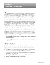
Back/Right Internal View SCSI connector port 1-6 Dell PowerEdge 4100/180 and 4100/200 Systems Service Manual external drive bays (4) diskette interface cable (ultra-narrow) SCSI interface connector (ultra-wide) internal drive bays (6) SCSI backplane board SCSI power connector server management connector control panel connector power supply (optional) power supply SMB connector Figure 1-4.
Back/Right Internal View SCSI connector port 1-6 Dell PowerEdge 4100/180 and 4100/200 Systems Service Manual external drive bays (4) diskette interface cable (ultra-narrow) SCSI interface connector (ultra-wide) internal drive bays (6) SCSI backplane board SCSI power connector server management connector control panel connector power supply (optional) power supply SMB connector Figure 1-4.
Service Manual
Page 10
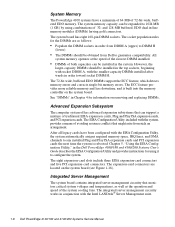
... and five PCI expansion-card connectors. and 128-MB buffered, EDO dual in conjunction with the Intel LANDesk® Server Management suite. 1-8 Dell PowerEdge 4100/180 and 4100/200 Systems Service Manual The 72-bit wide, buffered EDO DIMMs support the ECC feature, which detects memory errors and corrects... controller on the system board. The system board has eight 168-pin DIMM sockets. See "DIMMs" in the Dell PowerEdge 4100/180 and 4100/200 Systems User's Guide describes the EISA Configuration Utility and provides instructions for information on the system board (see Figure 1-18).
... and five PCI expansion-card connectors. and 128-MB buffered, EDO dual in conjunction with the Intel LANDesk® Server Management suite. 1-8 Dell PowerEdge 4100/180 and 4100/200 Systems Service Manual The 72-bit wide, buffered EDO DIMMs support the ECC feature, which detects memory errors and corrects... controller on the system board. The system board has eight 168-pin DIMM sockets. See "DIMMs" in the Dell PowerEdge 4100/180 and 4100/200 Systems User's Guide describes the EISA Configuration Utility and provides instructions for information on the system board (see Figure 1-18).
Service Manual
Page 22
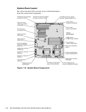
... connectors (EISA1 [top], EISA2, and EISA3) PCI connectors (PCI4 [top]-PCI8) battery connector (BATTERY) video connector (MONITOR) server-management serial port connector (REMOTE) parallel port connector (PARALLEL) serial port 2 connector (SERIAL2) serial port 1 connector (SERIAL1) ... socket (PROCESSOR1) power supply connector (POWER3) secondary microprocessor server-management bus socket (PROCESSOR2) connector (SMB BACKPLANE) Figure 1-18. System Board Components 1-20 Dell PowerEdge 4100/180 and 4100/200 Systems Service Manual System Board Layout The subsections that follow ...
... connectors (EISA1 [top], EISA2, and EISA3) PCI connectors (PCI4 [top]-PCI8) battery connector (BATTERY) video connector (MONITOR) server-management serial port connector (REMOTE) parallel port connector (PARALLEL) serial port 2 connector (SERIAL2) serial port 1 connector (SERIAL1) ... socket (PROCESSOR1) power supply connector (POWER3) secondary microprocessor server-management bus socket (PROCESSOR2) connector (SMB BACKPLANE) Figure 1-18. System Board Components 1-20 Dell PowerEdge 4100/180 and 4100/200 Systems Service Manual System Board Layout The subsections that follow ...
Service Manual
Page 28
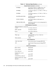
one 16-pin connector (server management) to CD-ROM SMB BACKPLANE. . . . . Technical Specifications (continued) System Board Connectors (continued) POWER1 one 18-pin connector: standby power, I2 C, PWRGOOD, and miscellaneous power ...
one 16-pin connector (server management) to CD-ROM SMB BACKPLANE. . . . . Technical Specifications (continued) System Board Connectors (continued) POWER1 one 18-pin connector: standby power, I2 C, PWRGOOD, and miscellaneous power ...
Service Manual
Page 34
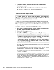
..., remove it from their power sources. 2. Grasp the card by its connector. Then reinstall the cardmounting bracket's retaining screw. 2-4 Dell PowerEdge 4100/180 and 4100/200 Systems Service Manual A simple visual inspection of a computer's interior hardware can get extremely hot. Be sure the chip has had sufficient...secures the card-mounting bracket. Remove the left computer cover. 3. Does the menu appear? Observe the monitor screen for the Dell Server Assistant Menu. Proceed to remove the screw that the chips are fully seated in this section, ensure that all the AC ...
..., remove it from their power sources. 2. Grasp the card by its connector. Then reinstall the cardmounting bracket's retaining screw. 2-4 Dell PowerEdge 4100/180 and 4100/200 Systems Service Manual A simple visual inspection of a computer's interior hardware can get extremely hot. Be sure the chip has had sufficient...secures the card-mounting bracket. Remove the left computer cover. 3. Does the menu appear? Observe the monitor screen for the Dell Server Assistant Menu. Proceed to remove the screw that the chips are fully seated in this section, ensure that all the AC ...
Service Manual
Page 36
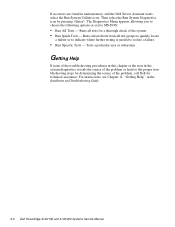
..., and the Dell Server Assistant loads, select the Run System Utilities icon. Runs selected tests from all tests for a thorough check of the problem, call Dell for determining the source of the system • Run Quick Tests - If no errors are found in the Installation and Troubleshooting Guide. 2-6 Dell PowerEdge 4100/180 and 4100/200 Systems Service Manual...
..., and the Dell Server Assistant loads, select the Run System Utilities icon. Runs selected tests from all tests for a thorough check of the problem, call Dell for determining the source of the system • Run Quick Tests - If no errors are found in the Installation and Troubleshooting Guide. 2-6 Dell PowerEdge 4100/180 and 4100/200 Systems Service Manual...

Service Manual
Page 41
... stepping or greater. Stepping of CPU1 is loose. Power supply paralleling board firmware download failed System backplane firmware download failed Server-management bus cable connection to system board (labeled "SMB BACKPLANE") and SCSI backplane (labeled "SMB"). Turn off and ...server management memory temporarily corrupted. Cache memory sizes of both microprocessors matches. Replace one of microprocessors so that cache size of the two Pentium Pro microprocessors do not match. System Error Messages (continued) Message Definition Action Stepping of CPU is neither 180 MHz or 200...
... stepping or greater. Stepping of CPU1 is loose. Power supply paralleling board firmware download failed System backplane firmware download failed Server-management bus cable connection to system board (labeled "SMB BACKPLANE") and SCSI backplane (labeled "SMB"). Turn off and ...server management memory temporarily corrupted. Cache memory sizes of both microprocessors matches. Replace one of microprocessors so that cache size of the two Pentium Pro microprocessors do not match. System Error Messages (continued) Message Definition Action Stepping of CPU is neither 180 MHz or 200...

Service Manual
Page 58
... the cooling fan from the fan carrier by server management; Press down the catch on . The middle fan is turned on the system board. 3. this fan is normally turned off by releasing the two fan retention tabs inside the carrier. 4-16 Dell PowerEdge 4100/180 and 4100/200 Systems Service Manual Disconnect the cooling fan's power...
... the cooling fan from the fan carrier by server management; Press down the catch on . The middle fan is turned on the system board. 3. this fan is normally turned off by releasing the two fan retention tabs inside the carrier. 4-16 Dell PowerEdge 4100/180 and 4100/200 Systems Service Manual Disconnect the cooling fan's power...

Service Manual
Page 80
..., 1-9 illustrated, 4-5 help, getting, 2-6 I indicator card removal, 4-11 initial procedures, 2-1 initialization error messages, 3-3 integrated features SCSI controllers, 1-9 server management, 1-8 video controller, 1-9 interrupt assignments list of, 1-22 ISA expansion cards, 4-18 J jumpers list of, 1-22 K KEYBOARD connector, 4-17 keyboard connector location on I/O panel, 1-7 location on system board, 4-17 2 Dell PowerEdge 4100/180 and 4100/200 Systems Service Manual
..., 1-9 illustrated, 4-5 help, getting, 2-6 I indicator card removal, 4-11 initial procedures, 2-1 initialization error messages, 3-3 integrated features SCSI controllers, 1-9 server management, 1-8 video controller, 1-9 interrupt assignments list of, 1-22 ISA expansion cards, 4-18 J jumpers list of, 1-22 K KEYBOARD connector, 4-17 keyboard connector location on I/O panel, 1-7 location on system board, 4-17 2 Dell PowerEdge 4100/180 and 4100/200 Systems Service Manual
Service Manual
Page 82
serial port connectors location on I/O panel, 1-7 location on system board, 4-17 server-management bus connector, 4-17 server-management serial port connector location on I/O panel, 1-7 location on system board, 4-17 SMB BACKPLANE connector, 4-17 sockets battery, 4-23 DIMM, 4-17, 4-19 specifications, technical, 1-24 ... SCSI host adapter connector, 4- 17 user contact, initial, 2-1 V video connector location on I/O panel, 1-7 location on system board, 4-17 video controller, integrated, 1-9 visual inspection external, 2-2 internal, 2-4 4 Dell PowerEdge 4100/180 and 4100/200 Systems Service Manual
serial port connectors location on I/O panel, 1-7 location on system board, 4-17 server-management bus connector, 4-17 server-management serial port connector location on I/O panel, 1-7 location on system board, 4-17 SMB BACKPLANE connector, 4-17 sockets battery, 4-23 DIMM, 4-17, 4-19 specifications, technical, 1-24 ... SCSI host adapter connector, 4- 17 user contact, initial, 2-1 V video connector location on I/O panel, 1-7 location on system board, 4-17 video controller, integrated, 1-9 visual inspection external, 2-2 internal, 2-4 4 Dell PowerEdge 4100/180 and 4100/200 Systems Service Manual


