Service Manual
Page 3
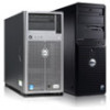
... to the standard features found in a traditional personal computer, Dell PowerEdge 4100 systems include the following new and/or advanced features: • 256 KB (PowerEdge 4100/180 systems) or 512 KB (PowerEdge 4100/200 systems) of cache memory internal to the Pentium Pro module ... Optional, redundant hot-pluggable power supplies System Overview 1-1 PowerEdge 4100 systems may have been designed for better serviceability and increased reliability, with optional redundant power supplies, RAID capability, hot-pluggable SCSI hard-disk drives, thermal and power supply monitoring, redundant ...
... to the standard features found in a traditional personal computer, Dell PowerEdge 4100 systems include the following new and/or advanced features: • 256 KB (PowerEdge 4100/180 systems) or 512 KB (PowerEdge 4100/200 systems) of cache memory internal to the Pentium Pro module ... Optional, redundant hot-pluggable power supplies System Overview 1-1 PowerEdge 4100 systems may have been designed for better serviceability and increased reliability, with optional redundant power supplies, RAID capability, hot-pluggable SCSI hard-disk drives, thermal and power supply monitoring, redundant ...

Service Manual
Page 4
... provides a bidirectional parallel port, two serial ports, and the diskette drive interface • Integrated ultra-wide and ultra-narrow SCSI controllers • Integrated server management circuitry that monitors critical system volt- • Error correction code (ECC) feature built into... New quick-test feature in the system diagnostics All of system features, see the "Dell PowerEdge 4100 and 6100 Systems Rack Kit Installation Guide" (P/N 40722). 1-2 Dell PowerEdge 4100/180 and 4100/200 Systems Service Manual For information about the Quick Test option in the CD-ROM based ...
... provides a bidirectional parallel port, two serial ports, and the diskette drive interface • Integrated ultra-wide and ultra-narrow SCSI controllers • Integrated server management circuitry that monitors critical system volt- • Error correction code (ECC) feature built into... New quick-test feature in the system diagnostics All of system features, see the "Dell PowerEdge 4100 and 6100 Systems Rack Kit Installation Guide" (P/N 40722). 1-2 Dell PowerEdge 4100/180 and 4100/200 Systems Service Manual For information about the Quick Test option in the CD-ROM based ...

Service Manual
Page 6
... and files if possible. reset button power button and power-on indicator diskette-drive access indicator (typical) SCSI hard-disk drive online indicator SCSI hard-disk drive fault indicator Figure 1-2. Before using MS-DOS®, the system can be used only when... restarting the system with a key combination fails. Front-Panel Features SCSI hard-disk drive activity indicator CAUTION: To avoid possible data or file structure corruptions, the frontpanel reset button should be rebooted by pressing . 1-4 Dell PowerEdge 4100/180 and 4100/200 Systems Service Manual
... and files if possible. reset button power button and power-on indicator diskette-drive access indicator (typical) SCSI hard-disk drive online indicator SCSI hard-disk drive fault indicator Figure 1-2. Before using MS-DOS®, the system can be used only when... restarting the system with a key combination fails. Front-Panel Features SCSI hard-disk drive activity indicator CAUTION: To avoid possible data or file structure corruptions, the frontpanel reset button should be rebooted by pressing . 1-4 Dell PowerEdge 4100/180 and 4100/200 Systems Service Manual
Service Manual
Page 8
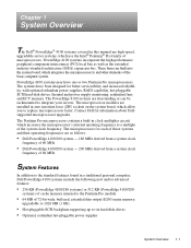
external drive bays (4) diskette interface cable (ultra-narrow) SCSI interface connector (ultra-wide) internal drive bays (6) SCSI backplane board SCSI power connector server management connector control panel connector power supply (optional) power supply SMB connector Figure 1-4. Back/Right Internal View SCSI connector port 1-6 Dell PowerEdge 4100/180 and 4100/200 Systems Service Manual
external drive bays (4) diskette interface cable (ultra-narrow) SCSI interface connector (ultra-wide) internal drive bays (6) SCSI backplane board SCSI power connector server management connector control panel connector power supply (optional) power supply SMB connector Figure 1-4. Back/Right Internal View SCSI connector port 1-6 Dell PowerEdge 4100/180 and 4100/200 Systems Service Manual
Service Manual
Page 11
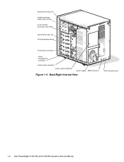
... externally accessible drives, see Chapter 10, "Installing Drives in the Internal Bays," in the Dell PowerEdge 4100/180 and 4100/200 Systems Installation and Troubleshooting Guide. Integrated SCSI Controllers A built-in Adaptec 7880 Ultra/Wide SCSI controller provides an ultra-wide fast SCSI interface via a 50-pin connector to the CD-ROM drive in the externally accessible drive...
... externally accessible drives, see Chapter 10, "Installing Drives in the Internal Bays," in the Dell PowerEdge 4100/180 and 4100/200 Systems Installation and Troubleshooting Guide. Integrated SCSI Controllers A built-in Adaptec 7880 Ultra/Wide SCSI controller provides an ultra-wide fast SCSI interface via a 50-pin connector to the CD-ROM drive in the externally accessible drive...
Service Manual
Page 12
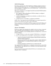
...in an externally accessible drive bay) is configured as SCSI ID 6. The other devices you are installed, connect the devices as the last device on disabling the device's terminator. 1-10 Dell PowerEdge 4100/180 and 4100/200 Systems Service Manual Disable the terminators on all devices ...in the Installation and Troubleshooting Guide. Therefore, any additional devices attached to the cable. SCSI ID Numbers Each device attached to the 7860...
...in an externally accessible drive bay) is configured as SCSI ID 6. The other devices you are installed, connect the devices as the last device on disabling the device's terminator. 1-10 Dell PowerEdge 4100/180 and 4100/200 Systems Service Manual Disable the terminators on all devices ...in the Installation and Troubleshooting Guide. Therefore, any additional devices attached to the cable. SCSI ID Numbers Each device attached to the 7860...
Service Manual
Page 22
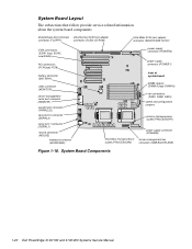
... adapter connector (FLOPPY) connector (SCSI2 CD-ROM) Ultra/Wide SCSI host adapter connector (BACKPLANE SCSI1) EISA connectors (EISA1 [top], EISA2, and EISA3) PCI connectors (PCI4 [top]-PCI8) battery connector (BATTERY) video ...(PROCESSOR1) power supply connector (POWER3) secondary microprocessor server-management bus socket (PROCESSOR2) connector (SMB BACKPLANE) Figure 1-18. System Board Components 1-20 Dell PowerEdge 4100/180 and 4100/200 Systems Service Manual System Board Layout The subsections that follow provide service-related information about the system board components.
... adapter connector (FLOPPY) connector (SCSI2 CD-ROM) Ultra/Wide SCSI host adapter connector (BACKPLANE SCSI1) EISA connectors (EISA1 [top], EISA2, and EISA3) PCI connectors (PCI4 [top]-PCI8) battery connector (BATTERY) video ...(PROCESSOR1) power supply connector (POWER3) secondary microprocessor server-management bus socket (PROCESSOR2) connector (SMB BACKPLANE) Figure 1-18. System Board Components 1-20 Dell PowerEdge 4100/180 and 4100/200 Systems Service Manual System Board Layout The subsections that follow provide service-related information about the system board components.
Service Manual
Page 28
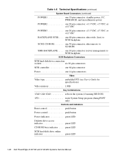
...) to CD-ROM SMB BACKPLANE. . . . . one 68-pin connector, ultra-wide (fast), to SCSI backplane SCSI2 CD-ROM one 50-pin connector, ultra-narrow, to SCSI backplane SCSI Backplane Connectors SCSI hard-disk drive connection sockets six 80-pin connectors SCSI controller one 68-pin connector Power one 20-pin connector: +3.3 VDC, +5 VDC, or +12...
...) to CD-ROM SMB BACKPLANE. . . . . one 68-pin connector, ultra-wide (fast), to SCSI backplane SCSI2 CD-ROM one 50-pin connector, ultra-narrow, to SCSI backplane SCSI Backplane Connectors SCSI hard-disk drive connection sockets six 80-pin connectors SCSI controller one 68-pin connector Power one 20-pin connector: +3.3 VDC, +5 VDC, or +12...
Service Manual
Page 29
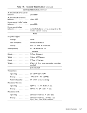
...) Weight 45 kg (100 lb) or more, depending on ; Technical Specifications (continued) Controls and Indicators (continued) SCSI hard-disk drive activity indicator green LED SCSI hard-disk drive fault indicator yellow LED Power-supply 5-VDC online indicator green LED Power-supply failure indicator red LED (flashes... at 3 to 200 Hz for 15 ms System Overview 1-27 square wave form: 27 G for 30 min Storage ...
...) Weight 45 kg (100 lb) or more, depending on ; Technical Specifications (continued) Controls and Indicators (continued) SCSI hard-disk drive activity indicator green LED SCSI hard-disk drive fault indicator yellow LED Power-supply 5-VDC online indicator green LED Power-supply failure indicator red LED (flashes... at 3 to 200 Hz for 15 ms System Overview 1-27 square wave form: 27 G for 30 min Storage ...

Service Manual
Page 41
... firmware download failed System backplane firmware download failed Server-management bus cable connection to system board (labeled "SMB BACKPLANE") and SCSI backplane (labeled "SMB"). System halted. The microprocessor speed detected is less than sA1 System halted. Beep Codes and Error .... Check speed jumpers. Check servermanagement bus cable connections to SCSI backplane board is less than sA1 System halted. Check microprocessor speed jumpers. Stepping of CPU is neither 180 MHz or 200 MHz. Replace microprocessor with correct sA1 stepping or greater. ...
... firmware download failed System backplane firmware download failed Server-management bus cable connection to system board (labeled "SMB BACKPLANE") and SCSI backplane (labeled "SMB"). System halted. The microprocessor speed detected is less than sA1 System halted. Beep Codes and Error .... Check speed jumpers. Check servermanagement bus cable connections to SCSI backplane board is less than sA1 System halted. Check microprocessor speed jumpers. Stepping of CPU is neither 180 MHz or 200 MHz. Replace microprocessor with correct sA1 stepping or greater. ...
Service Manual
Page 50
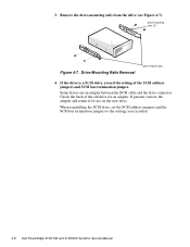
..., record the setting of the old drive for use an adapter between the SCSI cable and the drive connector. If present, remove the adapter and retain it for an adapter. Drive-Mounting Rails Removal drive-release ...Remove the drive-mounting rails from the drive (see Figure 4-7). drive-mounting rails (2) Figure 4-7. Check the back of the SCSI address jumpers and SCSI bus termination jumper. When reinstalling the SCSI drive, set the SCSI address jumpers and the SCSI bus termination jumpers to the settings you recorded. 4-8 Dell PowerEdge 4100/180 and 4100/200 Systems Service Manual
..., record the setting of the old drive for use an adapter between the SCSI cable and the drive connector. If present, remove the adapter and retain it for an adapter. Drive-Mounting Rails Removal drive-release ...Remove the drive-mounting rails from the drive (see Figure 4-7). drive-mounting rails (2) Figure 4-7. Check the back of the SCSI address jumpers and SCSI bus termination jumper. When reinstalling the SCSI drive, set the SCSI address jumpers and the SCSI bus termination jumpers to the settings you recorded. 4-8 Dell PowerEdge 4100/180 and 4100/200 Systems Service Manual
Service Manual
Page 56
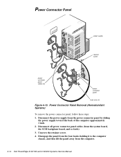
... approximately 1 inch. 2. Power Connector Panel Removal (Nonredundant Systems) To remove the power connector panel, follow these steps: 1. Disconnect the power supply from the computer. 4-14 Dell PowerEdge 4100/180 and 4100/200 Systems Service Manual Disconnect all power connector panel cables (from the system board, the SCSI backplane board, and so forth). 3.
... approximately 1 inch. 2. Power Connector Panel Removal (Nonredundant Systems) To remove the power connector panel, follow these steps: 1. Disconnect the power supply from the computer. 4-14 Dell PowerEdge 4100/180 and 4100/200 Systems Service Manual Disconnect all power connector panel cables (from the system board, the SCSI backplane board, and so forth). 3.
Service Manual
Page 72
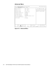
Advanced Menu Dell System PowerEdge 4100/200 Setup Main Advanced Security Exit Serial Port 1: Serial Port 2: Parallel Port: Parallel Mode: Diskette Controller: On-Board SCSI A: On-Board SCSI B: PCI Scan Sequence Use MP Specification PS/2 Mouse [3F8, IRQ 4] [2F8, IRQ 3] [378, IRQ 7] [Output only] [Enabled] [Enabled] {Enabled} [Embedded devices first] {1.4} [Enabled] BIOS.... F1 Help ESC Exit Select Item Select Menu -/+ Change Values Enter Select Sub-Menu Figure A-3. Advanced Menu F9 Setup Defaults F10 Previous Values A-6 Dell PowerEdge 4100/180 and 4100/200 Systems Service Manual
Advanced Menu Dell System PowerEdge 4100/200 Setup Main Advanced Security Exit Serial Port 1: Serial Port 2: Parallel Port: Parallel Mode: Diskette Controller: On-Board SCSI A: On-Board SCSI B: PCI Scan Sequence Use MP Specification PS/2 Mouse [3F8, IRQ 4] [2F8, IRQ 3] [378, IRQ 7] [Output only] [Enabled] [Enabled] {Enabled} [Embedded devices first] {1.4} [Enabled] BIOS.... F1 Help ESC Exit Select Item Select Menu -/+ Change Values Enter Select Sub-Menu Figure A-3. Advanced Menu F9 Setup Defaults F10 Previous Values A-6 Dell PowerEdge 4100/180 and 4100/200 Systems Service Manual

Service Manual
Page 80
... 1-23 drive bays external, 1-5, 1-6 internal, 1-5, 1-6 drives about, 1-25 illustrated, 4-5 SCSI configuration guidelines, 1-9 SCSI ID numbers, 1-10 SCSI termination jumpers, 1-10 E ECC, 1-8 EISA expansion cards, 1-8 EISA expansion-card connectors, 4-17..., 3-3 integrated features SCSI controllers, 1-9 server management, 1-8 video controller, 1-9 interrupt assignments list of, 1-22 ISA expansion cards, 4-18 J jumpers list of, 1-22 K KEYBOARD connector, 4-17 keyboard connector location on I/O panel, 1-7 location on system board, 4-17 2 Dell PowerEdge 4100/180 and 4100/200 Systems Service Manual
... 1-23 drive bays external, 1-5, 1-6 internal, 1-5, 1-6 drives about, 1-25 illustrated, 4-5 SCSI configuration guidelines, 1-9 SCSI ID numbers, 1-10 SCSI termination jumpers, 1-10 E ECC, 1-8 EISA expansion cards, 1-8 EISA expansion-card connectors, 4-17..., 3-3 integrated features SCSI controllers, 1-9 server management, 1-8 video controller, 1-9 interrupt assignments list of, 1-22 ISA expansion cards, 4-18 J jumpers list of, 1-22 K KEYBOARD connector, 4-17 keyboard connector location on I/O panel, 1-7 location on system board, 4-17 2 Dell PowerEdge 4100/180 and 4100/200 Systems Service Manual
Service Manual
Page 82
... routine, interpreting, 2-3 external visual inspection, 2-2 initial procedures, 2-1 initial user contact, 2-1 internal visual inspection, 2-4 U Ultra/Narrow SCSI host adapter connector, 4-17 Ultra/Wide SCSI host adapter connector, 4- 17 user contact, initial, 2-1 V video connector location on I/O panel, 1-7 location on system board, 4-17 video controller, integrated, 1-9 visual inspection external, 2-2 internal, 2-4 4 Dell PowerEdge 4100/180 and 4100/200 Systems Service Manual
... routine, interpreting, 2-3 external visual inspection, 2-2 initial procedures, 2-1 initial user contact, 2-1 internal visual inspection, 2-4 U Ultra/Narrow SCSI host adapter connector, 4-17 Ultra/Wide SCSI host adapter connector, 4- 17 user contact, initial, 2-1 V video connector location on I/O panel, 1-7 location on system board, 4-17 video controller, integrated, 1-9 visual inspection external, 2-2 internal, 2-4 4 Dell PowerEdge 4100/180 and 4100/200 Systems Service Manual


