Users Manual - English
Page 216
... be placed in the document feeder and fed one fax unit to communicate with your document. Beeper The sound the keys make when they are pressed, an error occurs, or a document has been received or transmitted (programmable). coding method Method of Modified Huffman (MH). Compatibility ...is assured between two calls. Glossary ADF (Automatic Document Feed) Refers to the number of pages that can be sent as one location. Automatic Redial...
... be placed in the document feeder and fed one fax unit to communicate with your document. Beeper The sound the keys make when they are pressed, an error occurs, or a document has been received or transmitted (programmable). coding method Method of Modified Huffman (MH). Compatibility ...is assured between two calls. Glossary ADF (Automatic Document Feed) Refers to the number of pages that can be sent as one location. Automatic Redial...
Users Manual - English
Page 217
...mode if you are stored on an existing phone line. Fax Storage The machine can use this code ( 51) when you to pick up a voice call that it is sending, receiving or printing... G - 2 Easy Receive Enables your machine to respond to program your machine. ECM (Error Correction Mode) Detects errors during fax transmission and resends the page(s) that day. FAX/TEL You can program a ...Ring A service purchased from an extension or external phone. The Brother machine uses the new number to another phone number on a One Touch key for copying and faxing photographs. F/T Ring Time The...
...mode if you are stored on an existing phone line. Fax Storage The machine can use this code ( 51) when you to pick up a voice call that it is sending, receiving or printing... G - 2 Easy Receive Enables your machine to respond to program your machine. ECM (Error Correction Mode) Detects errors during fax transmission and resends the page(s) that day. FAX/TEL You can program a ...Ring A service purchased from an extension or external phone. The Brother machine uses the new number to another phone number on a One Touch key for copying and faxing photographs. F/T Ring Time The...
Users Manual - English
Page 227
...One Touch numbers 7-5 pulse (rotary) (for Canada) 7-7 Speed Dial numbers 7-5 document jam 22-4 Drivers Windows printing 13-1 drum unit cleaning 22-17 installing 2-3 life remaining 22-22 replacing 22-21 Dual Access 6-3 E Easy Receive 5-3 ECM (Error Correction Mode) 1-6 entering text 4-3 envelopes printing 13-2 sizes 2-6 error... 22-1 COMM. ERROR 22-1 NOT REGISTERED 22-2 OUT OF MEMORY 22-2 while scanning a document 11-1 extension telephones, using 5-5 external telephone connecting 2-10 F fax codes Fax Receive Code 5-5 Remote Retrieval Access Code 9-3 Telephone Answer Code 5-5 troubleshooting 5-5 ...
...One Touch numbers 7-5 pulse (rotary) (for Canada) 7-7 Speed Dial numbers 7-5 document jam 22-4 Drivers Windows printing 13-1 drum unit cleaning 22-17 installing 2-3 life remaining 22-22 replacing 22-21 Dual Access 6-3 E Easy Receive 5-3 ECM (Error Correction Mode) 1-6 entering text 4-3 envelopes printing 13-2 sizes 2-6 error... 22-1 COMM. ERROR 22-1 NOT REGISTERED 22-2 OUT OF MEMORY 22-2 while scanning a document 11-1 extension telephones, using 5-5 external telephone connecting 2-10 F fax codes Fax Receive Code 5-5 Remote Retrieval Access Code 9-3 Telephone Answer Code 5-5 troubleshooting 5-5 ...
Users Manual - English
Page 229
...OCR 16-3 ScanSoft™ PaperPort 16-1 Search 7-4 simultaneous printing/fax 13-6 Sleep mode 4-8 Software for DOS users 12-1 using Brother Control Center 15-1 ScanSoft™ Paper Port® 16-1 software using ScanSoft™ PaperPort® TextBridge® OCR 16-1 ...connecting 2-10 receive mode 5-1 recording outgoing message 2-11 Telephone Answer Code 5-5 timer 6-9 toner cartridge installing 2-3 replacing 22-18 toner save 4-8 Transmission Verification Report 10-2 transparencies 2-5 troubleshooting document jam 22-4 error messages on LCD 22-1 if you are having difficulty DOS setup printing...
...OCR 16-3 ScanSoft™ PaperPort 16-1 Search 7-4 simultaneous printing/fax 13-6 Sleep mode 4-8 Software for DOS users 12-1 using Brother Control Center 15-1 ScanSoft™ Paper Port® 16-1 software using ScanSoft™ PaperPort® TextBridge® OCR 16-1 ...connecting 2-10 receive mode 5-1 recording outgoing message 2-11 Telephone Answer Code 5-5 timer 6-9 toner cartridge installing 2-3 replacing 22-18 toner save 4-8 Transmission Verification Report 10-2 transparencies 2-5 troubleshooting document jam 22-4 error messages on LCD 22-1 if you are having difficulty DOS setup printing...
Service Manual
Page 3
CHAPTER II. CHAPTER VI. Appendix 4. CHAPTER I. CHAPTER IV. CHAPTER V. EEPROM Customizing Codes Firmware Switches (WSW) Circuit Diagrams Toner Cartridge Weight This manual describes the models and their versions to ...is always in best condition for major countries. This manual is made up of the Brother facsimile equipment. Appendix 3. GENERAL DESCRIPTION INSTALLATION THEORY OF OPERATION DISASSEMBLY/REASSEMBLY AND LUBRICATION MAINTENANCE MODE ERROR INDICATION AND TROUBLESHOOTING Appendix 1. It includes information required for field troubleshooting and repair--disassembly,...
CHAPTER II. CHAPTER VI. Appendix 4. CHAPTER I. CHAPTER IV. CHAPTER V. EEPROM Customizing Codes Firmware Switches (WSW) Circuit Diagrams Toner Cartridge Weight This manual describes the models and their versions to ...is always in best condition for major countries. This manual is made up of the Brother facsimile equipment. Appendix 3. GENERAL DESCRIPTION INSTALLATION THEORY OF OPERATION DISASSEMBLY/REASSEMBLY AND LUBRICATION MAINTENANCE MODE ERROR INDICATION AND TROUBLESHOOTING Appendix 1. It includes information required for field troubleshooting and repair--disassembly,...
Service Manual
Page 112
... Scanning Start/End Position V-16 3.11 CIS Scanner Area Setting V-17 3.12 EEPROM Customizing V-17 3.13 Display of the Equipment's Log Information V-18 3.14 Equipment Error Code Indication V-19 3.15 Output of Transmission Log to the Telephone Line V-19 3.16 Cancellation of Control Panel PCB V-12 3.8 Receiver Volume Adjustment (applicable to the...
... Scanning Start/End Position V-16 3.11 CIS Scanner Area Setting V-17 3.12 EEPROM Customizing V-17 3.13 Display of the Equipment's Log Information V-18 3.14 Equipment Error Code Indication V-19 3.15 Output of Transmission Log to the Telephone Line V-19 3.16 Cancellation of Control Panel PCB V-12 3.8 Receiver Volume Adjustment (applicable to the...
Service Manual
Page 114
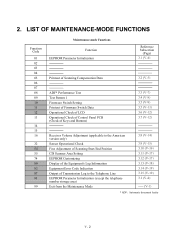
LIST OF MAINTENANCE-MODE FUNCTIONS Function Code 01 02 03 04 05 06 07 08 09 10 11 12 13 14 15 16 32 54 55 74 80 82 87 91 99 ... version only) Sensor Operational Check Fine Adjustment of Scanning Start/End Position CIS Scanner Area Setting EEPROM Customizing Display of the Equipment's Log Information Equipment Error Code Indication Output of Transmission Log to the Telephone Line EEPROM Parameter Initialization (except the telephone number storage area) Exit from the Maintenance Mode 3.8 (V-14) 3.9 (V-15...
LIST OF MAINTENANCE-MODE FUNCTIONS Function Code 01 02 03 04 05 06 07 08 09 10 11 12 13 14 15 16 32 54 55 74 80 82 87 91 99 ... version only) Sensor Operational Check Fine Adjustment of Scanning Start/End Position CIS Scanner Area Setting EEPROM Customizing Display of the Equipment's Log Information Equipment Error Code Indication Output of Transmission Log to the Telephone Line EEPROM Parameter Initialization (except the telephone number storage area) Exit from the Maintenance Mode 3.8 (V-14) 3.9 (V-15...
Service Manual
Page 129
... in the initial stage of the maintenance mode. If no keys are pressed for one minute in the initial stage of the maintenance mode. The newly entered code appears. The equipment saves the setting and returns to the initial stage of the maintenance mode, press the Stop key. 3.12 EEPROM ... to be sure to the initial stage of the maintenance mode. If any error is given in Appendix 1. The customizing codes list is noted, the "SCANNER ERROR" will appear on the LCD. NOTE: If you press the Stop key or no error is entered, the equipment will appear on the LCD. V - 17 ...
... in the initial stage of the maintenance mode. If no keys are pressed for one minute in the initial stage of the maintenance mode. The newly entered code appears. The equipment saves the setting and returns to the initial stage of the maintenance mode, press the Stop key. 3.12 EEPROM ... to be sure to the initial stage of the maintenance mode. If any error is given in Appendix 1. The customizing codes list is noted, the "SCANNER ERROR" will appear on the LCD. NOTE: If you press the Stop key or no error is entered, the equipment will appear on the LCD. V - 17 ...
Service Manual
Page 130
... is pressed, one of the following log information items appears on the LCD in the initial stage of the maintenance mode, press the Stop key. *1 When a machine error is displayed, pressing the Menu key toggles between the latest error and 2nd latest error. *2 When a communications error is displayed,... USB serial number appears on the MFC8500), indicating how many received FAX pages have been printed 11) Error code of the most recent machine error*1 12) Error code of the most recent communications error*2 13) ADF jam count, indicating how many times a document jam has been occurred 14) ADF ...
... is pressed, one of the following log information items appears on the LCD in the initial stage of the maintenance mode, press the Stop key. *1 When a machine error is displayed, pressing the Menu key toggles between the latest error and 2nd latest error. *2 When a communications error is displayed,... USB serial number appears on the MFC8500), indicating how many received FAX pages have been printed 11) Error code of the most recent machine error*1 12) Error code of the most recent communications error*2 13) ADF jam count, indicating how many times a document jam has been occurred 14) ADF ...
Service Manual
Page 131
... the user's equipment. Your equipment will start to your equipment for analyzing problems arising in the user's equipment. 3.14 Equipment Error Code Indication n Function This function displays an error code of your equipment. (2) If the line is connected, have the user perform the following: 1) Press the Menu, Mode,...the user's equipment at a remote location from the user's equipment, press the Fax Start key of the last error on the LCD. The LCD shows the "MACHINE ERROR X X." (2) To stop this order in this operation and return the equipment to the initial stage of the ...
... the user's equipment. Your equipment will start to your equipment for analyzing problems arising in the user's equipment. 3.14 Equipment Error Code Indication n Function This function displays an error code of your equipment. (2) If the line is connected, have the user perform the following: 1) Press the Menu, Mode,...the user's equipment at a remote location from the user's equipment, press the Fax Start key of the last error on the LCD. The LCD shows the "MACHINE ERROR X X." (2) To stop this order in this operation and return the equipment to the initial stage of the ...
Service Manual
Page 134
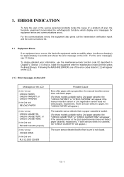
ERROR INDICATION AND TROUBLESHOOTING CONTENTS 1. TROUBLESHOOTING VI-17 2.1 Introduction ...VI-17 2.2 Precautions ...VI-17 2.3 Checking prior to Troubleshooting VI-17 2.4 Troubleshooting Procedures VI-19 [ 1 ] Control...3 ] Communications related VI-20 [ 4 ] Paper/document feeding related VI-20 [ 5 ] Print-image related VI-21 Location of High-voltage Contacts and Grounding Contacts VI-28 ERROR INDICATION VI-1 1.1 Equipment Errors VI-1 [ 1 ] Error messages on the LCD VI-1 [ 2 ] Error codes shown in the "MACHINE ERROR X X" message VI-5 1.2 Communications Errors VI-7 2. CHAPTER VI.
ERROR INDICATION AND TROUBLESHOOTING CONTENTS 1. TROUBLESHOOTING VI-17 2.1 Introduction ...VI-17 2.2 Precautions ...VI-17 2.3 Checking prior to Troubleshooting VI-17 2.4 Troubleshooting Procedures VI-19 [ 1 ] Control...3 ] Communications related VI-20 [ 4 ] Paper/document feeding related VI-20 [ 5 ] Print-image related VI-21 Location of High-voltage Contacts and Grounding Contacts VI-28 ERROR INDICATION VI-1 1.1 Equipment Errors VI-1 [ 1 ] Error messages on the LCD VI-1 [ 2 ] Error codes shown in the "MACHINE ERROR X X" message VI-5 1.2 Communications Errors VI-7 2. CHAPTER VI.
Service Manual
Page 135
... help the user or the service personnel promptly locate the cause of the error codes listed in Chapter V, Section 3.13 (that the front cover is loaded. (For those models available with a 2nd paper cassette, the "CHECK CASSETTE#1" or "CHECK CASSETTE... or the 2nd cassette sensor does not detect paper cassette, respectively. Following the MACHINE ERROR, one of a problem (if any), the facsimile equipment incorporates the self-diagnostic functions which display error messages for approximately 4 seconds and shows the error message on the LCD (In the 1st row) CHECK PAPER, CHECK PAPER#1, or ...
... help the user or the service personnel promptly locate the cause of the error codes listed in Chapter V, Section 3.13 (that the front cover is loaded. (For those models available with a 2nd paper cassette, the "CHECK CASSETTE#1" or "CHECK CASSETTE... or the 2nd cassette sensor does not detect paper cassette, respectively. Following the MACHINE ERROR, one of a problem (if any), the facsimile equipment incorporates the self-diagnostic functions which display error messages for approximately 4 seconds and shows the error message on the LCD (In the 1st row) CHECK PAPER, CHECK PAPER#1, or ...
Service Manual
Page 136
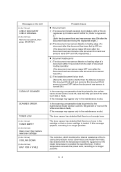
...toner sensor has detected that no toner in the maintenance mode.) In the scanning compensation data list printed by the maintenance-mode function code 05, fifty percent or more of the incasing temperature sensor (thermistor) and heater thermistor, has detected that the temperature inside the ... were OFF and ON, respectively.) n Document loading error (1) The document rear sensor detects no longer possible. The toner sensor has detected that there is no toner cartridge is not enough toner. VI - 2 The controller, which monitors the internal resistance of the white level data is faulty. ...
...toner sensor has detected that no toner in the maintenance mode.) In the scanning compensation data list printed by the maintenance-mode function code 05, fifty percent or more of the incasing temperature sensor (thermistor) and heater thermistor, has detected that the temperature inside the ... were OFF and ON, respectively.) n Document loading error (1) The document rear sensor detects no longer possible. The toner sensor has detected that there is no toner cartridge is not enough toner. VI - 2 The controller, which monitors the internal resistance of the white level data is faulty. ...
Service Manual
Page 137
... length (paper of approx. 3.15" long) or for one minute. (You can turn this message appears, open and ...by the maintenance-mode function code 10, WSW31, selector 8. Probable Cause The controller, which monitors the internal resistance of drum unit. ...error code, use maintenancemode function code 82. (Refer to [ 2 ] on the LCD (In the 1st row) WARMING UP (In the 2nd row) WAIT FOR A WHILE (In the 1st row) MACHINE ERROR XX (In the 2nd row) Unplug machine, then call Brother. Messages on pages VI-5 and VI-6. "XX" indicates an error code. If the error persists, the "MACHINE ERROR...
... length (paper of approx. 3.15" long) or for one minute. (You can turn this message appears, open and ...by the maintenance-mode function code 10, WSW31, selector 8. Probable Cause The controller, which monitors the internal resistance of drum unit. ...error code, use maintenancemode function code 82. (Refer to [ 2 ] on the LCD (In the 1st row) WARMING UP (In the 2nd row) WAIT FOR A WHILE (In the 1st row) MACHINE ERROR XX (In the 2nd row) Unplug machine, then call Brother. Messages on pages VI-5 and VI-6. "XX" indicates an error code. If the error persists, the "MACHINE ERROR...

Service Manual
Page 139
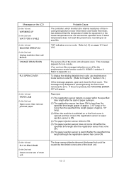
...detected by the document rear sensor. ) 50% or more faulty of white level data. ) Error codes in parentheses do not appear in the "MACHINE ERROR X X", since those error codes may be displayed. The registration sensor, 2nd registration sensor, and/or manual insertion sensor remains ON.)...the corona wire detected by the toner sensor. ) Paper size setting error. ) Paper feeding error. ) Paper jam. [ 2 ] Error codes shown in "[ 1 ] Error messages on the main PCB. ) Engine PCB error. ) Abnormal discharge of error 76 or 78. ) Heater thermistor short-circuited. Or heater thermistor harness...
...detected by the document rear sensor. ) 50% or more faulty of white level data. ) Error codes in parentheses do not appear in the "MACHINE ERROR X X", since those error codes may be displayed. The registration sensor, 2nd registration sensor, and/or manual insertion sensor remains ON.)...the corona wire detected by the toner sensor. ) Paper size setting error. ) Paper feeding error. ) Paper jam. [ 2 ] Error codes shown in "[ 1 ] Error messages on the main PCB. ) Engine PCB error. ) Abnormal discharge of error 76 or 78. ) Heater thermistor short-circuited. Or heater thermistor harness...
Service Manual
Page 140
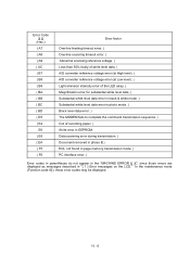
VI - 6 Error Code X X (Hex.) ( A7 ( A8 ( A9 ( AC ( B7 ( B8 ( B9 ( BA ( BB ( BC ( BD ( D5 ( E4 E6 ( E8 ( EA ( F5 ( F6 Error factor One-line feeding timeout error. ) One-line scanning timeout error. ) Abnormal scanning reference voltage. ) Less than 50% faulty of white level data. ) A/D converter reference voltage error (at High level). ) A/D converter reference voltage error (at Low level...
VI - 6 Error Code X X (Hex.) ( A7 ( A8 ( A9 ( AC ( B7 ( B8 ( B9 ( BA ( BB ( BC ( BD ( D5 ( E4 E6 ( E8 ( EA ( F5 ( F6 Error factor One-line feeding timeout error. ) One-line scanning timeout error. ) Abnormal scanning reference voltage. ) Less than 50% faulty of white level data. ) A/D converter reference voltage error (at High level). ) A/D converter reference voltage error (at Low level...

Service Manual
Page 142
Busy tone detected before start of Error Codes on the Communications List (1) Calling Code 1 10 10 10 11 11 11 11 11 11 11 Code 2 08 20 21 01 02 03 05 06 07 10 Causes Wrong number called . Overrun detected. No loop current detected.* Busy tone detected after...called . A frame for 7 bits or more received. Invalid command received. Command ignored once for document setting or for 200 ms or longer. Retrieval file error. Carrier was OFF for dumping-out at turn-around transmission. Undefined command received. VI - 8 No response from the calling station in receiving. 1A 01 ...
Busy tone detected before start of Error Codes on the Communications List (1) Calling Code 1 10 10 10 11 11 11 11 11 11 11 Code 2 08 20 21 01 02 03 05 06 07 10 Causes Wrong number called . Overrun detected. No loop current detected.* Busy tone detected after...called . A frame for 7 bits or more received. Invalid command received. Command ignored once for document setting or for 200 ms or longer. Retrieval file error. Carrier was OFF for dumping-out at turn-around transmission. Undefined command received. VI - 8 No response from the calling station in receiving. 1A 01 ...
Service Manual
Page 143
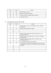
Image data file error. (3) Compatibility [checking the NSF and DIS] Code 1 32 32 Code 2 01 02 Causes Remote terminal only with or not ready for reception of the remote terminal is less than that required for relay broadcasting function. ... 12 Remote terminal not equipped with V.29 capability in the remote terminal. 32 14 The available memory space of the confidential or relay broadcasting instruction. Code 1 20 20 20 20 Code 2 0C 0D 10 11 Causes EOR and NULL received. Unable to reserve a command receiver memory.
Image data file error. (3) Compatibility [checking the NSF and DIS] Code 1 32 32 Code 2 01 02 Causes Remote terminal only with or not ready for reception of the remote terminal is less than that required for relay broadcasting function. ... 12 Remote terminal not equipped with V.29 capability in the remote terminal. 32 14 The available memory space of the confidential or relay broadcasting instruction. Code 1 20 20 20 20 Code 2 0C 0D 10 11 Causes EOR and NULL received. Unable to reserve a command receiver memory.
Service Manual
Page 150
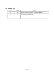
VI - 16 (14) Equipment error Code 1 FF FF Code 2 00 FF Causes Burn-in operation canceled by pressing the Stop key. Unrecoverable MODEM error.
VI - 16 (14) Equipment error Code 1 FF FF Code 2 00 FF Causes Burn-in operation canceled by pressing the Stop key. Unrecoverable MODEM error.
Service Manual
Page 159
... communications Check the following components: - l Instruct the user to Section 1, "ERROR INDICATION" in roller, separation roller, and their related sections - l Check the connection of the polygon motor harness on the laser unit. Error code displayed. (Refer to use the recommended types of the laser flat cable on the paper cassette(s). Document feed roller and its...
... communications Check the following components: - l Instruct the user to Section 1, "ERROR INDICATION" in roller, separation roller, and their related sections - l Check the connection of the polygon motor harness on the laser unit. Error code displayed. (Refer to use the recommended types of the laser flat cable on the paper cassette(s). Document feed roller and its...


