Service Manual
Page 3
..., and lubrication--so that the facsimile equipment is made up of the Brother facsimile equipment. CHAPTER II. GENERAL DESCRIPTION INSTALLATION THEORY OF OPERATION DISASSEMBLY/REASSEMBLY AND LUBRICATION MAINTENANCE MODE ERROR INDICATION AND TROUBLESHOOTING Appendix 1. To perform appropriate maintenance so that service personnel will be destined for the customer, the ...
..., and lubrication--so that the facsimile equipment is made up of the Brother facsimile equipment. CHAPTER II. GENERAL DESCRIPTION INSTALLATION THEORY OF OPERATION DISASSEMBLY/REASSEMBLY AND LUBRICATION MAINTENANCE MODE ERROR INDICATION AND TROUBLESHOOTING Appendix 1. To perform appropriate maintenance so that service personnel will be destined for the customer, the ...
Service Manual
Page 39
DISASSEMBLY/REASSEMBLY AND LUBRICATION CHAPTER IV.
DISASSEMBLY/REASSEMBLY AND LUBRICATION CHAPTER IV.
Service Manual
Page 40
... IV-1 n Safety Precautions IV-1 n Preparation...IV-2 n How to Access the Object Component IV-2 n Disassembly Order Flow IV-3 1.1 Rear Cover ...IV-4 1.2 Access Plates R and F IV-4 1.3 Control Panel ASSY IV-5 1.4 Panel Rear Cover and Control Panel IV-6 1.5 Document Feed Roller ASSY, ... Outer Chute and Paper Pinch Rollers IV-26 1.14 Main Cover ...IV-27 1.15 Switch Cover ...IV-28 1.16 Laser Unit ...IV-29 1.17 Heat-fixing Unit and FU Lamp IV-30 [Disassembling the heat-fixing unit IV-32 1.18 Fan ...IV-44 1.19 Drive Gear ASSY and Main Motor ASSY IV...
... IV-1 n Safety Precautions IV-1 n Preparation...IV-2 n How to Access the Object Component IV-2 n Disassembly Order Flow IV-3 1.1 Rear Cover ...IV-4 1.2 Access Plates R and F IV-4 1.3 Control Panel ASSY IV-5 1.4 Panel Rear Cover and Control Panel IV-6 1.5 Document Feed Roller ASSY, ... Outer Chute and Paper Pinch Rollers IV-26 1.14 Main Cover ...IV-27 1.15 Switch Cover ...IV-28 1.16 Laser Unit ...IV-29 1.17 Heat-fixing Unit and FU Lamp IV-30 [Disassembling the heat-fixing unit IV-32 1.18 Fan ...IV-44 1.19 Drive Gear ASSY and Main Motor ASSY IV...

Service Manual
Page 42
...maintenance jobs. Once removed, they will become unusable and new gears will have to be sure to cool down before working on the printer. DISASSEMBLY/REASSEMBLY n Safety Precautions To prevent the creation of the equipment to lose screws, washers, or other reflective objects in your eyes. (3) ... parts or units inside the machine. otherwise, the electronic parts may be careful not to the electricity charged in the path of the laser printing unit, be damaged due to place screwdrivers or other parts removed for parts replacement. (5) Do not remove gears from the power outlet...
...maintenance jobs. Once removed, they will become unusable and new gears will have to be sure to cool down before working on the printer. DISASSEMBLY/REASSEMBLY n Safety Precautions To prevent the creation of the equipment to lose screws, washers, or other reflective objects in your eyes. (3) ... parts or units inside the machine. otherwise, the electronic parts may be careful not to the electricity charged in the path of the laser printing unit, be damaged due to place screwdrivers or other parts removed for parts replacement. (5) Do not remove gears from the power outlet...
Service Manual
Page 43
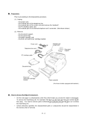
... You need to remove parts numbered , , , , , and so as to access the heat-fixing unit. • Unless otherwise specified, the disassembled parts or components should be reassembled in this case). the modular jack of removal. the document support, - the drum unit (with toner cartridge loaded) ...(*For those models equipped with handset.) n How to the disassembly procedure, (1) Unplug - the power cord, - the modular jack of an external telephone set if connected. (Not shown below.) (2) Remove - the ...
... You need to remove parts numbered , , , , , and so as to access the heat-fixing unit. • Unless otherwise specified, the disassembled parts or components should be reassembled in this case). the modular jack of removal. the document support, - the drum unit (with toner cartridge loaded) ...(*For those models equipped with handset.) n How to the disassembly procedure, (1) Unplug - the power cord, - the modular jack of an external telephone set if connected. (Not shown below.) (2) Remove - the ...
Service Manual
Page 44
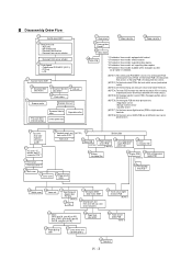
...(LED) PCB are a jam sensor and heater thermistor. (NOTE 4) The main PCB monitors the internal resistance of a control panel PCB and document sensor PCB. Heater roller - FU lamp (NOTE ...Fan 1.19 Drive gear ASSY - Document rear sensor actuator Document front sensor actuator 1.4 Control panel - n Disassembly Order Flow 1.3 Control panel ASSY 1.4 Panel rear cover - LCD 1.7 Scanner frame ASSY 1.5 Document feed roller...relay PCB *5 1.13 1.13 Outer chute Paper pinch rollers 1.15 1.16 Switch cover Laser unit 1.17 Heat-fixing unit - on the latter PCB is the document rear sensor. ...
...(LED) PCB are a jam sensor and heater thermistor. (NOTE 4) The main PCB monitors the internal resistance of a control panel PCB and document sensor PCB. Heater roller - FU lamp (NOTE ...Fan 1.19 Drive gear ASSY - Document rear sensor actuator Document front sensor actuator 1.4 Control panel - n Disassembly Order Flow 1.3 Control panel ASSY 1.4 Panel rear cover - LCD 1.7 Scanner frame ASSY 1.5 Document feed roller...relay PCB *5 1.13 1.13 Outer chute Paper pinch rollers 1.15 1.16 Switch cover Laser unit 1.17 Heat-fixing unit - on the latter PCB is the document rear sensor. ...
Service Manual
Page 63
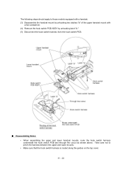
...; Make sure that the hook switch harness is routed along the guides on the top cover. Take care not to those models equipped with a handset: (3) Disassemble the handset mount by unhooking two latches "a" of the upper handset mount with a flat screwdriver. (4) Remove the hook switch PCB ASSY by unhooking latch "b." (5) Disconnect...
...; Make sure that the hook switch harness is routed along the guides on the top cover. Take care not to those models equipped with a handset: (3) Disassemble the handset mount by unhooking two latches "a" of the upper handset mount with a flat screwdriver. (4) Remove the hook switch PCB ASSY by unhooking latch "b." (5) Disconnect...
Service Manual
Page 73
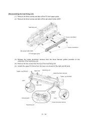
... unit. (4) Remove the two screws from the top of the heat-fixing unit. (5) Unlatch the upper FU frame from the lower one at each of the right and left ends. [Disassembling the heat-fixing unit] (1) Remove the three screws and take off the FU front paper guide. (2) Remove the three screws and...
... unit. (4) Remove the two screws from the top of the heat-fixing unit. (5) Unlatch the upper FU frame from the lower one at each of the right and left ends. [Disassembling the heat-fixing unit] (1) Remove the three screws and take off the FU front paper guide. (2) Remove the three screws and...
Service Manual
Page 100
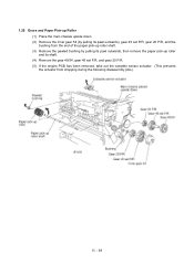
1.25 Gears and Paper Pick-up Roller (1) Place the main chassis upside down. (2) Remove the inner gear 54 (by pulling its pawl outwards), gear 45 set P/R, gear 20 P/R, and the bushing from the end of the paper pick-up roller shaft. (3) Remove the pawled bushing by pulling its pawl outwards, then remove the paper pick-up roller and its shaft. (4) Remove the gear 40/54, gear 45 set F/R, and gear 20 F/R. (5) If the engine PCB has been removed, take out the cassette sensor actuator. (This prevents the actuator from dropping during the following disassembly jobs.) IV - 59
1.25 Gears and Paper Pick-up Roller (1) Place the main chassis upside down. (2) Remove the inner gear 54 (by pulling its pawl outwards), gear 45 set P/R, gear 20 P/R, and the bushing from the end of the paper pick-up roller shaft. (3) Remove the pawled bushing by pulling its pawl outwards, then remove the paper pick-up roller and its shaft. (4) Remove the gear 40/54, gear 45 set F/R, and gear 20 F/R. (5) If the engine PCB has been removed, take out the cassette sensor actuator. (This prevents the actuator from dropping during the following disassembly jobs.) IV - 59


