Users Manual - English
Page 23
...not compatible with other features. Italics typeface emphasize an important point, or refer you the proper response for purchasing a Brother fax machine or multi-function center. Cautions specify procedures you must take to help you must follow or avoid to ...manual. For clarification, and to avoid possible personal injury. Warnings detail precautions you choose the correct key presses, we've added illustrations of some of Contents. INTRODUCTION 1-1 Press Reports, 1 to related topic. boldface italics bubble dot Bold typeface identifies a specific key...
...not compatible with other features. Italics typeface emphasize an important point, or refer you the proper response for purchasing a Brother fax machine or multi-function center. Cautions specify procedures you must take to help you must follow or avoid to ...manual. For clarification, and to avoid possible personal injury. Warnings detail precautions you choose the correct key presses, we've added illustrations of some of Contents. INTRODUCTION 1-1 Press Reports, 1 to related topic. boldface italics bubble dot Bold typeface identifies a specific key...
Users Manual - English
Page 38
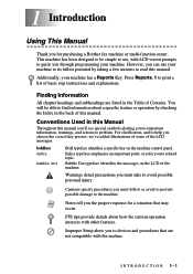
...hear CNG tones, the machine lets the TAD continue playing your outgoing message so your machine's Receive mode to control the phone line. (See illustration on the same telephone line as a fax number and set your caller can also connect a separate telephone (or telephone answering device) directly to...labeled EXT. The TAD must answer within four rings (the recommended setting is in the jack labeled EXT. If You Subscribe to your Brother machine. When you subscribe to connect an answering system. jack of the machine in use that you carefully follow the instructions in this ...
...hear CNG tones, the machine lets the TAD continue playing your outgoing message so your machine's Receive mode to control the phone line. (See illustration on the same telephone line as a fax number and set your caller can also connect a separate telephone (or telephone answering device) directly to...labeled EXT. The TAD must answer within four rings (the recommended setting is in the jack labeled EXT. If You Subscribe to your Brother machine. When you subscribe to connect an answering system. jack of the machine in use that you carefully follow the instructions in this ...

Users Manual - English
Page 116
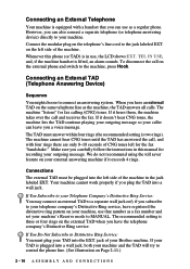
... 14 Printer Driver Settings 14 (For Windows® Only) Using the Brother MFC-8500 Printer Driver A Printer Driver is software that translates data from the Brother Solutions Center at http://solutions.brother.com. The latest printer driver can also change settings by a particular ... printer drivers are from Windows® 98. You can also be downloaded from the format used by a computer into the format required by clicking the illustration on your PC may vary depending on the left side of the tab screen. 14 - 1 P R I N T E R D R I V E R S E T T I N G S ( F O R W I N D O W S ® ...
... 14 Printer Driver Settings 14 (For Windows® Only) Using the Brother MFC-8500 Printer Driver A Printer Driver is software that translates data from the Brother Solutions Center at http://solutions.brother.com. The latest printer driver can also change settings by a particular ... printer drivers are from Windows® 98. You can also be downloaded from the format used by a computer into the format required by clicking the illustration on your PC may vary depending on the left side of the tab screen. 14 - 1 P R I N T E R D R I V E R S E T T I N G S ( F O R W I N D O W S ® ...
Users Manual - English
Page 128
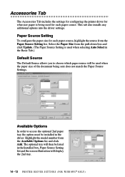
... configuring the printer driver for what size paper is used when selecting Auto Select in the Installed box, Paper Source Setting list and the screen illustration will display the 2nd tray. 14 - 13 P R I N T E R D R I V E R S E T T I N G S ( F O R W I N D O W S ® O N L Y ) Paper Source Setting To configure the paper size for each paper source. Select the Paper Size from...
... configuring the printer driver for what size paper is used when selecting Auto Select in the Installed box, Paper Source Setting list and the screen illustration will display the 2nd tray. 14 - 13 P R I N T E R D R I V E R S E T T I N G S ( F O R W I N D O W S ® O N L Y ) Paper Source Setting To configure the paper size for each paper source. Select the Paper Size from...
Users Manual - English
Page 212
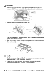
... cartridge carefully. HOT! 1 Open the front cover and pull out the drum unit. If toner scatters on the right as you use the machine, some internal parts of the machine will be extremely HOT! Place the used toner cartridge into the aluminum bag and discard it with cold water. 3 Unpack the... toner cartridge. WARNING Just after you pull the toner cartridge out of the drum unit assembly. So, never touch the shaded parts shown in the illustration.
... cartridge carefully. HOT! 1 Open the front cover and pull out the drum unit. If toner scatters on the right as you use the machine, some internal parts of the machine will be extremely HOT! Place the used toner cartridge into the aluminum bag and discard it with cold water. 3 Unpack the... toner cartridge. WARNING Just after you pull the toner cartridge out of the drum unit assembly. So, never touch the shaded parts shown in the illustration.
Quick Setup Guide for Windows XP - English
Page 1
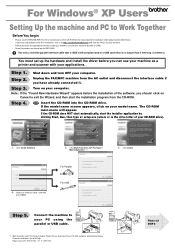
... information. • If you have any problems with this installation, visit us at http://solutions.brother.com and view the FAQ's for your machine. • Please purchase the appropriate interface cable ...to use your machine as a printer and scanner with this machine (parallel or USB). • Some illustrations are based on Cancel to exit the Wizard, and then start the installer application by clicking Start, Run,...Found New Hardware Wizard" appears before you should click on the MFC-8500. For Windows® XP Users Setting Up the machine and PC to Work Together Before You begin &#...
... information. • If you have any problems with this installation, visit us at http://solutions.brother.com and view the FAQ's for your machine. • Please purchase the appropriate interface cable ...to use your machine as a printer and scanner with this machine (parallel or USB). • Some illustrations are based on Cancel to exit the Wizard, and then start the installer application by clicking Start, Run,...Found New Hardware Wizard" appears before you should click on the MFC-8500. For Windows® XP Users Setting Up the machine and PC to Work Together Before You begin &#...
Service Manual
Page 24
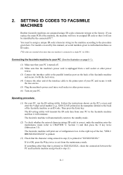
SETTING ID CODES TO FACSIMILE MACHINES Brother facsimile machines are essential when more than that the machine's power cord is OK, press the 9 key twice to exit from the maintenance mode. For ... secure it with the two screws. (5) Plug the machine's power cord into a wall socket or other than one machine is connected to a single PC via USB.) Connecting the facsimile machine to your PC (See the illustration on your PC, run the ID setting utility. II-3 Operating procedure (1) On your PC. 2. If something...
SETTING ID CODES TO FACSIMILE MACHINES Brother facsimile machines are essential when more than that the machine's power cord is OK, press the 9 key twice to exit from the maintenance mode. For ... secure it with the two screws. (5) Plug the machine's power cord into a wall socket or other than one machine is connected to a single PC via USB.) Connecting the facsimile machine to your PC (See the illustration on your PC, run the ID setting utility. II-3 Operating procedure (1) On your PC. 2. If something...
Service Manual
Page 37
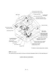
* Provided on the heat-fixing unit. Location of Sensors and Actuators III - 11 NOTE: Jam sensor The machine has a jam sensor (not shown in the above illustration) which is on models equipped with a handset.
* Provided on the heat-fixing unit. Location of Sensors and Actuators III - 11 NOTE: Jam sensor The machine has a jam sensor (not shown in the above illustration) which is on models equipped with a handset.
Service Manual
Page 68
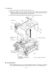
... cover from the rear side of a flat screwdriver, then lift up the main cover. Make sure that the cutout provided in the main cover, as illustrated above.
... cover from the rear side of a flat screwdriver, then lift up the main cover. Make sure that the cutout provided in the main cover, as illustrated above.
Service Manual
Page 82
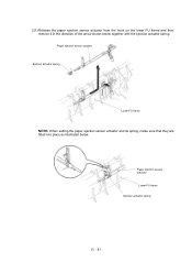
Paper ejection sensor actuator Ejection actuator spring Lower FU frame NOTE: When setting the paper ejection sensor actuator and its spring, make sure that they are fitted into place as illustrated below together with the ejection actuator spring. Paper ejection sensor actuator Lower FU frame Ejection actuator spring IV - 41 (21) Release the paper ejection sensor actuator from the hook on the lower FU frame and then remove it in the direction of the arrow shown below .
Paper ejection sensor actuator Ejection actuator spring Lower FU frame NOTE: When setting the paper ejection sensor actuator and its spring, make sure that they are fitted into place as illustrated below together with the ejection actuator spring. Paper ejection sensor actuator Lower FU frame Ejection actuator spring IV - 41 (21) Release the paper ejection sensor actuator from the hook on the lower FU frame and then remove it in the direction of the arrow shown below .
Service Manual
Page 89
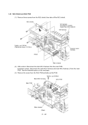
European version: Disconnect the main-NCU harness and main-NCU harness 2 from the main PCB. See the illustration given on the next page. (3) Remove the screw from the NCU PCB and take off the NCU shield. Taptite, cup S M3x6 (Tightening torque: 0.5 N•m) (2) USA version: Disconnect the main-NCU harness from the main PCB. 1.20 NCU Shield and NCU PCB (1) Remove three screws from the NCU shield, then take out the PCB. IV - 48
European version: Disconnect the main-NCU harness and main-NCU harness 2 from the main PCB. See the illustration given on the next page. (3) Remove the screw from the NCU PCB and take off the NCU shield. Taptite, cup S M3x6 (Tightening torque: 0.5 N•m) (2) USA version: Disconnect the main-NCU harness from the main PCB. 1.20 NCU Shield and NCU PCB (1) Remove three screws from the NCU shield, then take out the PCB. IV - 48
Service Manual
Page 90
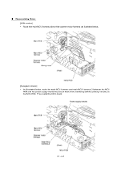
IV - 49 n Reassembling Notes [USA version] • Route the main-NCU harness above the scanner motor harness as illustrated below. [European version] • As illustrated below, route the main-NCU harness and main-NCU harness 2 between the NCU PCB and the power supply bracket to prevent them from interfering with the primary circuitry on the NCU PCB. Then install the NCU shield.
IV - 49 n Reassembling Notes [USA version] • Route the main-NCU harness above the scanner motor harness as illustrated below. [European version] • As illustrated below, route the main-NCU harness and main-NCU harness 2 between the NCU PCB and the power supply bracket to prevent them from interfering with the primary circuitry on the NCU PCB. Then install the NCU shield.
Service Manual
Page 93
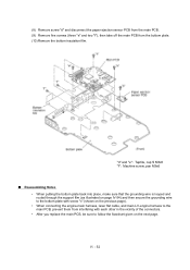
... Notes • When putting the bottom plate back into place, make sure that the grounding wire is looped and routed through the support film (as illustrated on page IV-54) and then secure the grounding wire to the bottom plate with each other in the vicinity of the connectors. • After... you replace the main PCB, be sure to follow the flowchart given on the previous page). • When connecting the engine-main harness, laser flat cable, and main-LV-engine harness to the main PCB, prevent them from the bottom plate. (10) Remove the bottom insulation film. (8) Remove screw...
... Notes • When putting the bottom plate back into place, make sure that the grounding wire is looped and routed through the support film (as illustrated on page IV-54) and then secure the grounding wire to the bottom plate with each other in the vicinity of the connectors. • After... you replace the main PCB, be sure to follow the flowchart given on the previous page). • When connecting the engine-main harness, laser flat cable, and main-LV-engine harness to the main PCB, prevent them from the bottom plate. (10) Remove the bottom insulation film. (8) Remove screw...
Service Manual
Page 99
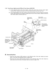
IV - 58 Reassembling Notes • Route the toner sensor (LED) harness on the toner sensor (LED) PCB with your fingers to the illustration given on page IV-56. • Route the toner sensor (light-receiver) harness on the right-hand side of the main chassis as shown above ...
IV - 58 Reassembling Notes • Route the toner sensor (LED) harness on the toner sensor (LED) PCB with your fingers to the illustration given on page IV-56. • Route the toner sensor (light-receiver) harness on the right-hand side of the main chassis as shown above ...
Service Manual
Page 124
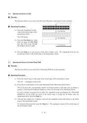
The equipment beeps for one second and returns to the initial stage of the maintenance mode. 3.7 Operational Check...operational check, press the Stop key. (3) After the last number key or button is correct by referring to the illustration below . To return to the status ready to accept key & button entry for normal operation. The equipment returns ...key or button is pressed. V - 12 The "00 " will appear on the LCD. To terminate this order in the illustration shown below . The LCD shows the corresponding number in decimal notation each time a key or button is pressed out of order...
The equipment beeps for one second and returns to the initial stage of the maintenance mode. 3.7 Operational Check...operational check, press the Stop key. (3) After the last number key or button is correct by referring to the illustration below . To return to the status ready to accept key & button entry for normal operation. The equipment returns ...key or button is pressed. V - 12 The "00 " will appear on the LCD. To terminate this order in the illustration shown below . The LCD shows the corresponding number in decimal notation each time a key or button is pressed out of order...
Service Manual
Page 155
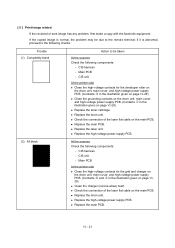
CIS harness - Main PCB - l Replace the laser unit. Main PCB At the printer side l Clean the high-voltage contacts for the developer roller on the drum unit, main cover, and high-voltage power supply PCB. (Contacts S in the illustration given on page VI-28) l Clean the grounding contacts... on the drum unit, main cover, and high-voltage power supply PCB. (Contacts Q in the illustration given on the main PCB. l Replace the main PCB. l Check the connection of the laser flat cable on page VI- 28) l Clean the charger (corona wires) itself. l Replace the main PCB...
CIS harness - Main PCB - l Replace the laser unit. Main PCB At the printer side l Clean the high-voltage contacts for the developer roller on the drum unit, main cover, and high-voltage power supply PCB. (Contacts S in the illustration given on page VI-28) l Clean the grounding contacts... on the drum unit, main cover, and high-voltage power supply PCB. (Contacts Q in the illustration given on the main PCB. l Replace the main PCB. l Check the connection of the laser flat cable on page VI- 28) l Clean the charger (corona wires) itself. l Replace the main PCB...
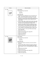
Service Manual
Page 156
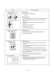
... the toner cartridge with a new one and print 4 to clean the corona wire inside the drum unit. l Clean the high-voltage contacts for the transfer roller on the drum unit, main cover, and high-voltage power supply PCB. (Contacts U in the illustration given on page VI-28) l... the scanner Check the following components: - l Remove the toner cartridge and start printing. l Replace the high-voltage power supply PCB. l Replace the laser unit. l Replace the drum unit. At the scanner Check the following components: - l Replace the high-voltage power supply PCB. VI - 22 If...
... the toner cartridge with a new one and print 4 to clean the corona wire inside the drum unit. l Clean the high-voltage contacts for the transfer roller on the drum unit, main cover, and high-voltage power supply PCB. (Contacts U in the illustration given on page VI-28) l... the scanner Check the following components: - l Remove the toner cartridge and start printing. l Replace the high-voltage power supply PCB. l Replace the laser unit. l Replace the drum unit. At the scanner Check the following components: - l Replace the high-voltage power supply PCB. VI - 22 If...
Service Manual
Page 157
...l If they appear at 79-mm intervals, replace the heat-fixing unit. l Clean the grounding contacts. (Contacts Q in the illustration given on the laser unit. l Replace the laser unit. (7) Black and blurred horizontal stripes (8) Horizontal lines At the printer side l Slide the wire cleaner to be contaminated with toner... inside the drum unit. l Slide the wire cleaner to its home position. l Replace the drum unit. At the printer side l Clean the laser beam window (glass) on page VI-29.) VI - 23 l If they appear at 39-mm intervals, replace the toner cartridge. At the ...
...l If they appear at 79-mm intervals, replace the heat-fixing unit. l Clean the grounding contacts. (Contacts Q in the illustration given on the laser unit. l Replace the laser unit. (7) Black and blurred horizontal stripes (8) Horizontal lines At the printer side l Slide the wire cleaner to be contaminated with toner... inside the drum unit. l Slide the wire cleaner to its home position. l Replace the drum unit. At the printer side l Clean the laser beam window (glass) on page VI-29.) VI - 23 l If they appear at 39-mm intervals, replace the toner cartridge. At the ...