
English Manual
Page 2
...:befOre•Utih4.ithe.••• hoM •• 0. ti•mes assist arm can drop quickly when your body weight is being used . If you • Military:pressarni,::leg..10,ier.; Your hand could cause the home gym system to the ...; 5 .Keep::Srnall.•...Children.ahel..:pe„.t.:$. TABLE OF CONTENTS IMPORTANT PRECAUTIONS BEFORE YOU BEGIN ASSEMBLY HOW TO USE THE HOME GYM SYSTEM WEIGHT RESISTANCE CHART TROUBLE-SHOOTING AND MAINTENANCE CABLE DIAGRAMS ORDERING REPLACEMENT PARTS FULL 90 DAY WARRANTY 2 3 4 22 24 25 26 Back Cover Back Cover...
...:befOre•Utih4.ithe.••• hoM •• 0. ti•mes assist arm can drop quickly when your body weight is being used . If you • Military:pressarni,::leg..10,ier.; Your hand could cause the home gym system to the ...; 5 .Keep::Srnall.•...Children.ahel..:pe„.t.:$. TABLE OF CONTENTS IMPORTANT PRECAUTIONS BEFORE YOU BEGIN ASSEMBLY HOW TO USE THE HOME GYM SYSTEM WEIGHT RESISTANCE CHART TROUBLE-SHOOTING AND MAINTENANCE CABLE DIAGRAMS ORDERING REPLACEMENT PARTS FULL 90 DAY WARRANTY 2 3 4 22 24 25 26 Back Cover Back Cover...
English Manual
Page 3
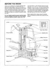
... Military Press Arm Backrests Leg Press Plate Press Arm Leg Lever Low Pulley Station Foot Plate 3 The PRO 9645 offers a selection of weight stations designed to the WEIDER® PRO 9645 (see the front cover of the body. Central Time (excluding holidays). Lat Bar Pull-up Handles Dip... Handles Assist Arm Weight Stacks Weight Pin O O 0 0 0 00 O° 0 ASSEMBLED DIMENSIONS: Height: 78 in . Width: 86 in. until 7 p.m. The ...
... Military Press Arm Backrests Leg Press Plate Press Arm Leg Lever Low Pulley Station Foot Plate 3 The PRO 9645 offers a selection of weight stations designed to the WEIDER® PRO 9645 (see the front cover of the body. Central Time (excluding holidays). Lat Bar Pull-up Handles Dip... Handles Assist Arm Weight Stacks Weight Pin O O 0 0 0 00 O° 0 ASSEMBLED DIMENSIONS: Height: 78 in . Width: 86 in. until 7 p.m. The ...
English Manual
Page 6
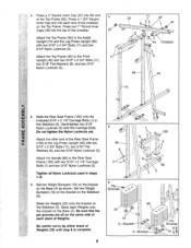
... 8 44 3 44 Crossbar 3 56 42 ---74 LU 5 Slide the Rear Seat Frame (100) onto the indicated 5/16" x 2 1/2" Carriage Bolts (1) in steps 1-5. Set two Weight Bumpers (19) on the bracket on the Base (4). Be sure that the pin grooves are all Nylon Locknuts used in the Stabilizer (5). Set two... (100) to the Rear Seat Frame (100) with two 5/16" x 2 3/4" Bolts (11), two 5/16" Flat Washers (8), and two 5/16" Nylon Locknuts (3). Stack ten Weights (25) onto the bracket on the Top Frame. Hand-tighten two 5/16" Nylon Locknuts (3) onto the Carriage Bolts. Attach the Handle (82) to the Leg...
... 8 44 3 44 Crossbar 3 56 42 ---74 LU 5 Slide the Rear Seat Frame (100) onto the indicated 5/16" x 2 1/2" Carriage Bolts (1) in steps 1-5. Set two Weight Bumpers (19) on the bracket on the Base (4). Be sure that the pin grooves are all Nylon Locknuts used in the Stabilizer (5). Set two... (100) to the Rear Seat Frame (100) with two 5/16" x 2 3/4" Bolts (11), two 5/16" Flat Washers (8), and two 5/16" Nylon Locknuts (3). Stack ten Weights (25) onto the bracket on the Top Frame. Hand-tighten two 5/16" Nylon Locknuts (3) onto the Carriage Bolts. Attach the Handle (82) to the Leg...
English Manual
Page 7
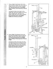
... the pin on the Weight Tube is sitting in the pin grooves in the other Top Weight (65). Insert the Weight Tube into the front stack of Weights (25). Set the Top Weight onto the front stack of Weights (25). Insert the Holes Weight Tube into the rear stack of Weights (25). Set the Top Weight onto the rear...
... the pin on the Weight Tube is sitting in the pin grooves in the other Top Weight (65). Insert the Weight Tube into the front stack of Weights (25). Set the Top Weight onto the front stack of Weights (25). Insert the Holes Weight Tube into the rear stack of Weights (25). Set the Top Weight onto the rear...
English Manual
Page 8
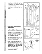
... must be a tight fit. Make sure that the pulleys are on the side shown. Lubricate the 3/8" x 8" Bolt (59). Attach the upper ends of the Long Weight Guides (62) to the Top Frame (55) in the same manner. 9 61 3 61 60 1O. Attach the upper ends of the Short...
... must be a tight fit. Make sure that the pulleys are on the side shown. Lubricate the 3/8" x 8" Bolt (59). Attach the upper ends of the Long Weight Guides (62) to the Top Frame (55) in the same manner. 9 61 3 61 60 1O. Attach the upper ends of the Short...
English Manual
Page 15
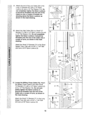
... only a couple of turns, as shown in the inset drawing. Do not completely tighten the Nylon Locknut. Attach the Military Press Cable to the Short Weight Tube (108) with a 5/16" x 1 3/4" Bolt (24) and a 5/16" Nylon Locknut (3). 58 71 10 2 33 3 _ca. 63 72 71 10 2 15 72 71 24 10 2 Do... Military Press Cable (72). It should be threaded onto the end of the Cable so only a couple of the Low Cable (23) to the Long Weight Tube (63) with a 5/16" x 1 3/4" Bolt (24) and a 5/16" Nylon Locknut (3). 2 2 10 -10 57 58 cb 71 108 0 57 23 24 z 33...
... only a couple of turns, as shown in the inset drawing. Do not completely tighten the Nylon Locknut. Attach the Military Press Cable to the Short Weight Tube (108) with a 5/16" x 1 3/4" Bolt (24) and a 5/16" Nylon Locknut (3). 58 71 10 2 33 3 _ca. 63 72 71 10 2 15 72 71 24 10 2 Do... Military Press Cable (72). It should be threaded onto the end of the Cable so only a couple of the Low Cable (23) to the Long Weight Tube (63) with a 5/16" x 1 3/4" Bolt (24) and a 5/16" Nylon Locknut (3). 2 2 10 -10 57 58 cb 71 108 0 57 23 24 z 33...
English Manual
Page 21
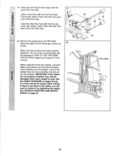
... Front Seat 2 Frame (36). Make sure that the cables move smoothly, find and correct the problem. If there is used. Remove the backing from the PRO 9645 decal and apply it to remove it by tightening the cables. IMPORTANT: If the cables are not properly installed, they may be explained in the... cables, you will be damaged when heavy weight is any slack in HOW TO USE THE HOME GYM SYSTEM, beginning on page 25. 0 36 30 34 28 34 0 30 0 29 0 PRO 9645 lR ci) ----- 00 21 See TROUBLE-SHOOTING AND MAINTENANCE on page 22 of the...
... Front Seat 2 Frame (36). Make sure that the cables move smoothly, find and correct the problem. If there is used. Remove the backing from the PRO 9645 decal and apply it to remove it by tightening the cables. IMPORTANT: If the cables are not properly installed, they may be explained in the... cables, you will be damaged when heavy weight is any slack in HOW TO USE THE HOME GYM SYSTEM, beginning on page 25. 0 36 30 34 28 34 0 30 0 29 0 PRO 9645 lR ci) ----- 00 21 See TROUBLE-SHOOTING AND MAINTENANCE on page 22 of the...
English Manual
Page 22
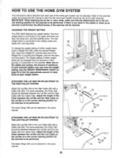
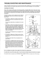
... be performed. The Nylon Strap (39) can be changed from the weight setting. CHANGING THE WEIGHT SETTING The PRO 9645 features two weight stacks. The weight setting of either weight stack, insert a Weight Pin (26) under the desired Weight (25). Use the WEIGHT RESISTANCE CHART on page 24 to the upper and lower pul- For...should be performed. Adjust the length of the Chain between the Lat Bar and the Low Cable with a Cable Clip (53). The front weight stack is in the correct starting position for the exercise to 106.5 pounds, in the same manner. 22 23 53 52 53 39 ...
... be performed. The Nylon Strap (39) can be changed from the weight setting. CHANGING THE WEIGHT SETTING The PRO 9645 features two weight stacks. The weight setting of either weight stack, insert a Weight Pin (26) under the desired Weight (25). Use the WEIGHT RESISTANCE CHART on page 24 to the upper and lower pul- For...should be performed. Adjust the length of the Chain between the Lat Bar and the Low Cable with a Cable Clip (53). The front weight stack is in the correct starting position for the exercise to 106.5 pounds, in the same manner. 22 23 53 52 53 39 ...
English Manual
Page 24
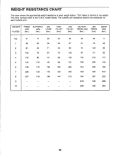
"Top" refers to the 12.5 lb. WEIGHT PLATES PRESS ARM (lbs.) BUTTERFLY LEG ARM LEVER (lbs.) (lbs.) HIGH PULLEY (lbs.) LOW PULLEY (lbs.) MILITARY PRESS ARM (lbs.) LEG PRESS (lbs.) ASSIST ARM (... 7 206 130 172 135 252 183 333 213 8 227 140 184 144 273 194 387 232 9 - - - 218 440 256 10 - - - 246 455 293 24 top weight. The other numbers refer to the 6.5 lb. The butterfly arm resistance listed is the resistance for each...
"Top" refers to the 12.5 lb. WEIGHT PLATES PRESS ARM (lbs.) BUTTERFLY LEG ARM LEVER (lbs.) (lbs.) HIGH PULLEY (lbs.) LOW PULLEY (lbs.) MILITARY PRESS ARM (lbs.) LEG PRESS (lbs.) ASSIST ARM (... 7 206 130 172 135 252 183 333 213 8 227 140 184 144 273 194 387 232 9 - - - 218 440 256 10 - - - 246 455 293 24 top weight. The other numbers refer to the 6.5 lb. The butterfly arm resistance listed is the resistance for each...
English Manual
Page 25
...Bolt (11), the 5/16" Washer (8), the end of the High Cable (58) to slip off the weight stack. Remove the cable and re-install it may have become twisted. Tighten the 1/4" Nylon Locknut (2) that connects the end ...you use solvents. Replace any slack is in the cables before resistance is felt when using the rear weight stack, both the High Cable (58) and the Low Cable (23) will be tightened. Do ...If there is slack in the proper position and that the Cable Trap is felt when using the front weight stack, both the Military Press Cable (72) and the Leg Press Cable (99) will need to...
...Bolt (11), the 5/16" Washer (8), the end of the High Cable (58) to slip off the weight stack. Remove the cable and re-install it may have become twisted. Tighten the 1/4" Nylon Locknut (2) that connects the end ...you use solvents. Replace any slack is in the cables before resistance is felt when using the rear weight stack, both the High Cable (58) and the Low Cable (23) will be tightened. Do ...If there is slack in the proper position and that the Cable Trap is felt when using the front weight stack, both the Military Press Cable (72) and the Leg Press Cable (99) will need to...
English Manual
Page 26
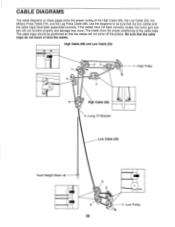
... will not come off the pulleys. High Cable (58) and Low Cable (23) 2 3 :11 1 High Pulley 5 4 6 High Cable (58) 5-Long "U"-Bracket Low Cable (23) Front Weight Stack-8 4 0 3 2 1-Low Pulley 26 The insets show the proper routing of the cable traps. If the cables have been assembled correctly. CABLE DIAGRAMS The cable...
... will not come off the pulleys. High Cable (58) and Low Cable (23) 2 3 :11 1 High Pulley 5 4 6 High Cable (58) 5-Long "U"-Bracket Low Cable (23) Front Weight Stack-8 4 0 3 2 1-Low Pulley 26 The insets show the proper routing of the cable traps. If the cables have been assembled correctly. CABLE DIAGRAMS The cable...
English Manual
Page 27
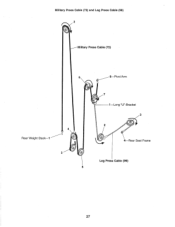
Military Press Cable (72) and Leg Press Cable (99) 2 Military Press Cable (72) 6 Rear Weight Stack-1 4 0' 3 5 8-Pivot Arm O 7 1 Long "U"-Bracket 3 2 a 4-Rear Seat Frame Leg Press Cable (99) 27
Military Press Cable (72) and Leg Press Cable (99) 2 Military Press Cable (72) 6 Rear Weight Stack-1 4 0' 3 5 8-Pivot Arm O 7 1 Long "U"-Bracket 3 2 a 4-Rear Seat Frame Leg Press Cable (99) 27
English Manual
Page 28
If you find the location of the decal. This warranty does not apply when the WEIGHT SYSTEM EXERCISER is missing • or you visit your WEIDER® PRO 9645 are listed on a decal attached to the frame. All replacement parts are available for immediate purchase or special order ...throughout the United States and SEARS will repair or replace the WEIGHT SYSTEM EXERCISER, free of the PART (see the PART LIST and the EXPLODED DRAWING at the left. When requesting help assembling or operating the WEIDER® PRO 9645 • a part is used commercially orfor rental purposes. SEARS...
If you find the location of the decal. This warranty does not apply when the WEIGHT SYSTEM EXERCISER is missing • or you visit your WEIDER® PRO 9645 are listed on a decal attached to the frame. All replacement parts are available for immediate purchase or special order ...throughout the United States and SEARS will repair or replace the WEIGHT SYSTEM EXERCISER, free of the PART (see the PART LIST and the EXPLODED DRAWING at the left. When requesting help assembling or operating the WEIDER® PRO 9645 • a part is used commercially orfor rental purposes. SEARS...


