
English Manual
Page 11
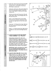
...the Left Pull-up Arm (75) with im soapy water. During steps 19 through 39, refer to the CABLE DIAGRAMS on the indicated side of the Cables. The pulleys must be able to verify proper cable routing. Attach the Left Pull-up Arm (75) and the Right Pull-up Arm (77) to the Assist... Arm (79) to the Assist Upright (74) with two 5/16" x 2 3/4" Bolts (11) and two 5/16" Nylon Locknuts (3). Wrap the High Cable around a 3 1/2" Pulley (15). Locate the High Cable (58). Press a1 1/4" Round Inner Cap (109) into the Left Dip Arm (78), and into the Right Pull-up Arm (77), onto...
...the Left Pull-up Arm (75) with im soapy water. During steps 19 through 39, refer to the CABLE DIAGRAMS on the indicated side of the Cables. The pulleys must be able to verify proper cable routing. Attach the Left Pull-up Arm (75) and the Right Pull-up Arm (77) to the Assist... Arm (79) to the Assist Upright (74) with two 5/16" x 2 3/4" Bolts (11) and two 5/16" Nylon Locknuts (3). Wrap the High Cable around a 3 1/2" Pulley (15). Locate the High Cable (58). Press a1 1/4" Round Inner Cap (109) into the Left Dip Arm (78), and into the Right Pull-up Arm (77), onto...
English Manual
Page 12
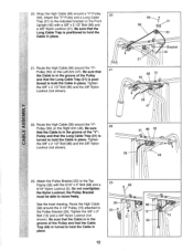
... 20 . ' 12 Bolt (12) and a 3/8" Nylon Locknut (not 3 \\\ 15 shown). Be sure that the Cable Trap (66) is turned to the Pulley Bracket (20). place. 12 Route the High Cable 55 66 (58) around the "V"Pulley (50) on the Left Arm (47). Do not overtighten the Nylon Locknut... a 3/8" x 2 1/2" Bolt (86) and a 3/8" Nylon Locknut (21). Be sure 22 that the Long Cable Trap (31) is posi- Route the High Cable (58) around a "V"-Pulley 20 (50). Be sure that 21 the Cable is in place. Tighten the 3/8" x 2 1/2" Bolt (86) and the 3/8" Nylon Locknut (not shown). 31...
... 20 . ' 12 Bolt (12) and a 3/8" Nylon Locknut (not 3 \\\ 15 shown). Be sure that the Cable Trap (66) is turned to the Pulley Bracket (20). place. 12 Route the High Cable 55 66 (58) around the "V"Pulley (50) on the Left Arm (47). Do not overtighten the Nylon Locknut... a 3/8" x 2 1/2" Bolt (86) and a 3/8" Nylon Locknut (21). Be sure 22 that the Long Cable Trap (31) is posi- Route the High Cable (58) around a "V"-Pulley 20 (50). Be sure that 21 the Cable is in place. Tighten the 3/8" x 2 1/2" Bolt (86) and the 3/8" Nylon Locknut (not shown). 31...
English Manual
Page 13
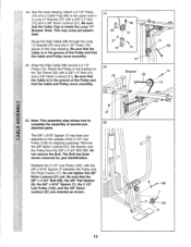
See the inset drawing. Route the High Cable (58) through the Long "U"-Bracket (57) and the 3 1/2" Pulley (15) shown in the groove of the Pulley and that the Cable is in a Long "U"-Bracket (57) with a 3/8" x 2" Bolt (12) and a 3/8" Nylon Locknut (21). 24. Be sure that the 3/8" x 3 3/4" Bolt (88), the 3/8" Flat Washer (9),... remove the Bolt. The Bolt has been shown removed for shipping purposes. Note: This may come pre-assembled. Be sure that the Cable Trap is in the inset drawing. Note: This assembly step shows how to the bracket on the outside of several pre- 26 attached...
See the inset drawing. Route the High Cable (58) through the Long "U"-Bracket (57) and the 3 1/2" Pulley (15) shown in the groove of the Pulley and that the Cable is in a Long "U"-Bracket (57) with a 3/8" x 2" Bolt (12) and a 3/8" Nylon Locknut (21). 24. Be sure that the 3/8" x 3 3/4" Bolt (88), the 3/8" Flat Washer (9),... remove the Bolt. The Bolt has been shown removed for shipping purposes. Note: This may come pre-assembled. Be sure that the Cable Trap is in the inset drawing. Note: This assembly step shows how to the bracket on the outside of several pre- 26 attached...

English Manual
Page 14
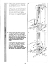
... turned to the lower hole in place and that the Cable Trap (66) is turned to hold the Cable in the 30 Front Upright (42). Be sure that the Cable is routed around the Pulley as shown. Route the Low 27 Cable under the 3 1/2" Low Pulley (102). Tighten the 3/8" Nylon Locknut (21)...23 /® 15 ® 21 66 17 30. Route the Low Cable (23) around the 3 1/2" Pulley (15) attached to hold the Cable in the 29 Press Frame (17). Route the Low Cable (23) around the 3 1/2" Pulley (15) attached to hold the Cable in the 28 Front Upright (42). Tighten the 3/8" Nylon...
... turned to the lower hole in place and that the Cable Trap (66) is turned to hold the Cable in the 30 Front Upright (42). Be sure that the Cable is routed around the Pulley as shown. Route the Low 27 Cable under the 3 1/2" Low Pulley (102). Tighten the 3/8" Nylon Locknut (21)...23 /® 15 ® 21 66 17 30. Route the Low Cable (23) around the 3 1/2" Pulley (15) attached to hold the Cable in the 29 Press Frame (17). Route the Low Cable (23) around the 3 1/2" Pulley (15) attached to hold the Cable in the 28 Front Upright (42). Tighten the 3/8" Nylon...
English Manual
Page 16
... 21-er 86 72 21 15 Bracket uJ U) 35. Be sure that the Long Cable Trap is between the Pulley and the Assist Arm and that the Cable is routed around the Pulley as shown. Wrap the Military Press Cable (72) around a 3 1/2" Pulley (15). Attach the "V"-Pulley to the Top Frame (55)... with a 3/8" x 1 3/4" Bolt (76) and a 3/8" Nylon Locknut (21). Be sure that the Cable is turned to the indicated...
... 21-er 86 72 21 15 Bracket uJ U) 35. Be sure that the Long Cable Trap is between the Pulley and the Assist Arm and that the Cable is routed around the Pulley as shown. Wrap the Military Press Cable (72) around a 3 1/2" Pulley (15). Attach the "V"-Pulley to the Top Frame (55)... with a 3/8" x 1 3/4" Bolt (76) and a 3/8" Nylon Locknut (21). Be sure that the Cable is turned to the indicated...
English Manual
Page 17
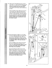
... 12 93 72 11 17 Be sure that the Pulley is on the side shown and that the Cable Trap is inside the Long "U"-Bracket. (Note: This may come preassembled.) Route the Military Press Cable (72) through the indicated hole in a Long "U"-Bracket (57) with the 3/8" x 3 3/4" Bolt (88), a ...3/8" Flat Washer (9), and a 3/8" Nylon Locknut (21). Be sure that the Cable Trap is positioned to the upper hole in the Pivot...
... 12 93 72 11 17 Be sure that the Pulley is on the side shown and that the Cable Trap is inside the Long "U"-Bracket. (Note: This may come preassembled.) Route the Military Press Cable (72) through the indicated hole in a Long "U"-Bracket (57) with the 3/8" x 3 3/4" Bolt (88), a ...3/8" Flat Washer (9), and a 3/8" Nylon Locknut (21). Be sure that the Cable Trap is positioned to the upper hole in the Pivot...
English Manual
Page 21
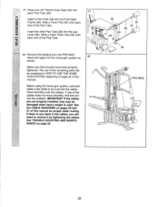
... be damaged when heavy weight is any slack in HOW TO USE THE HOME GYM SYSTEM, beginning on page 22 of this manual for proper cable routing. The use of the remaining parts will need to the home gym system as 48 shown. If one of the Pad Tube. 48. 47. ci...) Insert the other Pad Tube (28) into the Front Seat 2 Frame (36). Remove the backing from the PRO 9645 decal and apply it to remove it by tightening the cables. If there is used. Make sure that the cables move smoothly, find and correct the problem. Press two 3/4" Round Inner Caps (34) into each...
... be damaged when heavy weight is any slack in HOW TO USE THE HOME GYM SYSTEM, beginning on page 22 of this manual for proper cable routing. The use of the remaining parts will need to the home gym system as 48 shown. If one of the Pad Tube. 48. 47. ci...) Insert the other Pad Tube (28) into the Front Seat 2 Frame (36). Remove the backing from the PRO 9645 decal and apply it to remove it by tightening the cables. If there is used. Make sure that the cables move smoothly, find and correct the problem. Press two 3/4" Round Inner Caps (34) into each...
English Manual
Page 26
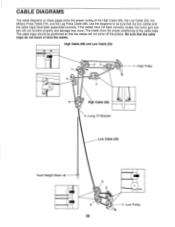
... insets show the proper routing of the cable traps. CABLE DIAGRAMS The cable diagrams on these pages show the proper positioning of the High Cable (58), the Low Cable (23), the Military Press Cable (72), and the Leg Press Cable (99). High Cable (58) and Low Cable (23) 2 3 :11 1 High Pulley 5 4 6 High Cable (58) 5-Long "U"-Bracket Low Cable (23) Front Weight Stack...
... insets show the proper routing of the cable traps. CABLE DIAGRAMS The cable diagrams on these pages show the proper positioning of the High Cable (58), the Low Cable (23), the Military Press Cable (72), and the Leg Press Cable (99). High Cable (58) and Low Cable (23) 2 3 :11 1 High Pulley 5 4 6 High Cable (58) 5-Long "U"-Bracket Low Cable (23) Front Weight Stack...


