
English Manual
Page 1
Serial Number Decal >C E FR C I 5 E ECZ0LJ IPMEN -Ir QUEST I ONS HELPLINE! 1-800-736-6879 TM USER'S MANUAL ji CAUTION Read all precautions and instructuios.innsgintht.ihsiesqmu.aipnmuaelnbteSfoarvee th.is manual for future reference SEARS SEARS, ROEBUCK AND CO., HOFFMAN ESTATES, IL 60179 PATENT PENDING WEIDER Model No. 831.159380 Serial No. Write the serial number in the location shown below. The serial number can be found in the space above.
Serial Number Decal >C E FR C I 5 E ECZ0LJ IPMEN -Ir QUEST I ONS HELPLINE! 1-800-736-6879 TM USER'S MANUAL ji CAUTION Read all precautions and instructuios.innsgintht.ihsiesqmu.aipnmuaelnbteSfoarvee th.is manual for future reference SEARS SEARS, ROEBUCK AND CO., HOFFMAN ESTATES, IL 60179 PATENT PENDING WEIDER Model No. 831.159380 Serial No. Write the serial number in the location shown below. The serial number can be found in the space above.
English Manual
Page 2
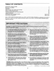
... IMPORTANT PRECAUTIONS BEFORE YOU BEGIN ASSEMBLY HOW TO USE THE HOME GYM SYSTEM WEIGHT RESISTANCE CHART TROUBLE-SHOOTING AND MAINTENANCE CABLE DIAGRAMS ORDERING REPLACEMENT PARTS FULL 90 DAY WARRANTY 2 3 4 22 24 25 26 Back Cover Back Cover Note: A PART IDENTIFICATION CHART and a PART LIST/EXPLODED DRAWING are exercising, stop immediately and begin cooling down. Your hand could cause the home gym system to the center of the pulleys. If the cables bind while you feel pain...
... IMPORTANT PRECAUTIONS BEFORE YOU BEGIN ASSEMBLY HOW TO USE THE HOME GYM SYSTEM WEIGHT RESISTANCE CHART TROUBLE-SHOOTING AND MAINTENANCE CABLE DIAGRAMS ORDERING REPLACEMENT PARTS FULL 90 DAY WARRANTY 2 3 4 22 24 25 26 Back Cover Back Cover Note: A PART IDENTIFICATION CHART and a PART LIST/EXPLODED DRAWING are exercising, stop immediately and begin cooling down. Your hand could cause the home gym system to the center of the pulleys. If the cables bind while you feel pain...
English Manual
Page 3
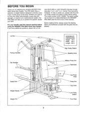
... attached to achieve the specific results you have additional questions, please call our toll- High Pulley Station Butterfly Arms Military Press Arm Backrests Leg Press Plate Press Arm Leg Lever Low Pulley Station Foot Plate 3 BEFORE YOU BEGIN Thank you , please note the product model number and serial number before using the WEIDER® PRO 9645 Home Gym System. Central Time (excluding holidays). Lat Bar Pull-up Handles Dip Handles Assist Arm Weight Stacks Weight Pin O O 0 0 0 00 O° 0 ASSEMBLED DIMENSIONS...
... attached to achieve the specific results you have additional questions, please call our toll- High Pulley Station Butterfly Arms Military Press Arm Backrests Leg Press Plate Press Arm Leg Lever Low Pulley Station Foot Plate 3 BEFORE YOU BEGIN Thank you , please note the product model number and serial number before using the WEIDER® PRO 9645 Home Gym System. Central Time (excluding holidays). Lat Bar Pull-up Handles Dip Handles Assist Arm Weight Stacks Weight Pin O O 0 0 0 00 O° 0 ASSEMBLED DIMENSIONS...
English Manual
Page 4
..." x 2 3/4" Bolts (11), two 5/16" Flat Washers (8), and two 5/16" Nylon Locknuts (3). Note: Some small parts may have read the following tools: A socket set, a set of the PRO 9645 in the box above. do otherwise. Locate and open -end or closed-end wrenches, or a set of this manual. Press a 2" Square Inner Cap (27) into four stages: 1) frame assembly, 2) arm assembly, 3) cable and pulley assembly, and 4) seat and backrest assembly. Do...
..." x 2 3/4" Bolts (11), two 5/16" Flat Washers (8), and two 5/16" Nylon Locknuts (3). Note: Some small parts may have read the following tools: A socket set, a set of the PRO 9645 in the box above. do otherwise. Locate and open -end or closed-end wrenches, or a set of this manual. Press a 2" Square Inner Cap (27) into four stages: 1) frame assembly, 2) arm assembly, 3) cable and pulley assembly, and 4) seat and backrest assembly. Do...

English Manual
Page 5
... Carriage Bolts. Press two 2" Square Inner Caps (27) into the Assist Upright (74). Press a 2" Square Inner Cap into the Leg Press Upright (56). Slide the Assist Upright (74) and the Leg Press Upright (56) onto the indicated 5/16" x 2 1/2" Carriage Bolts (1) in the Base (4). 3 Hand-tighten a 5/16" Nylon Locknut (3) onto each Carriage Bolt. Attach the Rubber Bumper (91) to the Leg Press Upright (56) with the #8 x 1/2" Self-tapping Screw (87...
... Carriage Bolts. Press two 2" Square Inner Caps (27) into the Assist Upright (74). Press a 2" Square Inner Cap into the Leg Press Upright (56). Slide the Assist Upright (74) and the Leg Press Upright (56) onto the indicated 5/16" x 2 1/2" Carriage Bolts (1) in the Base (4). 3 Hand-tighten a 5/16" Nylon Locknut (3) onto each Carriage Bolt. Attach the Rubber Bumper (91) to the Leg Press Upright (56) with the #8 x 1/2" Self-tapping Screw (87...
English Manual
Page 6
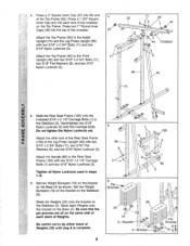
..." Nylon Locknuts (3). Attach the other end of the Rear Seat Frame (100) to the Leg Press Upright (56) with two 5/16" x 2 3/4" Bolts (11), two 5/16" Flat Washers (8), and two 5/16" Nylon Locknuts (3). 55 11 49 8 44 3 44 Crossbar 3 56 42 ---74 LU 5 Slide the Rear Seat Frame (100) onto the indicated 5/16" x 2 1/2" Carriage Bolts (1) in steps 1-5. Stack eight Weights onto the bracket...
..." Nylon Locknuts (3). Attach the other end of the Rear Seat Frame (100) to the Leg Press Upright (56) with two 5/16" x 2 3/4" Bolts (11), two 5/16" Flat Washers (8), and two 5/16" Nylon Locknuts (3). 55 11 49 8 44 3 44 Crossbar 3 56 42 ---74 LU 5 Slide the Rear Seat Frame (100) onto the indicated 5/16" x 2 1/2" Carriage Bolts (1) in steps 1-5. Stack eight Weights onto the bracket...
English Manual
Page 8
.... Attach the Press Frame (17) to the Base (4) with the Bolt and a 3/8" Nylon Locknut (21). 4 Tube 8 95 96 21 27 27 Welded Tube 97 67-Lubricate 5 27 98 0 0 0 0 17 Pulleys must be able to the Top Frame (55) in the Base. The Leg Press Arm must be a tight fit. Do not overtighten the Nylon Locknut. Locate and open the parts bag labeled "ARM ASSEMBLY...
.... Attach the Press Frame (17) to the Base (4) with the Bolt and a 3/8" Nylon Locknut (21). 4 Tube 8 95 96 21 27 27 Welded Tube 97 67-Lubricate 5 27 98 0 0 0 0 17 Pulleys must be able to the Top Frame (55) in the Base. The Leg Press Arm must be a tight fit. Do not overtighten the Nylon Locknut. Locate and open the parts bag labeled "ARM ASSEMBLY...
English Manual
Page 9
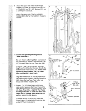
.... 46 49 -46 17 13. Attach a "V"-Pulley (50) and a Long Cable Trap (31) to identify the Right Arm. Be sure that the upper end of each Arm with two 5/16" x 2 1/2" Bolts (22) and two 5/16" Nylon Locknuts (3). 22 Assemble the other Press Arm (46) in the inset drawing. refer to step 13 to the Left Arm (47) in the same manner...
.... 46 49 -46 17 13. Attach a "V"-Pulley (50) and a Long Cable Trap (31) to identify the Right Arm. Be sure that the upper end of each Arm with two 5/16" x 2 1/2" Bolts (22) and two 5/16" Nylon Locknuts (3). 22 Assemble the other Press Arm (46) in the inset drawing. refer to step 13 to the Left Arm (47) in the same manner...
English Manual
Page 11
... manual to the Top Frame (55) with im soapy water. IMPORTANT: While assembling the cables, do not overtighten the bolts and nuts attaching the pulleys. The approximate length of the Pulley and that the end of this section, fully unwind the four Cables. Locate and open the parts bags labeled "CABLE ASSEMBLY" and "PULLEYS." 17. Press a1 1/4" Round Inner Cap (109) into the Left Dip Arm...
... manual to the Top Frame (55) with im soapy water. IMPORTANT: While assembling the cables, do not overtighten the bolts and nuts attaching the pulleys. The approximate length of the Pulley and that the end of this section, fully unwind the four Cables. Locate and open the parts bags labeled "CABLE ASSEMBLY" and "PULLEYS." 17. Press a1 1/4" Round Inner Cap (109) into the Left Dip Arm...
English Manual
Page 13
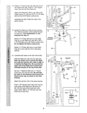
... a 3/8" Nylon Locknut (21). Do not remove the Bolt. Attach a 3 1/2" Pulley (15) and a Cable Trap (66) to complete the assembly of the Pulley and that the Cable and Pulley move smoothly. 24 58 66 15 0 21 v. Note: This assembly step shows how to the upper hole in the groove of several pre- 26 attached parts. The Bolt has been shown removed for shipping purposes. Reattach the 3 1/2" Low...
... a 3/8" Nylon Locknut (21). Do not remove the Bolt. Attach a 3 1/2" Pulley (15) and a Cable Trap (66) to complete the assembly of the Pulley and that the Cable and Pulley move smoothly. 24 58 66 15 0 21 v. Note: This assembly step shows how to the upper hole in the groove of several pre- 26 attached parts. The Bolt has been shown removed for shipping purposes. Reattach the 3 1/2" Low...

English Manual
Page 14
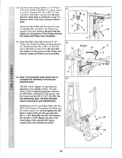
.... Tighten the 3/8" Nylon Locknut (21) and the 3/8" x 3 1/2" Bolt (not shown). 51 . 23 /® 15 ® 21 66 17 30. Route the Low Cable (23) around the 3 1/2" Pulley (15) attached to the upper hole in the 29 Press Frame (17). Locate the Low Cable (23). Route the Low Cable (23) around the 3 1/2" Pulley (15) attached to the upper hole in the 30 Front Upright (42...
.... Tighten the 3/8" Nylon Locknut (21) and the 3/8" x 3 1/2" Bolt (not shown). 51 . 23 /® 15 ® 21 66 17 30. Route the Low Cable (23) around the 3 1/2" Pulley (15) attached to the upper hole in the 29 Press Frame (17). Locate the Low Cable (23). Route the Low Cable (23) around the 3 1/2" Pulley (15) attached to the upper hole in the 30 Front Upright (42...
English Manual
Page 18
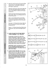
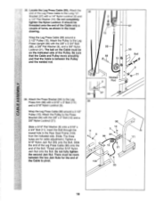
... side of the Leg Press Cable to the Leg Press Arm (96) with a 1/4" Nylon Locknut (2) and a 1/4" Flat Washer (10). Do not fully tighten the second Jam Nut. Wrap the Leg Press Cable (99) around a 3 1/2" Pulley (15). Attach the Press Bracket (94) to the Long "U"- 38 Bracket (57) with a 5/16" x 3" Bolt (111) and a 5/16" Nylon Locknut (3). Wrap the Leg Press Cable (99) around a 3 1/2" Pulley (15). Locate the Leg Press Cable (99). Attach the end...
... side of the Leg Press Cable to the Leg Press Arm (96) with a 1/4" Nylon Locknut (2) and a 1/4" Flat Washer (10). Do not fully tighten the second Jam Nut. Wrap the Leg Press Cable (99) around a 3 1/2" Pulley (15). Attach the Press Bracket (94) to the Long "U"- 38 Bracket (57) with a 5/16" x 3" Bolt (111) and a 5/16" Nylon Locknut (3). Wrap the Leg Press Cable (99) around a 3 1/2" Pulley (15). Locate the Leg Press Cable (99). Attach the end...

English Manual
Page 19
Locate and open the parts bag labeled "SEAT ASSEMBLY." 40 Insert a 1/4" x 2 1/2" Carriage Bolt (92) through the indicated hole in a Seat Plate (37). Attach the Seat Plate to the Rear Seat Frame (100) with a 1/4" x 2 1/2" Screw (43) and a 1/4" Flat Washer (10). 85 56 0 43 0 37 92 18 10 2 41. Attach the other end of the Rear Backrest (85) to the Leg Press Upright with two 1/4" x 1/2" Screws 41 (18). 40. Insert the...
Locate and open the parts bag labeled "SEAT ASSEMBLY." 40 Insert a 1/4" x 2 1/2" Carriage Bolt (92) through the indicated hole in a Seat Plate (37). Attach the Seat Plate to the Rear Seat Frame (100) with a 1/4" x 2 1/2" Screw (43) and a 1/4" Flat Washer (10). 85 56 0 43 0 37 92 18 10 2 41. Attach the other end of the Rear Backrest (85) to the Leg Press Upright with two 1/4" x 1/2" Screws 41 (18). 40. Insert the...

English Manual
Page 20
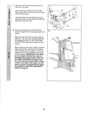
...;° -32 36 81 10 2 45 /`` 36 Lubricate-33 - U) 45. "tip 29 8 35 t. - 3 32 :,..;,- 46 4 2 40 4 , 36 , / Pin 20 Tighten a 1/4" Nylon Locknut (2) with a 1/4" Flat Washer (10) onto the Carriage Bolt. Lubricate the 5/16" x 2 1/4" Bolt (33). Press a 1 1/2" Square Inner Cap (32) into the Front Seat Frame (36). Insert the 5/16" x 2" Eyebolt (35) into the Leg Lever (29) from the direction shown.
...;° -32 36 81 10 2 45 /`` 36 Lubricate-33 - U) 45. "tip 29 8 35 t. - 3 32 :,..;,- 46 4 2 40 4 , 36 , / Pin 20 Tighten a 1/4" Nylon Locknut (2) with a 1/4" Flat Washer (10) onto the Carriage Bolt. Lubricate the 5/16" x 2 1/4" Bolt (33). Press a 1 1/2" Square Inner Cap (32) into the Front Seat Frame (36). Insert the 5/16" x 2" Eyebolt (35) into the Leg Lever (29) from the direction shown.
English Manual
Page 21
... using the home gym system, pull each end of this manual for proper cable routing. If there is used. The use of the remaining parts will need to remove it to be sure that all parts have been properly tightened. If one of the cables does not move smoothly over the pulleys. Remove the backing from the PRO 9645 decal and apply it by tightening the cables. Make sure that the cables move...
... using the home gym system, pull each end of this manual for proper cable routing. If there is used. The use of the remaining parts will need to remove it to be sure that all parts have been properly tightened. If one of the cables does not move smoothly over the pulleys. Remove the backing from the PRO 9645 decal and apply it by tightening the cables. Make sure that the cables move...
English Manual
Page 22
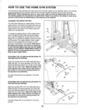
... STRAP TO THE LOW PULLEY STATION Attach the Lat Bar (54) to the Low Cable (23) with a Cable Clip (53). Note: Due to the cables and pulleys, the amount of resistance at each part of 12.5 pounds. Adjust the length of resis- HOW TO USE THE HOME GYM SYSTEM The instructions below describe how each weight station. 25 26 ATTACHING THE LAT BAR OR NYLON STRAP TO THE HIGH PULLEY STATION Attach the Lat Bar...
... STRAP TO THE LOW PULLEY STATION Attach the Lat Bar (54) to the Low Cable (23) with a Cable Clip (53). Note: Due to the cables and pulleys, the amount of resistance at each part of 12.5 pounds. Adjust the length of resis- HOW TO USE THE HOME GYM SYSTEM The instructions below describe how each weight station. 25 26 ATTACHING THE LAT BAR OR NYLON STRAP TO THE HIGH PULLEY STATION Attach the Lat Bar...

English Manual
Page 23
... PULLEY STATION To use the Leg Lever (29), the seat must be removed. Align the welded tubes on the Leg Press Plate (95) with the 5/16" x 2 3/4" Carriage Bolt (14) and the Seat Knob (40). Attach the Front Seat Frame to the Front Upright with the desired set the bracket on the Front Seat Frame (36) onto the indicated pins on Leg Press Plate and the holes in the Leg Press Arm...
... PULLEY STATION To use the Leg Lever (29), the seat must be removed. Align the welded tubes on the Leg Press Plate (95) with the 5/16" x 2 3/4" Carriage Bolt (14) and the Seat Knob (40). Attach the Front Seat Frame to the Front Upright with the desired set the bracket on the Front Seat Frame (36) onto the indicated pins on Leg Press Plate and the holes in the Leg Press Arm...
English Manual
Page 24
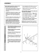
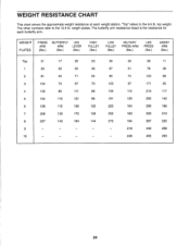
WEIGHT PLATES PRESS ARM (lbs.) BUTTERFLY LEG ARM LEVER (lbs.) (lbs.) HIGH PULLEY (lbs.) LOW PULLEY (lbs.) MILITARY PRESS ARM (lbs.) LEG PRESS (lbs.) ASSIST ARM (lbs.) Top 31 17 25 23 36 30 36 11 1 59 35 50 36 67 ... 273 194 387 232 9 - - - 218 440 256 10 - - - 246 455 293 24 The other numbers refer to the 6.5 lb. The butterfly arm resistance listed is the resistance for each weight station. weight plates. "Top" refers to the 12.5 lb. top weight. WEIGHT RESISTANCE CHART This chart shows the approximate weight resistance at each butterfly...
WEIGHT PLATES PRESS ARM (lbs.) BUTTERFLY LEG ARM LEVER (lbs.) (lbs.) HIGH PULLEY (lbs.) LOW PULLEY (lbs.) MILITARY PRESS ARM (lbs.) LEG PRESS (lbs.) ASSIST ARM (lbs.) Top 31 17 25 23 36 30 36 11 1 59 35 50 36 67 ... 273 194 387 232 9 - - - 218 440 256 10 - - - 246 455 293 24 The other numbers refer to the 6.5 lb. The butterfly arm resistance listed is the resistance for each weight station. weight plates. "Top" refers to the 12.5 lb. top weight. WEIGHT RESISTANCE CHART This chart shows the approximate weight resistance at each butterfly...
English Manual
Page 25
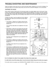
... cleaned using the Leg Press Arm (96), then the end of this manual. 25 Tighten the 1/4" Nylon Locknut (2) that the Cable Trap is in the cables before resistance is felt when using the rear weight stack, both 5/16" Nylon Jam Nuts (93) from the Rear Seat Frame. Reattach the Pulley and Cable Trap. Remove the cable and re-install it. Move the 3 1/2" Pulley (15) to the Long "U"Bracket (57). The home gym system...
... cleaned using the Leg Press Arm (96), then the end of this manual. 25 Tighten the 1/4" Nylon Locknut (2) that the Cable Trap is in the cables before resistance is felt when using the rear weight stack, both 5/16" Nylon Jam Nuts (93) from the Rear Seat Frame. Reattach the Pulley and Cable Trap. Remove the cable and re-install it. Move the 3 1/2" Pulley (15) to the Long "U"Bracket (57). The home gym system...
English Manual
Page 28
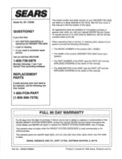
... (excluding holidays) REPLACEMENT PARTS If parts become worn and need to schedule repair service call the following information: • The MODEL NUMBER of the product (831.159380). • The NAME of the product (WEIDER® PRO 9645 Home Gym System). • The PART NUMBER of the PART (see the PART LIST and the EXPLODED DRAWING at the center of this manual). • The DESCRIPTION of the PART (see the PART LIST and the...
... (excluding holidays) REPLACEMENT PARTS If parts become worn and need to schedule repair service call the following information: • The MODEL NUMBER of the product (831.159380). • The NAME of the product (WEIDER® PRO 9645 Home Gym System). • The PART NUMBER of the PART (see the PART LIST and the EXPLODED DRAWING at the center of this manual). • The DESCRIPTION of the PART (see the PART LIST and the...


