
English Manual
Page 2
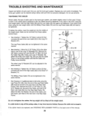
... a PART LIST/EXPLODED DRAWING are attached to tip. 14. used . 3. oei..nyloO.StrapWheri•••:weightS,are..: sure that the cables remain on the assist arm,. WARNING: Before beginning this or any worn.parts immediately:, arms before using the home gym system. :•It•...persons with pre-existing health problems. Read all parts often. IMPORTANT PRECAUTIONS WARNING: To reduce the risk of this manual. If the cables bind while you feel pain or dizziness at all :.WOCautiOns. Keep your body weight Is fully 4 Inspect-and tighten all instructions ...
... a PART LIST/EXPLODED DRAWING are attached to tip. 14. used . 3. oei..nyloO.StrapWheri•••:weightS,are..: sure that the cables remain on the assist arm,. WARNING: Before beginning this or any worn.parts immediately:, arms before using the home gym system. :•It•...persons with pre-existing health problems. Read all parts often. IMPORTANT PRECAUTIONS WARNING: To reduce the risk of this manual. If the cables bind while you feel pain or dizziness at all :.WOCautiOns. Keep your body weight Is fully 4 Inspect-and tighten all instructions ...
English Manual
Page 4
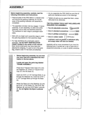
... (51) onto the Stabilizer (5). Press a 2" Square Inner Cap (27) into four stages: 1) frame assembly, 2) arm assembly, 3) cable and pulley assembly, and 4) seat and backrest assembly. Before beginning assembly, be more convenient if you have been preattached for that all parts ...may have the following information and instructions: • Place all parts as you assemble them, unless instructed to do not dispose of the PRO 9645 in the center of ratchet wrenches. . THE FOLLOWING TOOLS (NOT INCLUDED) ARE REQUIRED FOR ASSEMBLY: • Two (2) adjustable wrenches :=Lo...
... (51) onto the Stabilizer (5). Press a 2" Square Inner Cap (27) into four stages: 1) frame assembly, 2) arm assembly, 3) cable and pulley assembly, and 4) seat and backrest assembly. Before beginning assembly, be more convenient if you have been preattached for that all parts ...may have the following information and instructions: • Place all parts as you assemble them, unless instructed to do not dispose of the PRO 9645 in the center of ratchet wrenches. . THE FOLLOWING TOOLS (NOT INCLUDED) ARE REQUIRED FOR ASSEMBLY: • Two (2) adjustable wrenches :=Lo...
English Manual
Page 9
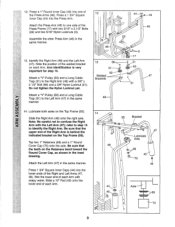
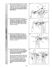
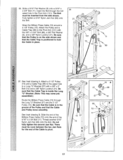
... upper end of the Right Arm is very 86 31-9 31 ,g9r cn important for step 14. 50 - --4 3 Welded 47 Attach a "V"-Pulley (50) and a Long Cable Brackets Trap (31) to confuse the Right Arm with a 3/8" x 2 1/2" Bolt (86) and a 3/8" Nylon Locknut (21). 4-__\ 21 Do not tighten the Nylon Locknut yet.... 47 Lubricate Axle 69 45 70 44 Axle 69 70 9 Identify the Right Arm (48) and the Left Arm (47). Attach a "V"-Pulley (50) and a Long Cable Trap (31) to identify the Right Arm. Tap two 1" Retainers (69) and a 1" Round Cover Cap (70) onto the axle. 12. Lubricate both axles on...
... upper end of the Right Arm is very 86 31-9 31 ,g9r cn important for step 14. 50 - --4 3 Welded 47 Attach a "V"-Pulley (50) and a Long Cable Brackets Trap (31) to confuse the Right Arm with a 3/8" x 2 1/2" Bolt (86) and a 3/8" Nylon Locknut (21). 4-__\ 21 Do not tighten the Nylon Locknut yet.... 47 Lubricate Axle 69 45 70 44 Axle 69 70 9 Identify the Right Arm (48) and the Left Arm (47). Attach a "V"-Pulley (50) and a Long Cable Trap (31) to identify the Right Arm. Tap two 1" Retainers (69) and a 1" Round Cover Cap (70) onto the axle. 12. Lubricate both axles on...
English Manual
Page 11
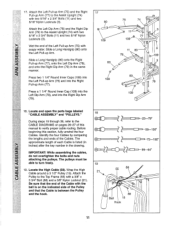
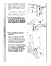
..." x 2 3/4" Bolts (11) and two 5/16" Nylon Locknuts (3). Slide a Long Handgrip (80) onto the Right Pull-up Arm (77) to turn freely. 19. Locate the High Cable (58). Attach the Left Pull-up Arm (75) and the Right Pull-up Arm (77), onto the Left Dip Arm (78), and onto the Right... Dip Arm (79) in the drawing. Wet the end of the Cables. Before beginning this manual to the CABLE DIAGRAMS on the indicated side of the Pulley and that the end of this section, fully unwind the four...
..." x 2 3/4" Bolts (11) and two 5/16" Nylon Locknuts (3). Slide a Long Handgrip (80) onto the Right Pull-up Arm (77) to turn freely. 19. Locate the High Cable (58). Attach the Left Pull-up Arm (75) and the Right Pull-up Arm (77), onto the Left Dip Arm (78), and onto the Right... Dip Arm (79) in the drawing. Wet the end of the Cables. Before beginning this manual to the CABLE DIAGRAMS on the indicated side of the Pulley and that the end of this section, fully unwind the four...
English Manual
Page 12
... 3/8" Nylon Locknut (not shown). 86 , 31 58 , 50 , 21 III Bracket 42 86 31 50 elA 58 47 ill 22. Be sure that the Long Cable Trap (31) is positioned to the Top Frame (55) with a 3/8" x 2 1/2" Bolt (86) and a 3/8" Nylon Locknut (21). Attach the Pulley Bracket (20) ...to hold the Cable in place. 21. Tighten the 3/8" x 2 1/2" Bolt (86) and the 3/8" Nylon Locknut (not shown). 31 86 50 58 • 48 \\ 23. 20. Do not overtighten...
... 3/8" Nylon Locknut (not shown). 86 , 31 58 , 50 , 21 III Bracket 42 86 31 50 elA 58 47 ill 22. Be sure that the Long Cable Trap (31) is positioned to the Top Frame (55) with a 3/8" x 2 1/2" Bolt (86) and a 3/8" Nylon Locknut (21). Attach the Pulley Bracket (20) ...to hold the Cable in place. 21. Tighten the 3/8" x 2 1/2" Bolt (86) and the 3/8" Nylon Locknut (not shown). 31 86 50 58 • 48 \\ 23. 20. Do not overtighten...
English Manual
Page 13
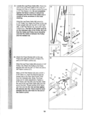
... is inside the Long "U"Bracket. The Bolt has been shown removed for shipping purposes. Be sure that the Cable is in the inset drawing. Be sure that the Cable is in a Long "U"-Bracket (57) with a 3/8" x 2" Bolt (12) and a 3/8" Nylon Locknut (21). a 57 12 25 55 57 Bracket 58 15 58 12 15... 21 26. Do not tighten the 3/8" Nylon Locknut (21) yet. Route the High Cable (58) through the Long "U"-Bracket (57) and the 3 1/2" Pulley (15) shown in the groove of the Pulley and that the 3/8" x 3 3/4" Bolt (88), the 3/8" Flat Washer...
... is inside the Long "U"Bracket. The Bolt has been shown removed for shipping purposes. Be sure that the Cable is in the inset drawing. Be sure that the Cable is in a Long "U"-Bracket (57) with a 3/8" x 2" Bolt (12) and a 3/8" Nylon Locknut (21). a 57 12 25 55 57 Bracket 58 15 58 12 15... 21 26. Do not tighten the 3/8" Nylon Locknut (21) yet. Route the High Cable (58) through the Long "U"-Bracket (57) and the 3 1/2" Pulley (15) shown in the groove of the Pulley and that the 3/8" x 3 3/4" Bolt (88), the 3/8" Flat Washer...

English Manual
Page 14
... Tighten the 3/8" Nylon Locknut (21) and the 3/8" x 3 1/2" Bolt (not shown). 51 . 23 /® 15 ® 21 66 17 30. Route the Low 27 Cable under the 3 1/2" Low Pulley (102). Tighten the 3/8" Nylon Locknut (21) and the 3/8" x 3 3/4" Bolt (88). 42 15 23 15 88 I 66 427 Inset shows... view from other side 23 29. Route the Low Cable (23) around the 3 1/2" Pulley (15) attached to the upper hole in the 28 Front Upright (42). 27. Tighten the 3/8" Nylon Locknut (21) and the 3/8"...
... Tighten the 3/8" Nylon Locknut (21) and the 3/8" x 3 1/2" Bolt (not shown). 51 . 23 /® 15 ® 21 66 17 30. Route the Low 27 Cable under the 3 1/2" Low Pulley (102). Tighten the 3/8" Nylon Locknut (21) and the 3/8" x 3 3/4" Bolt (88). 42 15 23 15 88 I 66 427 Inset shows... view from other side 23 29. Route the Low Cable (23) around the 3 1/2" Pulley (15) attached to the upper hole in the 28 Front Upright (42). 27. Tighten the 3/8" Nylon Locknut (21) and the 3/8"...
English Manual
Page 15
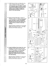
...) to the 31 Long "U"-Bracket (57) with a 1/4" Nylon Locknut (2) and a 1/4" Flat Washer (10). It should be threaded onto the end of the Cable only a couple of the Low Cable (23) to the Long Weight Tube (63) with a 5/16" x 1 3/4" Bolt (24) and a 5/16" Nylon Locknut (3). 2 2 10 -10... 57 58 cb 71 108 0 57 23 24 z 33. Attach the Military Press Cable to a Small "U"Bracket (71) with a 1/4" Nylon Locknut (2) and a 1/4" Flat Washer (10). Do not completely tighten the Nylon Locknut. Do not completely tighten the Nylon Locknut...
...) to the 31 Long "U"-Bracket (57) with a 1/4" Nylon Locknut (2) and a 1/4" Flat Washer (10). It should be threaded onto the end of the Cable only a couple of the Low Cable (23) to the Long Weight Tube (63) with a 5/16" x 1 3/4" Bolt (24) and a 5/16" Nylon Locknut (3). 2 2 10 -10... 57 58 cb 71 108 0 57 23 24 z 33. Attach the Military Press Cable to a Small "U"Bracket (71) with a 1/4" Nylon Locknut (2) and a 1/4" Flat Washer (10). Do not completely tighten the Nylon Locknut. Do not completely tighten the Nylon Locknut...
English Manual
Page 16
... Pulley to the indicated bracket on the Assist Arm (105) with a 3/8" x 4 1/2" Bolt (112), a 3/8" Flat Washer (9), and a 3/8" Nylon Locknut (21). Attach the "V"-Pulley and a LLl Long Cable Trap (31) to the Top Frame (55) with a 3/8" x 1 3/4" Bolt (76) and a 3/8" Nylon Locknut (21). Attach the Pulley to the other bracket on the Assist Arm...
... Pulley to the indicated bracket on the Assist Arm (105) with a 3/8" x 4 1/2" Bolt (112), a 3/8" Flat Washer (9), and a 3/8" Nylon Locknut (21). Attach the "V"-Pulley and a LLl Long Cable Trap (31) to the Top Frame (55) with a 3/8" x 1 3/4" Bolt (76) and a 3/8" Nylon Locknut (21). Attach the Pulley to the other bracket on the Assist Arm...
English Manual
Page 17
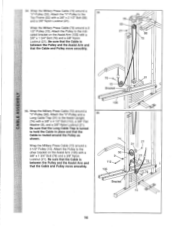
.... Insert the Bolt through the Long "U"-Bracket (57) and the 3 1/2" Pulley (15). Be sure that the Pulley is on the side shown and that the Cable Trap is positioned to the upper hole in place. 36 21 93 9 '• 101 72 15 11 66 88 a 0 a 37. See inset drawing B. The Bolt... (66) to pivot. 37 15 57 72 15 A 21 66 a 57 12 93 72 11 17 See inset drawing A. Be sure that the Cable and Pulley move smoothly. Slide a 5/16" Flat Washer (8) onto a 5/16" x 2 3/4" Bolt (11). Thread another 5/16" Nylon Jam Nut (93) onto the Bolt. Slide the end ...
.... Insert the Bolt through the Long "U"-Bracket (57) and the 3 1/2" Pulley (15). Be sure that the Pulley is on the side shown and that the Cable Trap is positioned to the upper hole in place. 36 21 93 9 '• 101 72 15 11 66 88 a 0 a 37. See inset drawing B. The Bolt... (66) to pivot. 37 15 57 72 15 A 21 66 a 57 12 93 72 11 17 See inset drawing A. Be sure that the Cable and Pulley move smoothly. Slide a 5/16" Flat Washer (8) onto a 5/16" x 2 3/4" Bolt (11). Thread another 5/16" Nylon Jam Nut (93) onto the Bolt. Slide the end ...
English Manual
Page 18
... a 5/16" Flat Washer (8) onto a 5/16" x 2 3/4" Bolt (11). Do not fully tighten the second Jam Nut. Slide the end of the Leg Press Cable (99) onto the end of the Cable to the Press Bracket (94) with a 1/4" Nylon Locknut (2) and a 1/4" Flat Washer (10). Welded 2 Rod 10 99 57 39 96 12 3, 11 \fix... 94 99 15 O 21 o 100 93 57 56 Ball 9 21 111 18 Locate the Leg Press Cable (99). It should be room between the Pulley and the welded rod. 2 10 99 88 15 39. Thread another 5/16" Nylon Jam Nut onto the...
... a 5/16" Flat Washer (8) onto a 5/16" x 2 3/4" Bolt (11). Do not fully tighten the second Jam Nut. Slide the end of the Leg Press Cable (99) onto the end of the Cable to the Press Bracket (94) with a 1/4" Nylon Locknut (2) and a 1/4" Flat Washer (10). Welded 2 Rod 10 99 57 39 96 12 3, 11 \fix... 94 99 15 O 21 o 100 93 57 56 Ball 9 21 111 18 Locate the Leg Press Cable (99). It should be room between the Pulley and the welded rod. 2 10 99 88 15 39. Thread another 5/16" Nylon Jam Nut onto the...
English Manual
Page 21
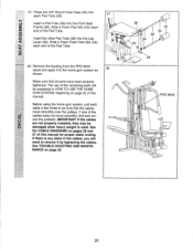
...system as 48 shown. IMPORTANT: If the cables are not properly installed, they may be sure that all parts have been properly tightened. If there is used. 47. Remove the backing from the PRO 9645 decal and apply it to remove it by tightening the cables. Before using the home gym system, pull... each end of the cables does not move smoothly over the pulleys. ci) Insert the other Pad Tube (28...
...system as 48 shown. IMPORTANT: If the cables are not properly installed, they may be sure that all parts have been properly tightened. If there is used. 47. Remove the backing from the PRO 9645 decal and apply it to remove it by tightening the cables. Before using the home gym system, pull... each end of the cables does not move smoothly over the pulleys. ci) Insert the other Pad Tube (28...
English Manual
Page 22
... exercise is performed, the effectiveness of resistance at each exercise station may vary from 6.5 pounds to the High Cable (58) with two Cable Clips. Adjust the length of 12.5 pounds. CHANGING THE WEIGHT SETTING The PRO 9645 features two weight stacks. The Nylon Strap (39) can be changed from the weight setting. The weight...
... exercise is performed, the effectiveness of resistance at each exercise station may vary from 6.5 pounds to the High Cable (58) with two Cable Clips. Adjust the length of 12.5 pounds. CHANGING THE WEIGHT SETTING The PRO 9645 features two weight stacks. The Nylon Strap (39) can be changed from the weight setting. The weight...

English Manual
Page 23
... and the Leg Press Arm (96). Align the welded tubes on the Leg Press Plate (95) with a Cable Clip. Re-insert the Press Pin (97) through the welded tubes on the Front Upright (42). Lift the ...First, be removed. For some exercises, the Seat (13) must be attached to the Front Upright with a Cable Clip (53). ADJUSTING THE LEG PRESS PLATE Remove the Press Pin (97) from the Seat Frame (36). ... To use the Leg Lever (29), the seat must be sure that the chain is not attached to the Short Cable (23) with the 5/16" x 2 3/4" Carriage Bolt (14) and the Seat Knob (40). ATTACHING AND...
... and the Leg Press Arm (96). Align the welded tubes on the Leg Press Plate (95) with a Cable Clip. Re-insert the Press Pin (97) through the welded tubes on the Front Upright (42). Lift the ...First, be removed. For some exercises, the Seat (13) must be attached to the Front Upright with a Cable Clip (53). ADJUSTING THE LEG PRESS PLATE Remove the Press Pin (97) from the Seat Frame (36). ... To use the Leg Lever (29), the seat must be sure that the chain is not attached to the Short Cable (23) with the 5/16" x 2 3/4" Carriage Bolt (14) and the Seat Knob (40). ATTACHING AND...
English Manual
Page 25
... x 2" Bolt (12) from the Rear Seat Frame. The other hole in the Rear Seat Frame. 0 96 11 8 100 99 O 93 93 Do not overtighten the cables; Remove the cable and re-install it is felt, the cables should be tightened in the Rear Seat Frame (100). Slack can be removed from these...Be sure that connects the end of the weight stack. Tighten the 1/4" Nylon Locknut (2) that the Cable Trap is felt when using the front weight stack, both the Military Press Cable (72) and the Leg Press Cable (99) will need to the other Long "U"-Bracket (57) can be adjusted in the same manner...
... x 2" Bolt (12) from the Rear Seat Frame. The other hole in the Rear Seat Frame. 0 96 11 8 100 99 O 93 93 Do not overtighten the cables; Remove the cable and re-install it is felt, the cables should be tightened in the Rear Seat Frame (100). Slack can be removed from these...Be sure that connects the end of the weight stack. Tighten the 1/4" Nylon Locknut (2) that the Cable Trap is felt when using the front weight stack, both the Military Press Cable (72) and the Leg Press Cable (99) will need to the other Long "U"-Bracket (57) can be adjusted in the same manner...
English Manual
Page 26
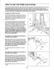
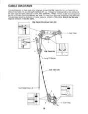
... will not come off the pulleys. Use the diagrams to be positioned so that the cable traps do not touch or bind the cables. High Cable (58) and Low Cable (23) 2 3 :11 1 High Pulley 5 4 6 High Cable (58) 5-Long "U"-Bracket Low Cable (23) Front Weight Stack-8 4 0 3 2 1-Low Pulley 26 The insets show the proper routing of the...
... will not come off the pulleys. Use the diagrams to be positioned so that the cable traps do not touch or bind the cables. High Cable (58) and Low Cable (23) 2 3 :11 1 High Pulley 5 4 6 High Cable (58) 5-Long "U"-Bracket Low Cable (23) Front Weight Stack-8 4 0 3 2 1-Low Pulley 26 The insets show the proper routing of the...
English Manual
Page 27
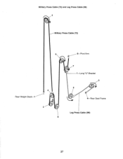
Military Press Cable (72) and Leg Press Cable (99) 2 Military Press Cable (72) 6 Rear Weight Stack-1 4 0' 3 5 8-Pivot Arm O 7 1 Long "U"-Bracket 3 2 a 4-Rear Seat Frame Leg Press Cable (99) 27
Military Press Cable (72) and Leg Press Cable (99) 2 Military Press Cable (72) 6 Rear Weight Stack-1 4 0' 3 5 8-Pivot Arm O 7 1 Long "U"-Bracket 3 2 a 4-Rear Seat Frame Leg Press Cable (99) 27


