
English Manual
Page 2
TABLE OF CONTENTS IMPORTANT PRECAUTIONS BEFORE YOU BEGIN ASSEMBLY HOW TO USE THE HOME GYM SYSTEM WEIGHT RESISTANCE CHART TROUBLE-SHOOTING AND MAINTENANCE CABLE DIAGRAMS ORDERING REPLACEMENT PARTS FULL 90 DAY WARRANTY 2 3 4 22 24 ...-and tighten all times. Your hand could cause the home gym system to the center of serious injury, read the following important.precautions before beginning assembly. Always disconnect the lat bar from moving parts. Remove the PART IDENTIFICATION CHART and the PART LIST/EXPLODED DRAWING before using . away.f.rorn the: home...
TABLE OF CONTENTS IMPORTANT PRECAUTIONS BEFORE YOU BEGIN ASSEMBLY HOW TO USE THE HOME GYM SYSTEM WEIGHT RESISTANCE CHART TROUBLE-SHOOTING AND MAINTENANCE CABLE DIAGRAMS ORDERING REPLACEMENT PARTS FULL 90 DAY WARRANTY 2 3 4 22 24 ...-and tighten all times. Your hand could cause the home gym system to the center of serious injury, read the following important.precautions before beginning assembly. Always disconnect the lat bar from moving parts. Remove the PART IDENTIFICATION CHART and the PART LIST/EXPLODED DRAWING before using . away.f.rorn the: home...
English Manual
Page 3
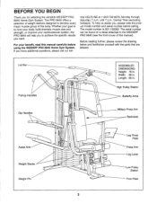
If you for selecting the versatile WEIDER® PRO 9645 Home Gym System. To help you to the WEIDER® PRO 9645 (see the front cover of the body. Lat Bar Pull-up Handles Dip Handles Assist Arm Weight Stacks Weight Pin O O 0 0 0 00 O° 0 ASSEMBLED DIMENSIONS: Height: 78 in . free HELPLINE at 1-800-736-6879, Monday through Saturday...
If you for selecting the versatile WEIDER® PRO 9645 Home Gym System. To help you to the WEIDER® PRO 9645 (see the front cover of the body. Lat Bar Pull-up Handles Dip Handles Assist Arm Weight Stacks Weight Pin O O 0 0 0 00 O° 0 ASSEMBLED DIMENSIONS: Height: 78 in . free HELPLINE at 1-800-736-6879, Monday through Saturday...
English Manual
Page 4
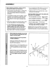
... 5/16" x 2 3/4" Bolts (11), two 5/16" Flat Washers (8), and two 5/16" Nylon Locknuts (3). Assembly will also be more convenient if you assemble the PRO 9645 be sure that all parts are oriented as shown in the drawings. • Tighten all parts of the PRO 9645 in a cleared area and remove the packing materials; co Insert six 5/16...
... 5/16" x 2 3/4" Bolts (11), two 5/16" Flat Washers (8), and two 5/16" Nylon Locknuts (3). Assembly will also be more convenient if you assemble the PRO 9645 be sure that all parts are oriented as shown in the drawings. • Tighten all parts of the PRO 9645 in a cleared area and remove the packing materials; co Insert six 5/16...
English Manual
Page 8
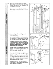
... 27 27 Welded Tube 97 67-Lubricate 5 27 98 0 0 0 0 17 Pulleys must be able to pivot freely. Locate and open the parts bag labeled "ARM ASSEMBLY." 10 Be sure there is a Bushing (98) in the same manner. 9 61 3 61 60 1O. Lubricate a 3/8" x 3 1/4" Bolt (67). The Leg Press Arm must be a tight...
... 27 27 Welded Tube 97 67-Lubricate 5 27 98 0 0 0 0 17 Pulleys must be able to pivot freely. Locate and open the parts bag labeled "ARM ASSEMBLY." 10 Be sure there is a Bushing (98) in the same manner. 9 61 3 61 60 1O. Lubricate a 3/8" x 3 1/4" Bolt (67). The Leg Press Arm must be a tight...
English Manual
Page 9
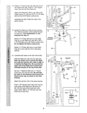
...) into the Press Arm. Attach the Press Arm (46) to confuse the Right Arm with two 5/16" x 2 1/2" Bolts (22) and two 5/16" Nylon Locknuts (3). 22 Assemble the other Press Arm (46) in the same 48 manner. (i ) 14. Slide a 10" Pad (45) onto the lower end of the welded bracket 13 on...
...) into the Press Arm. Attach the Press Arm (46) to confuse the Right Arm with two 5/16" x 2 1/2" Bolts (22) and two 5/16" Nylon Locknuts (3). 22 Assemble the other Press Arm (46) in the same 48 manner. (i ) 14. Slide a 10" Pad (45) onto the lower end of the welded bracket 13 on...
English Manual
Page 11
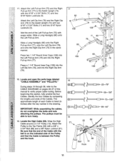
... Inner Cap (109) into the Left Dip Arm (78), and into the Right Pull-up Arm (77) to verify proper cable routing. IMPORTANT: While assembling the cables, do not overtighten the bolts and nuts attaching the pulleys. Locate the High Cable (58). Locate and open the parts bags labeled "CABLE... ASSEMBLY" and "PULLEYS." Slide a Long Handgrip (80) onto 2 the Left Pull-up Arm (75) with im soapy water. Identify the four Cables by comparing ...
... Inner Cap (109) into the Left Dip Arm (78), and into the Right Pull-up Arm (77) to verify proper cable routing. IMPORTANT: While assembling the cables, do not overtighten the bolts and nuts attaching the pulleys. Locate the High Cable (58). Locate and open the parts bags labeled "CABLE... ASSEMBLY" and "PULLEYS." Slide a Long Handgrip (80) onto 2 the Left Pull-up Arm (75) with im soapy water. Identify the four Cables by comparing ...
English Manual
Page 13
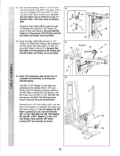
...part identification. Do not remove the Bolt. 24. See the inset drawing. Attach a 3 1/2" Pulley (15) and a Cable Trap (66) to complete the assembly of the Pulley and that the Cable and Pulley move smoothly. 25. Wrap the High Cable (58) around a 3 1/2" Pulley (15). Be sure that the...57) with a 3/8" x 2" Bolt (12) and a 3/8" Nylon Locknut (21). Be sure that the Cable is in the inset drawing. Note: This may come pre-assembled. Remove the 3/8" Nylon Locknut (21), the Spacer, and the Pulley from the 3/8" x 3 3/4" Bolt (88). Be sure that the Cable is inside the Long "U"Bracket....
...part identification. Do not remove the Bolt. 24. See the inset drawing. Attach a 3 1/2" Pulley (15) and a Cable Trap (66) to complete the assembly of the Pulley and that the Cable and Pulley move smoothly. 25. Wrap the High Cable (58) around a 3 1/2" Pulley (15). Be sure that the...57) with a 3/8" x 2" Bolt (12) and a 3/8" Nylon Locknut (21). Be sure that the Cable is in the inset drawing. Note: This may come pre-assembled. Remove the 3/8" Nylon Locknut (21), the Spacer, and the Pulley from the 3/8" x 3 3/4" Bolt (88). Be sure that the Cable is inside the Long "U"Bracket....

English Manual
Page 19
... Washers (10) and four 1/4" x 2 1/2" Screws (43). 42 104 110 105 *-10 Pc--43 10 43 19 18 0 Locate and open the parts bag labeled "SEAT ASSEMBLY." 40 Insert a 1/4" x 2 1/2" Carriage Bolt (92) through the indicated hole in a Seat Plate (37). Attach the other end of a Seat (13) to the Rear Backrest (85...
... Washers (10) and four 1/4" x 2 1/2" Screws (43). 42 104 110 105 *-10 Pc--43 10 43 19 18 0 Locate and open the parts bag labeled "SEAT ASSEMBLY." 40 Insert a 1/4" x 2 1/2" Carriage Bolt (92) through the indicated hole in a Seat Plate (37). Attach the other end of a Seat (13) to the Rear Backrest (85...
English Manual
Page 26
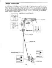
If the cables have been assembled correctly. High Cable (58) and Low Cable (23) 2 3 :11 1 High Pulley 5 4 6 High Cable (58) 5-Long "U"-Bracket Low Cable (23) Front Weight Stack-8 4 0 3 2 1-Low Pulley 26 ...
If the cables have been assembled correctly. High Cable (58) and Low Cable (23) 2 3 :11 1 High Pulley 5 4 6 High Cable (58) 5-Long "U"-Bracket Low Cable (23) Front Weight Stack-8 4 0 3 2 1-Low Pulley 26 ...
English Manual
Page 28
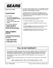
...of this manual). • The DESCRIPTION of the PART (see the PART LIST and the EXPLODED DRAWING at the left. When requesting help assembling or operating the WEIDER® PRO 9645 • a part is used commercially orfor rental purposes. SEARS, ROEBUCK AND CO., DEPT. 817WA, HOFFMAN ESTATES, IL 60179 Part No... 90 DAY WARRANTY For 90 days from state to the frame. This warranty gives you specific legal rights, and you visit your WEIDER® PRO 9645 are available for immediate purchase or special order when you may also have other rights which vary from the date of purchase, if...
...of this manual). • The DESCRIPTION of the PART (see the PART LIST and the EXPLODED DRAWING at the left. When requesting help assembling or operating the WEIDER® PRO 9645 • a part is used commercially orfor rental purposes. SEARS, ROEBUCK AND CO., DEPT. 817WA, HOFFMAN ESTATES, IL 60179 Part No... 90 DAY WARRANTY For 90 days from state to the frame. This warranty gives you specific legal rights, and you visit your WEIDER® PRO 9645 are available for immediate purchase or special order when you may also have other rights which vary from the date of purchase, if...


