

Maintenance Manual
Page 43
...14 2.4 System Board Troubleshooting 2-15 Procedure 1 Message Check 2-16 Procedure 2 Serial Port Check (Boot Mode 2-18 Procedure 3 Diagnostic Test Program Execution Check 2-29 Procedure 4 Replacement Check 2-30 2.5 USB FDD Troubleshooting 2-31 Procedure 1 USB FDD Head Cleaning Check 2-31 Procedure 2 Diagnostic Test Program Execution Check 2-32 Procedure 3 Connector Check... and Dual point Troubleshooting 2-40 Procedure 1 Diagnostic Test Program Execution Check 2-40 Procedure 2 Connector Check and Replacement Check 2-41 PORTEGE R500 Maintenance Manual (960-634) [CONFIDENTIAL] 2-iii
...14 2.4 System Board Troubleshooting 2-15 Procedure 1 Message Check 2-16 Procedure 2 Serial Port Check (Boot Mode 2-18 Procedure 3 Diagnostic Test Program Execution Check 2-29 Procedure 4 Replacement Check 2-30 2.5 USB FDD Troubleshooting 2-31 Procedure 1 USB FDD Head Cleaning Check 2-31 Procedure 2 Diagnostic Test Program Execution Check 2-32 Procedure 3 Connector Check... and Dual point Troubleshooting 2-40 Procedure 1 Diagnostic Test Program Execution Check 2-40 Procedure 2 Connector Check and Replacement Check 2-41 PORTEGE R500 Maintenance Manual (960-634) [CONFIDENTIAL] 2-iii

Maintenance Manual
Page 66
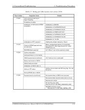
..."CHGBIOSA.EXE" /"CHGFIRMA.EXE" from the root directory. 2 Troubleshooting Procedures 2.4 System Board Troubleshooting Table 2-5 Debug port (Boot mode) error status (2/10) D port status Inspection items F00AH Saving key scan code A setup of TASK_1 second_TSC F00BH...input Reading CHGBIOSA.EXE / CHGFIRMA.EXE F00CH Blinks orange (cycle: 2s(On:1s,Off:1s)) Prohibition of USB BEEP Waiting for key input FDC reset Setting parameters for 2DD (720KB) Retrieval of "CHGBIOSA.EXE" from ... entry of "CHGBIOSA.EXE" and "CHGFIRMA.EXE" 2-20 [CONFIDENTIAL] PORTEGE R500 Maintenance Manual (960-634)
..."CHGBIOSA.EXE" /"CHGFIRMA.EXE" from the root directory. 2 Troubleshooting Procedures 2.4 System Board Troubleshooting Table 2-5 Debug port (Boot mode) error status (2/10) D port status Inspection items F00AH Saving key scan code A setup of TASK_1 second_TSC F00BH...input Reading CHGBIOSA.EXE / CHGFIRMA.EXE F00CH Blinks orange (cycle: 2s(On:1s,Off:1s)) Prohibition of USB BEEP Waiting for key input FDC reset Setting parameters for 2DD (720KB) Retrieval of "CHGBIOSA.EXE" from ... entry of "CHGBIOSA.EXE" and "CHGFIRMA.EXE" 2-20 [CONFIDENTIAL] PORTEGE R500 Maintenance Manual (960-634)
Maintenance Manual
Page 67
...(1) Setting of IRT status Storing DRAM size in CMOS Resume branch (at cold boot) Details Initialization of MCHM Initialization of ICH7M.D30.Func0 Initialization of ICH7M.D31.Func1 Initialization of USB.Func0/1/2/7 Initialization of ICH7M.D31.Func3 Initialization of ICH7M.D31.Func5 Initialization of FLUTE... boot status and IRT busy flag, The rest bits are 0) Not resume when a CMOS error occurred Not resume when resume status code is not set Resume error check S3 returning error (ICH) Resume error F170H RSM_UNKNOWN_ERR SM-RAM checksum check Resume error F173H RSM_SMRAM_ERR PORTEGE R500 ...
...(1) Setting of IRT status Storing DRAM size in CMOS Resume branch (at cold boot) Details Initialization of MCHM Initialization of ICH7M.D30.Func0 Initialization of ICH7M.D31.Func1 Initialization of USB.Func0/1/2/7 Initialization of ICH7M.D31.Func3 Initialization of ICH7M.D31.Func5 Initialization of FLUTE... boot status and IRT busy flag, The rest bits are 0) Not resume when a CMOS error occurred Not resume when resume status code is not set Resume error check S3 returning error (ICH) Resume error F170H RSM_UNKNOWN_ERR SM-RAM checksum check Resume error F173H RSM_SMRAM_ERR PORTEGE R500 ...

Maintenance Manual
Page 70
2 Troubleshooting Procedures 2.4 System Board Troubleshooting Table 2-6 Debug port (Boot mode) error status (6/10) D port status Inspection items Details (F107H) Initialization... information KBC initialization VGA display off, Reset control Sound initialization PC multi-box status acquisition HC initialization, USB device connection recognition and initialization Control of built-in LAN permission/prohibition F108H PIC initialization PIC test Password ...) Making of work for automatic configuration Acquisition of PCI IRQ 2-24 [CONFIDENTIAL] PORTEGE R500 Maintenance Manual (960-634)
2 Troubleshooting Procedures 2.4 System Board Troubleshooting Table 2-6 Debug port (Boot mode) error status (6/10) D port status Inspection items Details (F107H) Initialization... information KBC initialization VGA display off, Reset control Sound initialization PC multi-box status acquisition HC initialization, USB device connection recognition and initialization Control of built-in LAN permission/prohibition F108H PIC initialization PIC test Password ...) Making of work for automatic configuration Acquisition of PCI IRQ 2-24 [CONFIDENTIAL] PORTEGE R500 Maintenance Manual (960-634)

Maintenance Manual
Page 73
...for SIO saving/restoring) Setting of font address for resume password Setting of repeat parameter for USB KB Final check of key input during IRT Storing of T_SHADOW_RAM_SIZE Update of system resource just before booting Rewriting of memory map data of INT15h E820h function Waiting for AC-Link initialization completion Renewal of...) Check for existence of target maintenance card Prohibition of unused PC card not used Setting Wakeup status data for ACPI HW initialization just before booting, Waiting for initialization completion PORTEGE R500 Maintenance Manual (960-634) [CONFIDENTIAL] 2-27
...for SIO saving/restoring) Setting of font address for resume password Setting of repeat parameter for USB KB Final check of key input during IRT Storing of T_SHADOW_RAM_SIZE Update of system resource just before booting Rewriting of memory map data of INT15h E820h function Waiting for AC-Link initialization completion Renewal of...) Check for existence of target maintenance card Prohibition of unused PC card not used Setting Wakeup status data for ACPI HW initialization just before booting, Waiting for initialization completion PORTEGE R500 Maintenance Manual (960-634) [CONFIDENTIAL] 2-27

Maintenance Manual
Page 74
2 Troubleshooting Procedures 2.4 System Board Troubleshooting Table 2-5 Debug port (Boot mode) error status (10/10) D port status F123H Inspection items IRT_SC_INT_END Details Notifies the DVI connection status to VGA BIOS (for models supporting DVI) ...Final decision of USB FDD drive information Post processing of PRE_BOOT_SETUP Clear of PWRBTN_STS Enabling POWER Button F124H FFFFH Clear of IRT status Renewal of check sum of Runtime side NOTE: Status outputted by the test means the last error detected in the debug port test. 2-28 [CONFIDENTIAL] PORTEGE R500 Maintenance Manual (960...
2 Troubleshooting Procedures 2.4 System Board Troubleshooting Table 2-5 Debug port (Boot mode) error status (10/10) D port status F123H Inspection items IRT_SC_INT_END Details Notifies the DVI connection status to VGA BIOS (for models supporting DVI) ...Final decision of USB FDD drive information Post processing of PRE_BOOT_SETUP Clear of PWRBTN_STS Enabling POWER Button F124H FFFFH Clear of IRT status Renewal of check sum of Runtime side NOTE: Status outputted by the test means the last error detected in the debug port test. 2-28 [CONFIDENTIAL] PORTEGE R500 Maintenance Manual (960...

Maintenance Manual
Page 195
...Mode (c) User Password (d) Master Password 5. Drives I/O (a) Built-in HDD (b) SATA Controller Mode PORTEGE R500 Maintenance Manual (960-634) [CONFIDENTIAL] 3-83 Boot Priority (a) Boot Priority (b) HDD Priority 6. Others (a) Core Multi-Processing (b) Dynamic CPU Frequency Mode (c) Execute-Disable ...Bit Capability (d) Auto Power On (e) Performance/Battery Life Setting (f) Beep Volume (g) Diagnostic Mode (h) USB Sleep and Charge 7. ...
...Mode (c) User Password (d) Master Password 5. Drives I/O (a) Built-in HDD (b) SATA Controller Mode PORTEGE R500 Maintenance Manual (960-634) [CONFIDENTIAL] 3-83 Boot Priority (a) Boot Priority (b) HDD Priority 6. Others (a) Core Multi-Processing (b) Dynamic CPU Frequency Mode (c) Execute-Disable ...Bit Capability (d) Auto Power On (e) Performance/Battery Life Setting (f) Beep Volume (g) Diagnostic Mode (h) USB Sleep and Charge 7. ...
Maintenance Manual
Page 203
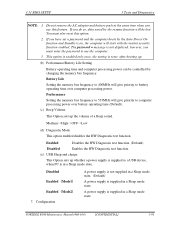
...you must also reset this feature. PORTEGE R500 Maintenance Manual (960-634) [CONFIDENTIAL] 3-91 The password = message is supplied in a Sleep mode state. Enabled Disables the HW Diagnostic test function. (Default) Disabled Enables the HW Diagnostic test function. (e) USB Sleep and charge This Option sets... not remove the AC adaptor and battery pack at the same time when you have set a password and the computer boots by the resume function will give priority to computer processing power over computer processing power. Performance Setting the memory bus frequency...
...you must also reset this feature. PORTEGE R500 Maintenance Manual (960-634) [CONFIDENTIAL] 3-91 The password = message is supplied in a Sleep mode state. Enabled Disables the HW Diagnostic test function. (Default) Disabled Enables the HW Diagnostic test function. (e) USB Sleep and charge This Option sets... not remove the AC adaptor and battery pack at the same time when you have set a password and the computer boots by the resume function will give priority to computer processing power over computer processing power. Performance Setting the memory bus frequency...

Maintenance Manual
Page 359
NOTE: 1. Connect the AC adapter to boot mode. 2. PORTEGE R500 Maintenance Manual (960-634) [CONFIDENTIAL] G-1 Turn off the power while you are rewriting the BIOS. For example (US Keyboard) (UK Keyboard) 6. In this case, insert .... Set the system to the computer when you rewrite the BIOS. 2. Remove the external cable and PC card. 4. Connect an USB FDD and insert the BIOS/EC/KBC rewriting disk into the USB FDD. 5. The BIOS rewriting starts 7. Tools To rewrite the BIOS, you need the following tool: ‰ BIOS/EC/KBC...
NOTE: 1. Connect the AC adapter to boot mode. 2. PORTEGE R500 Maintenance Manual (960-634) [CONFIDENTIAL] G-1 Turn off the power while you are rewriting the BIOS. For example (US Keyboard) (UK Keyboard) 6. In this case, insert .... Set the system to the computer when you rewrite the BIOS. 2. Remove the external cable and PC card. 4. Connect an USB FDD and insert the BIOS/EC/KBC rewriting disk into the USB FDD. 5. The BIOS rewriting starts 7. Tools To rewrite the BIOS, you need the following tool: ‰ BIOS/EC/KBC...

Maintenance Manual
Page 361
.... 2. Do not turn off . It may be displayed that the contents of the computer or ICs. Connect an USB FDD and insert the BIOS/EC/KBC rewriting disk into the USB FDD. 5. Allow sufficient time. PORTEGE R500 Maintenance Manual (960-634) [CONFIDENTIAL] H-1 Turn on the conditions of the EC/KBC have been erased. Appendix... while you update the EC/KBC system. Set the system to rewrite the EC/KBC. If the rewrite fails, it takes about 30 seconds to boot mode. 2.
.... 2. Do not turn off . It may be displayed that the contents of the computer or ICs. Connect an USB FDD and insert the BIOS/EC/KBC rewriting disk into the USB FDD. 5. Allow sufficient time. PORTEGE R500 Maintenance Manual (960-634) [CONFIDENTIAL] H-1 Turn on the conditions of the EC/KBC have been erased. Appendix... while you update the EC/KBC system. Set the system to rewrite the EC/KBC. If the rewrite fails, it takes about 30 seconds to boot mode. 2.

User Manual
Page 123
...changes and closes the HW Setup window. User's Manual 7-1 Chapter 7 HW Setup & BIOS Setup This chapter explains how to use the TOSHIBA HW Setup program to be configured. In addition there are also three buttons : OK, Cancel and Apply. OK Accepts your changes without ...To run the HW Setup program, click Start -> All Programs -> TOSHIBA -> Utilities -> HWSetup. HW Setup window The HW Setup window contains a number of tabs (General, Display, Boot Priority, Keyboard, CPU, LAN, Device Config and USB) to allow specific functions of the computer to configure your changes. ...
...changes and closes the HW Setup window. User's Manual 7-1 Chapter 7 HW Setup & BIOS Setup This chapter explains how to use the TOSHIBA HW Setup program to be configured. In addition there are also three buttons : OK, Cancel and Apply. OK Accepts your changes without ...To run the HW Setup program, click Start -> All Programs -> TOSHIBA -> Utilities -> HWSetup. HW Setup window The HW Setup window contains a number of tabs (General, Display, Boot Priority, Keyboard, CPU, LAN, Device Config and USB) to allow specific functions of the computer to configure your changes. ...

User Manual
Page 125
... LAN. CD-ROM*2, 3. hard disk drive, 2. LAN, 3. floppy diskette drive*1, 4. M Selects the USB memory drive. *1 The floppy diskette drive will be used to start the computer when there is booting: U Selects the USB floppy diskette drive. CD-ROM*2, 4. LAN, 4. CD-ROM −> LAN −> FDD −> ...computer is a bootable disk contained in hard disk drive. User's Manual 7-3 hard disk drive, 4. HW Setup & BIOS Setup Boot Priority Boot Priority Options This tab allows you to start the computer when there is a bootable disk contained in the external drive. You ...
... LAN. CD-ROM*2, 3. hard disk drive, 2. LAN, 3. floppy diskette drive*1, 4. M Selects the USB memory drive. *1 The floppy diskette drive will be used to start the computer when there is booting: U Selects the USB floppy diskette drive. CD-ROM*2, 4. LAN, 4. CD-ROM −> LAN −> FDD −> ...computer is a bootable disk contained in hard disk drive. User's Manual 7-3 hard disk drive, 4. HW Setup & BIOS Setup Boot Priority Boot Priority Options This tab allows you to start the computer when there is a bootable disk contained in the external drive. You ...

User Manual
Page 126
...(Default). The following icons: Built-in hard disk drive, CD-ROM, FDD (or SD memory card), Network (LAN), USB Memory boot. Please note that a highlighted bar will continue to boot according to the current and available settings in HW Setup. In addition, if you want and press ENTER. User's Manual 7-4...displayed. the first hard disk drive detected that has a valid boot command on the first detected hard disk drive, the system will not boot from which the computer will not change the boot drive, follow the steps below. 1. USB -> Built-in HDD This option sets the priority as the ...
...(Default). The following icons: Built-in hard disk drive, CD-ROM, FDD (or SD memory card), Network (LAN), USB Memory boot. Please note that a highlighted bar will continue to boot according to the current and available settings in HW Setup. In addition, if you want and press ENTER. User's Manual 7-4...displayed. the first hard disk drive detected that has a valid boot command on the first detected hard disk drive, the system will not boot from which the computer will not change the boot drive, follow the steps below. 1. USB -> Built-in HDD This option sets the priority as the ...

User Manual
Page 127
... a hard disk drive based on the hard disk drive settings within the Boot Priority option detailed previously. With this setting, the USB memory device can turn on the system by pressing any key. HW Setup & BIOS Setup USB Memory BIOS Support Type This option allows you can be used as a ...computer is in Sleep Mode, you to set the type of the USB memory to be used to start the computer as though it were a floppy diskette based on the floppy diskette drive settings within both the Boot Priority and HDD Priority options detailed previously. Keyboard Wake-up on Keyboard...
... a hard disk drive based on the hard disk drive settings within the Boot Priority option detailed previously. With this setting, the USB memory device can turn on the system by pressing any key. HW Setup & BIOS Setup USB Memory BIOS Support Type This option allows you can be used as a ...computer is in Sleep Mode, you to set the type of the USB memory to be used to start the computer as though it were a floppy diskette based on the floppy diskette drive settings within both the Boot Priority and HDD Priority options detailed previously. Keyboard Wake-up on Keyboard...
User Manual
Page 166
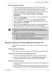
... following procedures to the hard disk drive. Creating the Intel® Matrix Storage Manager Disk 1. Windows Setup Procedure 1. User's Manual D-2 Connect the USB floppy diskette drive and insert the above disk. 2. Select "Intel(R) 82801GBM SATA AHCI Controller" from the CD. The system may not function correctly ... such as Linux, to run application that read from the DVD. Insert the Windows Setup CD-ROM into the optical disc drive and boot the computer from or right to manually set up Windows, create an Intel® Matrix Storage Manager Disk. Intel® Matrix Storage ...
... following procedures to the hard disk drive. Creating the Intel® Matrix Storage Manager Disk 1. Windows Setup Procedure 1. User's Manual D-2 Connect the USB floppy diskette drive and insert the above disk. 2. Select "Intel(R) 82801GBM SATA AHCI Controller" from the CD. The system may not function correctly ... such as Linux, to run application that read from the DVD. Insert the Windows Setup CD-ROM into the optical disc drive and boot the computer from or right to manually set up Windows, create an Intel® Matrix Storage Manager Disk. Intel® Matrix Storage ...

User Manual
Page 195
...7-8 Bluetooth 3-4, 4-25 Bluetooth 2.0+EDR Module Kit 3-27 Bluetooth Stack for Windows by Toshiba 3-9 Bluetooth USB Adaptor 3-26 problems 8-19 Wireless Optical Mouse 3-27 Wireless Stereo Headset 3-27 Boot Priority 7-3 C Cleaning the computer 4-29 Cooling vents 2-2 D DC IN indicator 2-10...Equipment checklist 1-1 External monitor 2-2, 3-21 problems 8-17 F Fingerprint Sensor location 2-7 problems 8-14 using 4-2 Floppy diskette care 4-21 FN + 1 (TOSHIBA Zooming Utility reduce) 5-5 FN + 2 (TOSHIBA Zooming Utility enlarge) 5-5 FN + ENTER 5-3 FN + ESC (Mute) 5-3 FN + F1 (Lock) 5-3 FN + F10 (Arrow Mode) ...
...7-8 Bluetooth 3-4, 4-25 Bluetooth 2.0+EDR Module Kit 3-27 Bluetooth Stack for Windows by Toshiba 3-9 Bluetooth USB Adaptor 3-26 problems 8-19 Wireless Optical Mouse 3-27 Wireless Stereo Headset 3-27 Boot Priority 7-3 C Cleaning the computer 4-29 Cooling vents 2-2 D DC IN indicator 2-10...Equipment checklist 1-1 External monitor 2-2, 3-21 problems 8-17 F Fingerprint Sensor location 2-7 problems 8-14 using 4-2 Floppy diskette care 4-21 FN + 1 (TOSHIBA Zooming Utility reduce) 5-5 FN + 2 (TOSHIBA Zooming Utility enlarge) 5-5 FN + ENTER 5-3 FN + ESC (Mute) 5-3 FN + F1 (Lock) 5-3 FN + F10 (Arrow Mode) ...

User Manual
Page 196
PORTÉGÉ R500 FN + F2 (Power Plan) 5-3 FN + F3 (Sleep) 5-4 FN + F4 (Hibernate) 5-4 FN + F5 (Output) 5-4 FN + F6 (Brightness Down) 5-4 FN + F7 (Brightness... 5-4 Brightness Up 5-4 Hibernate 5-4 Lock 5-3 Mute 5-3 ODD 5-5 Output 5-4 Power Plan 5-3 Sleep 5-4 TOSHIBA Zooming Utility (enlarge) 5-5 TOSHIBA Zooming Utility (reduce) 5-5 Touch Pad 5-4 Wireless 5-4 Zoom 5-4 HW Setup accessing 7-1 Boot priority 7-3 CPU 7-6 device config 7-7 display 7-2 general 7-2 keyboard 7-5 LAN 7-6 USB 7-7 window 7-1 I i.LINK 2-2 connecting 3-24 disconnecting 3-24 precautions 3-23 problems 8-18 Indicators 2-10 ...
PORTÉGÉ R500 FN + F2 (Power Plan) 5-3 FN + F3 (Sleep) 5-4 FN + F4 (Hibernate) 5-4 FN + F5 (Output) 5-4 FN + F6 (Brightness Down) 5-4 FN + F7 (Brightness... 5-4 Brightness Up 5-4 Hibernate 5-4 Lock 5-3 Mute 5-3 ODD 5-5 Output 5-4 Power Plan 5-3 Sleep 5-4 TOSHIBA Zooming Utility (enlarge) 5-5 TOSHIBA Zooming Utility (reduce) 5-5 Touch Pad 5-4 Wireless 5-4 Zoom 5-4 HW Setup accessing 7-1 Boot priority 7-3 CPU 7-6 device config 7-7 display 7-2 general 7-2 keyboard 7-5 LAN 7-6 USB 7-7 window 7-1 I i.LINK 2-2 connecting 3-24 disconnecting 3-24 precautions 3-23 problems 8-18 Indicators 2-10 ...

User Manual
Page 197
...Pad control buttons 2-8, 4-1 Touch Pad location 2-7 using 4-1 Power conditions 6-1 Hibernation Mode 1-10 indicators 6-2 panel on/off 3-6, 6-15 Shut Down mode (Boot Mode) 1-7 Sleep Mode 1-8 System Auto Off 6-15 turning off 1-7 turning on 1-7 Problems AC power 8-5 Additional memory module 8-15 Analyzing the problem ... Manual PORTÉGÉ R500 Pointing device 8-12 Power 8-4 Real Time Clock 8-7 Recovery Discs 8-19 SD/SDHC Card 8-11 Self test 8-4 Sound system 8-16 System start-up 8-4 TOSHIBA support 8-21 Touch Pad 8-12 USB device 8-15 USB floppy diskette drive 8-10 USB mouse 8-13 Wireless LAN ...
...Pad control buttons 2-8, 4-1 Touch Pad location 2-7 using 4-1 Power conditions 6-1 Hibernation Mode 1-10 indicators 6-2 panel on/off 3-6, 6-15 Shut Down mode (Boot Mode) 1-7 Sleep Mode 1-8 System Auto Off 6-15 turning off 1-7 turning on 1-7 Problems AC power 8-5 Additional memory module 8-15 Analyzing the problem ... Manual PORTÉGÉ R500 Pointing device 8-12 Power 8-4 Real Time Clock 8-7 Recovery Discs 8-19 SD/SDHC Card 8-11 Self test 8-4 Sound system 8-16 System start-up 8-4 TOSHIBA support 8-21 Touch Pad 8-12 USB device 8-15 USB floppy diskette drive 8-10 USB mouse 8-13 Wireless LAN ...

User Manual
Page 198
T TOSHIBA Assist 3-9 TOSHIBA Assist button 3-5 TOSHIBA ConfigFree 3-9 TOSHIBA Disc Creator 3-10, 4-17 TOSHIBA DVD-RAM Utility 3-10 TOSHIBA HDD Protection 3-6 TOSHIBA PC Diagnostic Tool 3-7 TOSHIBA SD Memory Boot Utility 3-9 TOSHIBA SD Memory Card Format 3-9 TOSHIBA Slim Port Replicator II 3-26 TOSHIBA Value Added Package 3-7 TOSHIBA Zooming Utility 3-7 U USB device problems 8-15 USB FDD Kit 3-22 USB floppy diskette drive problems 8-10 V Video RAM 3-2 Volume control dial 2-3 W Windows...
T TOSHIBA Assist 3-9 TOSHIBA Assist button 3-5 TOSHIBA ConfigFree 3-9 TOSHIBA Disc Creator 3-10, 4-17 TOSHIBA DVD-RAM Utility 3-10 TOSHIBA HDD Protection 3-6 TOSHIBA PC Diagnostic Tool 3-7 TOSHIBA SD Memory Boot Utility 3-9 TOSHIBA SD Memory Card Format 3-9 TOSHIBA Slim Port Replicator II 3-26 TOSHIBA Value Added Package 3-7 TOSHIBA Zooming Utility 3-7 U USB device problems 8-15 USB FDD Kit 3-22 USB floppy diskette drive problems 8-10 V Video RAM 3-2 Volume control dial 2-3 W Windows...


