
Maintenance Manual
Page 3
... to use only the same model battery or an equivalent battery recommended by Toshiba. PORTÉGÉ R400 Maintenance Manual (960-623))[CONFIDENTIAL] iii DANGER: "Danger" indicates the existence of a short circuit, which could result in the field. If a screw is not observed. Each of the wrong battery can cause the battery to perform hardware service maintenance for the Toshiba Personal Computer PORTÉGÉ R500. Installation of...
... to use only the same model battery or an equivalent battery recommended by Toshiba. PORTÉGÉ R400 Maintenance Manual (960-623))[CONFIDENTIAL] iii DANGER: "Danger" indicates the existence of a short circuit, which could result in the field. If a screw is not observed. Each of the wrong battery can cause the battery to perform hardware service maintenance for the Toshiba Personal Computer PORTÉGÉ R500. Installation of...
Maintenance Manual
Page 7
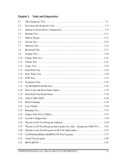
... Test...3-52 3.24 Floppy Disk Drive Utilities 3-53 3.25 System Configuration 3-58 3.26 Wireless LAN Test Program (Athetos 3-60 3.27 Wireless LAN Test Program (Intel-made b/g, a/b/g Setting up of REF PC)........ 3-62 3.28 Wireless LAN Test Program on DUT PC(Intel-made 3-67 3.29 LAN/Modem/Bluetooth/IEEE1394 Test Program 3-75 3.30 Sound Test program 3-82 3.31 BIOS SETUP ...3-83 PORTÉGÉ R400 Maintenance Manual (960-623))[CONFIDENTIAL...
... Test...3-52 3.24 Floppy Disk Drive Utilities 3-53 3.25 System Configuration 3-58 3.26 Wireless LAN Test Program (Athetos 3-60 3.27 Wireless LAN Test Program (Intel-made b/g, a/b/g Setting up of REF PC)........ 3-62 3.28 Wireless LAN Test Program on DUT PC(Intel-made 3-67 3.29 LAN/Modem/Bluetooth/IEEE1394 Test Program 3-75 3.30 Sound Test program 3-82 3.31 BIOS SETUP ...3-83 PORTÉGÉ R400 Maintenance Manual (960-623))[CONFIDENTIAL...
Maintenance Manual
Page 63
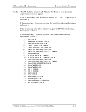
... 2.9. (1) PIT ERROR (2) MEMORY REFRESH ERROR (3) TIMER CH.2 OUT ERROR (4) CMOS CHECKSUM ERROR (5) CMOS BAD BATTERY ERROR (6) FIRST 64KB MEMORY ERROR (7) FIRST 64KB MEMORY PARITY ERROR (8) VRAM ERROR (9) SYSTEM MEMORY ERROR (10) SYSTEM MEMORY PARITY ERROR (11) EXTENDED MEMORY ERROR (12) EXTENDED MEMORY PARITY ERROR (13) DMA PAGE REGISTER ERROR (14) DMAC #1 ERROR (15) DMAC #2 ERROR (16) PIC #1 ERROR (17) PIC #2 ERROR (18) KBC ERROR (19) HDC ERROR (20) Built-in HDD ERROR (21) Select Bay ERROR (22) TIMER INTERRUPT ERROR (23) RTC UPDATE ERROR PORTEGE R500 Maintenance Manual (960...
... 2.9. (1) PIT ERROR (2) MEMORY REFRESH ERROR (3) TIMER CH.2 OUT ERROR (4) CMOS CHECKSUM ERROR (5) CMOS BAD BATTERY ERROR (6) FIRST 64KB MEMORY ERROR (7) FIRST 64KB MEMORY PARITY ERROR (8) VRAM ERROR (9) SYSTEM MEMORY ERROR (10) SYSTEM MEMORY PARITY ERROR (11) EXTENDED MEMORY ERROR (12) EXTENDED MEMORY PARITY ERROR (13) DMA PAGE REGISTER ERROR (14) DMAC #1 ERROR (15) DMAC #2 ERROR (16) PIC #1 ERROR (17) PIC #2 ERROR (18) KBC ERROR (19) HDC ERROR (20) Built-in HDD ERROR (21) Select Bay ERROR (22) TIMER INTERRUPT ERROR (23) RTC UPDATE ERROR PORTEGE R500 Maintenance Manual (960...
Maintenance Manual
Page 147
... - SERIAL ID WRITE ERROR ROM - SENSING ERROR(1st Batt) ROM - GET DESCR.ERROR(Top 8B) HUB - CLEAR FEATURE2 ERROR USB - CHECKSUM ERROR ROM - NOT SUPPORTED PS-SYSTEM ROM - GET DESCR.ERROR (Whole) HUB - OVER CURRENT ERROR USB - GET DESCR.ERROR(SECOND) VRAM SIZE NOT SUPPORT PORTEGE R500 Maintenance Manual (960-634) [CONFIDENTIAL] 3-35 SENSING ERROR(AC-ADAPT) ROM - PROTECTED MODE NO CHANGE' RAM - SET CONFIGURATION ERROR HUB - GET DESCR.ERROR (FIRST) USB - CLEAR FEATURE ERROR HUB - THORMISTOR ERROR(3) RAM - SET FEATURE ERROR(P ON) HUB - 3.18 Error Code and Error...
... - SERIAL ID WRITE ERROR ROM - SENSING ERROR(1st Batt) ROM - GET DESCR.ERROR(Top 8B) HUB - CLEAR FEATURE2 ERROR USB - CHECKSUM ERROR ROM - NOT SUPPORTED PS-SYSTEM ROM - GET DESCR.ERROR (Whole) HUB - OVER CURRENT ERROR USB - GET DESCR.ERROR(SECOND) VRAM SIZE NOT SUPPORT PORTEGE R500 Maintenance Manual (960-634) [CONFIDENTIAL] 3-35 SENSING ERROR(AC-ADAPT) ROM - PROTECTED MODE NO CHANGE' RAM - SET CONFIGURATION ERROR HUB - GET DESCR.ERROR (FIRST) USB - CLEAR FEATURE ERROR HUB - THORMISTOR ERROR(3) RAM - SET FEATURE ERROR(P ON) HUB - 3.18 Error Code and Error...

Maintenance Manual
Page 148
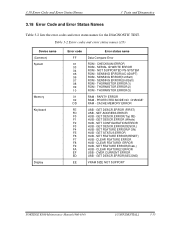
... ERROR HDD - TIME OUT ERROR FDD - WRITE BUFFER ERROR PRT - BAD COMMAND ERROR HDD - DRIVE NOT READY 3-36 [CONFIDENTIAL] PORTEGE R500 Maintenance Manual (960-634) CRC ERROR FDD - OUT OF PAPER PRT - ADDRESS MARK NOT FOUND HDD - ECC RECOVER ENABLE HDD - HDC ERROR HDD - MODEM STATUS ERROR SIR - BAD TRACK ERROR HDD - TIME OUT PRT - TIME OUT ERROR FIR - SEEK ERROR HDD - ECC ERROR HDD - 3 Tests and Diagnostics 3.18 Error Code and Error Status Names Table 3-2 Error codes and error status names (2/3) Device...
... ERROR HDD - TIME OUT ERROR FDD - WRITE BUFFER ERROR PRT - BAD COMMAND ERROR HDD - DRIVE NOT READY 3-36 [CONFIDENTIAL] PORTEGE R500 Maintenance Manual (960-634) CRC ERROR FDD - OUT OF PAPER PRT - ADDRESS MARK NOT FOUND HDD - ECC RECOVER ENABLE HDD - HDC ERROR HDD - MODEM STATUS ERROR SIR - BAD TRACK ERROR HDD - TIME OUT PRT - TIME OUT ERROR FIR - SEEK ERROR HDD - ECC ERROR HDD - 3 Tests and Diagnostics 3.18 Error Code and Error Status Names Table 3-2 Error codes and error status names (2/3) Device...

Maintenance Manual
Page 228
...;4B STEP Memory cover Figure 4-4 Removing the memory module (1) 4-12 [CONFIDENTIAL] PORTÉGÉ R500 Maintenance Manual (960-634) 4 Replacement Procedures 4.5 Memory module 4.5 Memory module Removing the Memory module CAUTION: The power must be turned off , follow the steps below and refer to Figure 4-4 and 4-5. 1. Dust and stains on might damage the module or the computer itself. Inserting a memory module with the power on the connectors may cause memory access problems. Never press hard or bend the memory module.
...;4B STEP Memory cover Figure 4-4 Removing the memory module (1) 4-12 [CONFIDENTIAL] PORTÉGÉ R500 Maintenance Manual (960-634) 4 Replacement Procedures 4.5 Memory module 4.5 Memory module Removing the Memory module CAUTION: The power must be turned off , follow the steps below and refer to Figure 4-4 and 4-5. 1. Dust and stains on might damage the module or the computer itself. Inserting a memory module with the power on the connectors may cause memory access problems. Never press hard or bend the memory module.
User Manual
Page 8
.... This powerful notebook computer provides excellent expansion capability, includes multimedia functionality, and is organized, then become acquainted with this computer, as well as the section on Chapter 7, HW Setup & BIOS Setup, to understand how to familiarize yourself with the computer's features, components and accessory devices. Read Chapter 3, Hardware, Utilities and Options if connecting optional products or external devices. For example: Read Only Memory (ROM). This manual tells...
.... This powerful notebook computer provides excellent expansion capability, includes multimedia functionality, and is organized, then become acquainted with this computer, as well as the section on Chapter 7, HW Setup & BIOS Setup, to understand how to familiarize yourself with the computer's features, components and accessory devices. Read Chapter 3, Hardware, Utilities and Options if connecting optional products or external devices. For example: Read Only Memory (ROM). This manual tells...
User Manual
Page 27
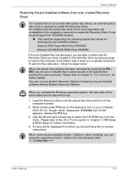
... heard before starting the restore process. When removing pre-installed drivers / utilities or when installing, you can not use the Recovery Discs you reinstall the Windows operating system, the hard disk will be reformatted and all data will be displayed from which you originally received it. Getting Started Restoring the pre-installed software from your computer when the In Touch with optical disc drives, an external optical disc drive is required to the Boot Priority section...
... heard before starting the restore process. When removing pre-installed drivers / utilities or when installing, you can not use the Recovery Discs you reinstall the Windows operating system, the hard disk will be reformatted and all data will be displayed from which you originally received it. Getting Started Restoring the pre-installed software from your computer when the In Touch with optical disc drives, an external optical disc drive is required to the Boot Priority section...

User Manual
Page 57
... either Sleep or Hibernation Mode. User's Manual 3-16 The wireless communication switch is turned on using memory cards, see manuals accompanying the cards. Hardware, Utilities and Options Memory card care ■ Set the write-protect switch to the lock position, if you do not touch any other foreign matter fall into the computer in progress. Low power could cause malfunction or electric shock. ■ Additional memory module is a precision electronic component that may be installed...
... either Sleep or Hibernation Mode. User's Manual 3-16 The wireless communication switch is turned on using memory cards, see manuals accompanying the cards. Hardware, Utilities and Options Memory card care ■ Set the write-protect switch to the lock position, if you do not touch any other foreign matter fall into the computer in progress. Low power could cause malfunction or electric shock. ■ Additional memory module is a precision electronic component that may be installed...

User Manual
Page 58
... install a memory module which keeps the total system memory, inclusive of the main board memory module, within 2,048MB. Use a point size 0 Phillips screwdriver. User's Manual 3-17 Set the computer to Boot Mode and turn its power off the power section in Chapter 1, Getting Started if required). 2. In all instances you should shut down and remove the battery pack (refer to remove and fasten the screws the use of the computer, the Power indicator...
... install a memory module which keeps the total system memory, inclusive of the main board memory module, within 2,048MB. Use a point size 0 Phillips screwdriver. User's Manual 3-17 Set the computer to Boot Mode and turn its power off the power section in Chapter 1, Getting Started if required). 2. In all instances you should shut down and remove the battery pack (refer to remove and fasten the screws the use of the computer, the Power indicator...

User Manual
Page 60
... memory module cover in place please note that this screw is off (refer to ensure that the memory module cover is recognized - Turn the computer on and make sure the Power indicator is attached to prevent it , Start -> Control Panel -> System and Maintenance > System icon. Set the computer to Boot Mode and turn its power off the power section in order to the cover in Chapter 1, Getting Started if required). 2. make sure the added memory...
... memory module cover in place please note that this screw is off (refer to ensure that the memory module cover is recognized - Turn the computer on and make sure the Power indicator is attached to prevent it , Start -> Control Panel -> System and Maintenance > System icon. Set the computer to Boot Mode and turn its power off the power section in order to the cover in Chapter 1, Getting Started if required). 2. make sure the added memory...
User Manual
Page 66
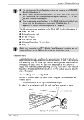
... jack ■ Security lock slot ■ Universal Serial Bus 2.0 port (four) ■ DVI port As the port operation of the security cable, while the other heavy object in place. Connecting the security lock In order to connect a security cable to help prevent unauthorized removal or theft. The following computer's ports: LAN jack, DC IN 15V jack and External monitor port. ■ When connecting an AC Adaptor to product. The methods used for more information. Turn...
... jack ■ Security lock slot ■ Universal Serial Bus 2.0 port (four) ■ DVI port As the port operation of the security cable, while the other heavy object in place. Connecting the security lock In order to connect a security cable to help prevent unauthorized removal or theft. The following computer's ports: LAN jack, DC IN 15V jack and External monitor port. ■ When connecting an AC Adaptor to product. The methods used for more information. Turn...

User Manual
Page 88
... format. 3. About Straight to Disc ■ Not support to a slow device like a USB1.1 hard disk drive or it . About recorded DVDs ■ Some DVD-ROM drives for personal computers or other function, including using a mouse or Touch Pad, or closing/opening the display panel. ■ Bump or cause vibration to the computer. ■ Use the Mode control button and Audio/Video control button to reproduce music or voice. ■ Open the DVD drive. ■ Install, remove or connect external devices, including the following actions: ■ Operate...
... format. 3. About Straight to Disc ■ Not support to a slow device like a USB1.1 hard disk drive or it . About recorded DVDs ■ Some DVD-ROM drives for personal computers or other function, including using a mouse or Touch Pad, or closing/opening the display panel. ■ Bump or cause vibration to the computer. ■ Use the Mode control button and Audio/Video control button to reproduce music or voice. ■ Open the DVD drive. ■ Install, remove or connect external devices, including the following actions: ■ Operate...

User Manual
Page 102
... keyboard - User's Manual 5-2 The Keyboard Function keys: F1 ... Soft keys are not restored when the computer returns from other keys to provide all the features of one on the 104/105 key enhanced keyboard which are using two keys instead of the 104key enhanced keyboard. F12 The function keys (not to note that the soft-key settings are key combinations that enable, disable or configure specific features. Emulating keys on an enhanced keyboard Figure 5-1 A 104-key...
... keyboard - User's Manual 5-2 The Keyboard Function keys: F1 ... Soft keys are not restored when the computer returns from other keys to provide all the features of one on the 104/105 key enhanced keyboard which are using two keys instead of the 104key enhanced keyboard. F12 The function keys (not to note that the soft-key settings are key combinations that enable, disable or configure specific features. Emulating keys on an enhanced keyboard Figure 5-1 A 104-key...
User Manual
Page 142
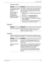
... using the RTC battery is not remapping the keyboard in the BIOS setup application by the setup and configuration of each key). Press the Y key - please refer to ensure that the numeric keypad overlay is will need to the TOSHIBA Password Utility section in the System Date field. Press the F1 key - inconsistent. 2. Keyboard Keyboard problems can be displayed. 5. a confirmation message will restart. Password Problem Procedure Cannot enter password Please refer to set...
... using the RTC battery is not remapping the keyboard in the BIOS setup application by the setup and configuration of each key). Press the Y key - please refer to ensure that the numeric keypad overlay is will need to the TOSHIBA Password Utility section in the System Date field. Press the F1 key - inconsistent. 2. Keyboard Keyboard problems can be displayed. 5. a confirmation message will restart. Password Problem Procedure Cannot enter password Please refer to set...
User Manual
Page 152
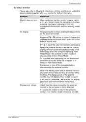
... external monitor. If you should check the connections to make sure that the cable connecting the external monitor to a working power outlet. To keep this occurs, press FN + F5 to re-set to resolve the problem, contact your monitor for the internal display only. Display error occurs Check that the power cord/adaptor is firmly connected to the monitor and to the computer is set as the primary display device in Sleep Mode. User's Manual 8-17 Problem Procedure Monitor...
... external monitor. If you should check the connections to make sure that the cable connecting the external monitor to a working power outlet. To keep this occurs, press FN + F5 to re-set to resolve the problem, contact your monitor for the internal display only. Display error occurs Check that the power cord/adaptor is firmly connected to the monitor and to the computer is set as the primary display device in Sleep Mode. User's Manual 8-17 Problem Procedure Monitor...
User Manual
Page 166
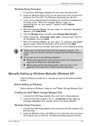
... install Windows?" Continue to follow the onscreen instructions to the floppy diskette. Insert the Windows Setup CD-ROM into the optical disc drive and boot the computer from the list that appear, and click Next. 7. The Windows Setup program will start . User's Manual D-2 Click the Browse button and then select Floppy Disk Drive(A:). 6. Before Setting up Windows Before setting up Windows, create an Intel® Matrix Storage Manager Disk. Intel® Matrix Storage Manager Windows Setup Procedure 1. Connect the USB...
... install Windows?" Continue to follow the onscreen instructions to the floppy diskette. Insert the Windows Setup CD-ROM into the optical disc drive and boot the computer from the list that appear, and click Next. 7. The Windows Setup program will start . User's Manual D-2 Click the Browse button and then select Floppy Disk Drive(A:). 6. Before Setting up Windows Before setting up Windows, create an Intel® Matrix Storage Manager Disk. Intel® Matrix Storage Manager Windows Setup Procedure 1. Connect the USB...

User Manual
Page 186
.... device driver: A program that controls the functions of a specific internal or peripheral device (e.g. If data bits = 7 the computer can generate 128 unique characters. keyboard controller). CPU: Central Processing Unit. DC: Direct Current. The portion of the computer that define how your system (such as the terminal, printer, and disk drives) and the settings that interprets and executes instructions. delete: To remove data from the keyboard to make...
.... device driver: A program that controls the functions of a specific internal or peripheral device (e.g. If data bits = 7 the computer can generate 128 unique characters. keyboard controller). CPU: Central Processing Unit. DC: Direct Current. The portion of the computer that define how your system (such as the terminal, printer, and disk drives) and the settings that interprets and executes instructions. delete: To remove data from the keyboard to make...

User Manual
Page 189
... specify how to set the parameters for example, the keyboard or a menu. instruction: Statements or commands that the user can be used specifically to connect one system or device to another. 2) To physically connect one system or device to the 10th power. i.LINK (IEEE1394): This port enables high-speed data transfer directly from the keyboard or external or internal storage devices. Glossary hexadecimal: The base 16 numbering system composed...
... specify how to set the parameters for example, the keyboard or a menu. instruction: Statements or commands that the user can be used specifically to connect one system or device to another. 2) To physically connect one system or device to the 10th power. i.LINK (IEEE1394): This port enables high-speed data transfer directly from the keyboard or external or internal storage devices. Glossary hexadecimal: The base 16 numbering system composed...
User Manual
Page 190
.... mode: A method of the liquid crystal. MP3: An audio compression standard that perform special functions. Glossary keyboard: An input device containing switches that carries out instructions. The viewingside coating is applied. microprocessor: A hardware component contained in turn, representative of options on the screen. User's Manual Glossary-9 kilobyte (KB): A unit of up to display alphanumeric characters or graphic images. Light Emitting Diode (LED): A semiconductor device that emits light when...
.... mode: A method of the liquid crystal. MP3: An audio compression standard that perform special functions. Glossary keyboard: An input device containing switches that carries out instructions. The viewingside coating is applied. microprocessor: A hardware component contained in turn, representative of options on the screen. User's Manual Glossary-9 kilobyte (KB): A unit of up to display alphanumeric characters or graphic images. Light Emitting Diode (LED): A semiconductor device that emits light when...


