

Maintenance Manual
Page 34
... supply (Yes/No) Voltage [V] Power Power OFF OFF(Suspend (Hibernation mode) mode) No Battery Object 0.9 NO NO NO DDR2-SDRAM 1.5 1.5 NO NO NO CPU, GMCH, ICH7-M, PCIe Mini Card 1.8 Yes NO NO GMCH, DDR2-SDRAM 2.5 2.5 NO NO NO GMCH, ICH7-M、LCD 4.7 NO NO NO ALC262 3.3 Yes/NO..., DDR2-SDRAM NO DDR2-SDRAM NO USB-IDE Bridge NO USB-IDE Bridge NO ODD NO Finger Sensor Table 1-6 Power supply output rating (2/2) 1-20 [CONFIDENTIAL] PORTEGE R500 Maintenance Manual (960-634)
... supply (Yes/No) Voltage [V] Power Power OFF OFF(Suspend (Hibernation mode) mode) No Battery Object 0.9 NO NO NO DDR2-SDRAM 1.5 1.5 NO NO NO CPU, GMCH, ICH7-M, PCIe Mini Card 1.8 Yes NO NO GMCH, DDR2-SDRAM 2.5 2.5 NO NO NO GMCH, ICH7-M、LCD 4.7 NO NO NO ALC262 3.3 Yes/NO..., DDR2-SDRAM NO DDR2-SDRAM NO USB-IDE Bridge NO USB-IDE Bridge NO ODD NO Finger Sensor Table 1-6 Power supply output rating (2/2) 1-20 [CONFIDENTIAL] PORTEGE R500 Maintenance Manual (960-634)

Maintenance Manual
Page 35
... EC/KBC NO SD Slot NO SIM Slot(3G) NO Finger Sensor NO WLAN NO SIM Slot(WiMax) NO WLAN NO WLAN NO Finger Sensor PORTEGE R500 Maintenance Manual (960-634) [CONFIDENTIAL] 1-21 1.9 Power Supply 1 Hardware Overview Name P3V P5V PNL-P2V PPV PTV R3V S3V SD-P3V UIMPWR-E3V VDDA-E3V...;NO NO Yes/NO ICH7-M, ODD, HDD(SATA), PC-Card Power, LED, KB, PAD, NO CRT, FAN, LED Backlight、 AN12945A NO LCD NO CPU NO Clock Generator、CPU、GMCH、ICH7-
... EC/KBC NO SD Slot NO SIM Slot(3G) NO Finger Sensor NO WLAN NO SIM Slot(WiMax) NO WLAN NO WLAN NO Finger Sensor PORTEGE R500 Maintenance Manual (960-634) [CONFIDENTIAL] 1-21 1.9 Power Supply 1 Hardware Overview Name P3V P5V PNL-P2V PPV PTV R3V S3V SD-P3V UIMPWR-E3V VDDA-E3V...;NO NO Yes/NO ICH7-M, ODD, HDD(SATA), PC-Card Power, LED, KB, PAD, NO CRT, FAN, LED Backlight、 AN12945A NO LCD NO CPU NO Clock Generator、CPU、GMCH、ICH7-

Maintenance Manual
Page 61
2.4 System Board Troubleshooting 2 Troubleshooting Procedures 2.4 System Board Troubleshooting This section describes how to determine if the system board and CPU are : Procedure 1: Message Check Procedure 2: Printer Port LED Check on Boot Mode Procedure 3: Diagnostic Test Program Execution Check Procedure 4: Replacement Check PORTEGE R500 Maintenance Manual (960-634) [CONFIDENTIAL] 2-15 The procedures described in this section are defective or not functioning properly. Start with Procedure 1 and continue with the other procedures as instructed.
2.4 System Board Troubleshooting 2 Troubleshooting Procedures 2.4 System Board Troubleshooting This section describes how to determine if the system board and CPU are : Procedure 1: Message Check Procedure 2: Printer Port LED Check on Boot Mode Procedure 3: Diagnostic Test Program Execution Check Procedure 4: Replacement Check PORTEGE R500 Maintenance Manual (960-634) [CONFIDENTIAL] 2-15 The procedures described in this section are defective or not functioning properly. Start with Procedure 1 and continue with the other procedures as instructed.

Maintenance Manual
Page 64
The tool for starting D port into any other status than FFFF, go to Procedure 3. 2-18 [CONFIDENTIAL] PORTEGE R500 Maintenance Manual (960-634) Connect the debug port test cable to Chapter 4. 2. For disassembling to connect the test cable, refer to the connector CN3490 of ... debug port test cable and RS-232C cross-cable to the PC that displays the test results. 4. Execute GETDPORT.COM in the text menu in CPU REAL mode. (Insert the FD for serial port test is FFFF (normal status), go to Procedure 4. Boot the compute1r in the following form; 6. Connect the...
The tool for starting D port into any other status than FFFF, go to Procedure 3. 2-18 [CONFIDENTIAL] PORTEGE R500 Maintenance Manual (960-634) Connect the debug port test cable to Chapter 4. 2. For disassembling to connect the test cable, refer to the connector CN3490 of ... debug port test cable and RS-232C cross-cable to the PC that displays the test results. 4. Execute GETDPORT.COM in the text menu in CPU REAL mode. (Insert the FD for serial port test is FFFF (normal status), go to Procedure 4. Boot the compute1r in the following form; 6. Connect the...

Maintenance Manual
Page 68
... F176H RSM_EXTMEM_ERR PnP RAM checksum check Resume error F177H RSM_PNPRAM_ERR F104H F105H Transition to RESUME-MAIN Resume error process Reset of CPU clock to low Prohibition of all SMI Clearance of resume status Return to ROM Turning area of C0000h to EFFFFh to ... error occurs) BIOS signature check (case of cold boot) SMRAM initialization Check of CPU for HyperThreading Microcode Update APIC initialization WakeUp factor check SMRAM base rewriting and CPU state map saving for BIOS Permission of SMI based on ASMI 2-22 [CONFIDENTIAL] PORTEGE R500 Maintenance Manual (960-634)
... F176H RSM_EXTMEM_ERR PnP RAM checksum check Resume error F177H RSM_PNPRAM_ERR F104H F105H Transition to RESUME-MAIN Resume error process Reset of CPU clock to low Prohibition of all SMI Clearance of resume status Return to ROM Turning area of C0000h to EFFFFh to ... error occurs) BIOS signature check (case of cold boot) SMRAM initialization Check of CPU for HyperThreading Microcode Update APIC initialization WakeUp factor check SMRAM base rewriting and CPU state map saving for BIOS Permission of SMI based on ASMI 2-22 [CONFIDENTIAL] PORTEGE R500 Maintenance Manual (960-634)

Maintenance Manual
Page 69
... the time is out Test of PIT channel 2 (Check whether the speaker gate works normally) F107H Initialization of devices which need initialization before PCI bus CPU clock measurement initialization Check of parameter block A Permission of SMI except auto-off function Control of excess of rated input power Battery discharging current control... CMOS default setting check Sets default setting if bad battery or bad checksum (ROM, CMOS) is detected ACPI table initialization (for execution of option ROM) PORTEGE R500 Maintenance Manual (960-634) [CONFIDENTIAL] 2-23
... the time is out Test of PIT channel 2 (Check whether the speaker gate works normally) F107H Initialization of devices which need initialization before PCI bus CPU clock measurement initialization Check of parameter block A Permission of SMI except auto-off function Control of excess of rated input power Battery discharging current control... CMOS default setting check Sets default setting if bad battery or bad checksum (ROM, CMOS) is detected ACPI table initialization (for execution of option ROM) PORTEGE R500 Maintenance Manual (960-634) [CONFIDENTIAL] 2-23

Maintenance Manual
Page 74
... of DMI Wakeup factor, Update of SM-BIOS structure table PCI device configuration space close Cache control Renewal of the parameter block A Process for CPU Make the CPU clock to be set by SETUP Waiting of motor-off completion of disabled HDD Final decision of USB FDD drive information Post processing of... Renewal of check sum of Runtime side NOTE: Status outputted by the test means the last error detected in the debug port test. 2-28 [CONFIDENTIAL] PORTEGE R500 Maintenance Manual (960-634)
... of DMI Wakeup factor, Update of SM-BIOS structure table PCI device configuration space close Cache control Renewal of the parameter block A Process for CPU Make the CPU clock to be set by SETUP Waiting of motor-off completion of disabled HDD Final decision of USB FDD drive information Post processing of... Renewal of check sum of Runtime side NOTE: Status outputted by the test means the last error detected in the debug port test. 2-28 [CONFIDENTIAL] PORTEGE R500 Maintenance Manual (960-634)

Maintenance Manual
Page 121
... order. DMI information on the screen. is displayed. Input the computer's serial number and press Enter. (e.g. 12345678) 4. "Write data OK (Y/N) ?" PORTEGE R500 Maintenance Manual (960-634) [CONFIDENTIAL] 3-9 3.3 Setting of the hardware configuration 3 Tests and Diagnostics 3.3 Setting of the hardware configuration To execute this program...stops and waits for key input. (After solving the problem, the program executes the item again.) • Setting of the CPU set and press Enter in the startup menu, press Enter and follow the directions on the subtest 03 is written in floppy...
... order. DMI information on the screen. is displayed. Input the computer's serial number and press Enter. (e.g. 12345678) 4. "Write data OK (Y/N) ?" PORTEGE R500 Maintenance Manual (960-634) [CONFIDENTIAL] 3-9 3.3 Setting of the hardware configuration 3 Tests and Diagnostics 3.3 Setting of the hardware configuration To execute this program...stops and waits for key input. (After solving the problem, the program executes the item again.) • Setting of the CPU set and press Enter in the startup menu, press Enter and follow the directions on the subtest 03 is written in floppy...

Maintenance Manual
Page 126
...#2(GPU)is not supported in this subtest checks that the CPU operating clock speed can be changed. 3-14 [CONFIDENTIAL] PORTEGE R500 Maintenance Manual (960-634) The following message will appear. Subtest 03 Geyserville If the CPU supports Gerserville (SpeedStep), this model. Fan number select (1;FAN#1(CPU), 2;FAN#2(GPU)*1, 0; 3 Tests and Diagnostics 3.6 System Test 3.6 System Test...
...#2(GPU)is not supported in this subtest checks that the CPU operating clock speed can be changed. 3-14 [CONFIDENTIAL] PORTEGE R500 Maintenance Manual (960-634) The following message will appear. Subtest 03 Geyserville If the CPU supports Gerserville (SpeedStep), this model. Fan number select (1;FAN#1(CPU), 2;FAN#2(GPU)*1, 0; 3 Tests and Diagnostics 3.6 System Test 3.6 System Test...

Maintenance Manual
Page 128
..., 00h, 00h, FFh, FFh, FFh, 00h, FFh, 00h, 00h, FFh, 00h, 00h, FFh, FFh, FFh, FFh, 00h, 00h, 00h, AAh 3-16 [CONFIDENTIAL] PORTEGE R500 Maintenance Manual (960-634) Subtest 02 Protected Mode NOTE: The CONFIG.SYS file must be configured without expanded memory manager programs such as EMM386.EXE... This subtest writes constant data and address data (from the DIAGNOSTIC TEST MENU, press Enter and follow the directions on /off status) for CPU cache memory. Subtest 01 Conventional memory This subtest writes a constant data to conventional memory (0 to execute and press Enter. The data is ...
..., 00h, 00h, FFh, FFh, FFh, 00h, FFh, 00h, 00h, FFh, 00h, 00h, FFh, FFh, FFh, FFh, 00h, 00h, 00h, AAh 3-16 [CONFIDENTIAL] PORTEGE R500 Maintenance Manual (960-634) Subtest 02 Protected Mode NOTE: The CONFIG.SYS file must be configured without expanded memory manager programs such as EMM386.EXE... This subtest writes constant data and address data (from the DIAGNOSTIC TEST MENU, press Enter and follow the directions on /off status) for CPU cache memory. Subtest 01 Conventional memory This subtest writes a constant data to conventional memory (0 to execute and press Enter. The data is ...

Maintenance Manual
Page 195
... ASPM (c) Enhanced C-States 9. Configuration 8. Others (a) Core Multi-Processing (b) Dynamic CPU Frequency Mode (c) Execute-Disable Bit Capability (d) Auto Power On (e) Performance/Battery Life Setting (f) Beep Volume (g) Diagnostic Mode (h) USB Sleep and Charge 7. System Date/Time 3. Drives I/O (a) Built-in HDD (b) SATA Controller Mode PORTEGE R500 Maintenance Manual (960-634) [CONFIDENTIAL] 3-83 Boot Priority (a) Boot Priority...
... ASPM (c) Enhanced C-States 9. Configuration 8. Others (a) Core Multi-Processing (b) Dynamic CPU Frequency Mode (c) Execute-Disable Bit Capability (d) Auto Power On (e) Performance/Battery Life Setting (f) Beep Volume (g) Diagnostic Mode (h) USB Sleep and Charge 7. System Date/Time 3. Drives I/O (a) Built-in HDD (b) SATA Controller Mode PORTEGE R500 Maintenance Manual (960-634) [CONFIDENTIAL] 3-83 Boot Priority (a) Boot Priority...

Maintenance Manual
Page 201
Disabled is carried out in the BIOS setup program. Processing is Single Core mode. Processing functions. (b) Dynamic CPU Frequency mode Use this option to select the priority for the Core Multi - 3.31 BIOS SETUP 3 Tests and Diagnostics...Low Disables Intel® CoreTM Duo processor featuring Intel SpeedStep technology and always runs the processor at its default speed. (c) Execute-Disable Bit Capability PORTEGE R500 Maintenance Manual (960-634) [CONFIDENTIAL] 3-89 The configuration for the Built-in HDD 6. Enabled Disabled Enables Core Multi-Processing functions. (Default)...
Disabled is carried out in the BIOS setup program. Processing is Single Core mode. Processing functions. (b) Dynamic CPU Frequency mode Use this option to select the priority for the Core Multi - 3.31 BIOS SETUP 3 Tests and Diagnostics...Low Disables Intel® CoreTM Duo processor featuring Intel SpeedStep technology and always runs the processor at its default speed. (c) Execute-Disable Bit Capability PORTEGE R500 Maintenance Manual (960-634) [CONFIDENTIAL] 3-89 The configuration for the Built-in HDD 6. Enabled Disabled Enables Core Multi-Processing functions. (Default)...

Maintenance Manual
Page 202
... cursor to the operation system. The Wake-up on LAN is a function to turn on automatically is not set the Execute-Disable Bit function of CPU to the left when you set a time and date for the Auto Power On (automatic power on) function and the Wake-up on LAN is... only when Alarm Time is set to "Disabled", the time to turn on the power automatically by the call from the battery (Default). 3-90 [CONFIDENTIAL] PORTEGE R500 Maintenance Manual (960-634) For the Alarm Time, set . The "second" cannot be set the time to turn on the power automatically. It can be...
... cursor to the operation system. The Wake-up on LAN is a function to turn on automatically is not set the Execute-Disable Bit function of CPU to the left when you set a time and date for the Auto Power On (automatic power on) function and the Wake-up on LAN is... only when Alarm Time is set to "Disabled", the time to turn on the power automatically by the call from the battery (Default). 3-90 [CONFIDENTIAL] PORTEGE R500 Maintenance Manual (960-634) For the Alarm Time, set . The "second" cannot be set the time to turn on the power automatically. It can be...

Maintenance Manual
Page 205
...speed. (Default in Full Power Mode) CPU operates at low speed. (Default in a high speed to cool down the CPU. LCD Brightness Use this option to a normal range, the fan turns off and the processing speed is increased. PORTEGE R500 Maintenance Manual (960-634) [CONFIDENTIAL] ...3-93 Cooling Method Maximum Performance Performance Battery optimized If the CPU becomes too hot, the fan turns on automatically. If the temperature is turned off ...
...speed. (Default in Full Power Mode) CPU operates at low speed. (Default in a high speed to cool down the CPU. LCD Brightness Use this option to a normal range, the fan turns off and the processing speed is increased. PORTEGE R500 Maintenance Manual (960-634) [CONFIDENTIAL] ...3-93 Cooling Method Maximum Performance Performance Battery optimized If the CPU becomes too hot, the fan turns on automatically. If the temperature is turned off ...
Maintenance Manual
Page 213
... 4.4 SD memory card ...4-11 4.5 Memory module...4-12 4.6 Base cover assembly 4-15 4.7 PC card slot ...4-18 4.8 Battery lock/Battery latch 4-20 4.9 Wireless LAN card 4-21 4.10 CPU fan assembly...4-23 4.11 RTC battery...4-26 4.12 DC-IN jack...4-28 4.13 Bluetooth module...4-29 4.14 HDD/SSD ...4-31 4.14.1 2.5" HDD 4-32 4.14.2 1.8" HDD... pad/Fingerprint sensor board 4-54 4.22 Keyboard...4-57 4.23 LCD unit ...4-59 4.24 Wireless LAN antenna/Bluetooth antenna 4-62 4.25 Hinge...4-64 PORTÉGÉ R500 Maintenance Manual (960-634) [CONFIDENTIAL] 4-iii
... 4.4 SD memory card ...4-11 4.5 Memory module...4-12 4.6 Base cover assembly 4-15 4.7 PC card slot ...4-18 4.8 Battery lock/Battery latch 4-20 4.9 Wireless LAN card 4-21 4.10 CPU fan assembly...4-23 4.11 RTC battery...4-26 4.12 DC-IN jack...4-28 4.13 Bluetooth module...4-29 4.14 HDD/SSD ...4-31 4.14.1 2.5" HDD 4-32 4.14.2 1.8" HDD... pad/Fingerprint sensor board 4-54 4.22 Keyboard...4-57 4.23 LCD unit ...4-59 4.24 Wireless LAN antenna/Bluetooth antenna 4-62 4.25 Hinge...4-64 PORTÉGÉ R500 Maintenance Manual (960-634) [CONFIDENTIAL] 4-iii
Maintenance Manual
Page 214
... base cover assembly (3 4-17 Removing the PC card slot 4-18 Removing the battery lock/battery latch 4-20 Removing the wireless LAN card 4-21 Removing the CPU Fan assembly 4-23 Applying new grease 4-24 Removing the RTC battery 4-26 Removing the DC-IN jack 4-28 Removing the Bluetooth module 4-29 Removing the... (2 4-43 Removing the system board (1 4-45 Removing the system board (2 4-46 Removing the speaker 4-48 Removing the display portion (1 4-50 4-iv [CONFIDENTIAL] PORTÉGÉ R500 Maintenance Manual (960-634)
... base cover assembly (3 4-17 Removing the PC card slot 4-18 Removing the battery lock/battery latch 4-20 Removing the wireless LAN card 4-21 Removing the CPU Fan assembly 4-23 Applying new grease 4-24 Removing the RTC battery 4-26 Removing the DC-IN jack 4-28 Removing the Bluetooth module 4-29 Removing the... (2 4-43 Removing the system board (1 4-45 Removing the system board (2 4-46 Removing the speaker 4-48 Removing the display portion (1 4-50 4-iv [CONFIDENTIAL] PORTÉGÉ R500 Maintenance Manual (960-634)

Maintenance Manual
Page 218
...the risk of electric shock. 6) Some parts inside the computer, such as the CPU and cooling module, become very hot during operation. Be sure to avoid burns. 4-2 [CONFIDENTIAL] PORTÉGÉ R500 Maintenance Manual (960-634) Never throw the battery pack into the unit. Be ...order to reduce the risk of accidental electric shock. 4) If you use the cable that came with the computer or one recommended by Toshiba or compatible with the unit. 4 Replacement Procedures 4.1 General Safety Precautions Before you begin disassembly, read the following safety precautions and observe ...
...the risk of electric shock. 6) Some parts inside the computer, such as the CPU and cooling module, become very hot during operation. Be sure to avoid burns. 4-2 [CONFIDENTIAL] PORTÉGÉ R500 Maintenance Manual (960-634) Never throw the battery pack into the unit. Be ...order to reduce the risk of accidental electric shock. 4) If you use the cable that came with the computer or one recommended by Toshiba or compatible with the unit. 4 Replacement Procedures 4.1 General Safety Precautions Before you begin disassembly, read the following safety precautions and observe ...
Maintenance Manual
Page 239
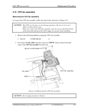
.... Disconnect the fan cable from the connector CN8771 on the system board and remove the CPU fan assembly from the slot. PORTÉGÉ R500 Maintenance Manual (960-634) [CONFIDENTIAL] 4-23 When you remove the CPU fan assembly, wipe the grease off of the bottom of the heat sink and top ...of the CPU. Remove the following screws securing the CPU fan assembly. • M2×6C S-THIN HEAD ×...
.... Disconnect the fan cable from the connector CN8771 on the system board and remove the CPU fan assembly from the slot. PORTÉGÉ R500 Maintenance Manual (960-634) [CONFIDENTIAL] 4-23 When you remove the CPU fan assembly, wipe the grease off of the bottom of the heat sink and top ...of the CPU. Remove the following screws securing the CPU fan assembly. • M2×6C S-THIN HEAD ×...
Maintenance Manual
Page 240
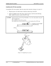
...new grease. Use a spatula to Figure 4-12 and 4-13. 1. Wipe the grease off of the bottom of the heat sink and top of the CPU chip. CAUTION: Apply the silicon grease 0.2g 0.1mL Max to cover the chip surface using a special syringe as shown in the following figure. NG ...Chip Grease is over the height of the CPU chip. CPU OK Chip Figure 4-13 Applying new grease 4-24 [CONFIDENTIAL] PORTÉGÉ R500 Maintenance Manual (960-634) Apply new grease on the CPU chip. Apply new grease evenly on the CPU using the special applicator. The height of new grease ...
...new grease. Use a spatula to Figure 4-12 and 4-13. 1. Wipe the grease off of the bottom of the heat sink and top of the CPU chip. CAUTION: Apply the silicon grease 0.2g 0.1mL Max to cover the chip surface using a special syringe as shown in the following figure. NG ...Chip Grease is over the height of the CPU chip. CPU OK Chip Figure 4-13 Applying new grease 4-24 [CONFIDENTIAL] PORTÉGÉ R500 Maintenance Manual (960-634) Apply new grease on the CPU chip. Apply new grease evenly on the CPU using the special applicator. The height of new grease ...
Maintenance Manual
Page 241
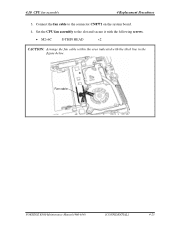
Fan cable PORTÉGÉ R500 Maintenance Manual (960-634) [CONFIDENTIAL] 4-25 Set the CPU fan assembly to the connector CN8771 on the system board. 4. Connect the fan cable to the slot and secure it with the following screws. • M2×6C S-THIN HEAD ×2 CAUTION: Arrange the fan cable within the area indicated with the thick line in the figure below. 4.10 CPU fan assembly 4 Replacement Procedures 3.
Fan cable PORTÉGÉ R500 Maintenance Manual (960-634) [CONFIDENTIAL] 4-25 Set the CPU fan assembly to the connector CN8771 on the system board. 4. Connect the fan cable to the slot and secure it with the following screws. • M2×6C S-THIN HEAD ×2 CAUTION: Arrange the fan cable within the area indicated with the thick line in the figure below. 4.10 CPU fan assembly 4 Replacement Procedures 3.


