
Service Manual
Page 9
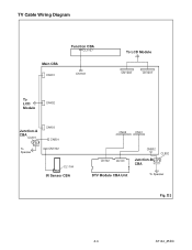
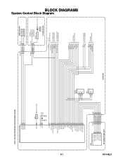
TV Cable Wiring Diagram Main CBA CN401 Function CBA CL1107 CN1301 To LCD Module CN1202 CN1201 To LCD Module CN402 Junction-A CBA CL801 To Speaker CN403 CN801 CN1302 CL1104 IR Sensor CBA CN62 CN61 CN102 CN101 CN802 Junction-B CBA CL802 DTV Module CBA Unit To Speaker Fig. D3 4-4 A7144_45DC
TV Cable Wiring Diagram Main CBA CN401 Function CBA CL1107 CN1301 To LCD Module CN1202 CN1201 To LCD Module CN402 Junction-A CBA CL801 To Speaker CN403 CN801 CN1302 CL1104 IR Sensor CBA CN62 CN61 CN102 CN101 CN802 Junction-B CBA CL802 DTV Module CBA Unit To Speaker Fig. D3 4-4 A7144_45DC
Service Manual
Page 13
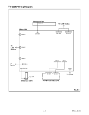
D3 4-8 A7144_45DC TV Cable Wiring Diagram Main CBA CN401 Function CBA CL1107 CN1301 To LCD Module CN1202 CN1201 To LCD Module CN402 To Speaker CN403 CN801 CN1302 CL1104 IR Sensor CBA CN62 CN61 CN102 CN101 DTV Module CBA Unit CN802 To Speaker Fig.
D3 4-8 A7144_45DC TV Cable Wiring Diagram Main CBA CN401 Function CBA CL1107 CN1301 To LCD Module CN1202 CN1201 To LCD Module CN402 To Speaker CN403 CN801 CN1302 CL1104 IR Sensor CBA CN62 CN61 CN102 CN101 DTV Module CBA Unit CN802 To Speaker Fig.
Service Manual
Page 14
... after all repairs and replacements have been completed. Initial Setting General: Enter Service mode. DC Voltmeter 2. NOTE: Electrical adjustments are required after [MENU] on the TV unit simultaneously in the standby mode. 1. It is available.
... after all repairs and replacements have been completed. Initial Setting General: Enter Service mode. DC Voltmeter 2. NOTE: Electrical adjustments are required after [MENU] on the TV unit simultaneously in the standby mode. 1. It is available.
Service Manual
Page 15
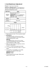
... and "y" value are not within specification, adjust "CCOB(C/D2)" or "C-COR(C/D2)". Initial Setting." 7. Operate the unit for pure white. Press [VOL -] button on the TV unit.) L = 3 cm INPUT: WHITE 80%, 20% Color Analyzer Note: Use the service remote control unit 1. Test Point Adj. Perpendicularity [INPUT2] Enter the Service mode. Refer...
... and "y" value are not within specification, adjust "CCOB(C/D2)" or "C-COR(C/D2)". Initial Setting." 7. Operate the unit for pure white. Press [VOL -] button on the TV unit.) L = 3 cm INPUT: WHITE 80%, 20% Color Analyzer Note: Use the service remote control unit 1. Test Point Adj. Perpendicularity [INPUT2] Enter the Service mode. Refer...
Service Manual
Page 16
... unit and press [1] on the service remote control (selecting "BRT" mode). [INPUT2] Press [MENU] button on the service remote control unit and press [3] on the TV unit.) 5-3 A7144EA Make sure that contrast and brightness controls are set to bright. 5. Confirm "C" position was beginning to bright, no need to be obtained by...
... unit and press [1] on the service remote control (selecting "BRT" mode). [INPUT2] Press [MENU] button on the service remote control unit and press [3] on the TV unit.) 5-3 A7144EA Make sure that contrast and brightness controls are set to bright. 5. Confirm "C" position was beginning to bright, no need to be obtained by...
Service Manual
Page 17
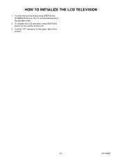
To enter the service mode, press [MENU] and [POWER] buttons on the remote control unit. 3. To initialize the LCD television, press [DISPLAY] button on the TV unit simultaneously in the standby mode. 2. Confirm "FF" indication on the upper right of the screen. 6-1 A7144INT HOW TO INITIALIZE THE LCD TELEVISION 1.
To enter the service mode, press [MENU] and [POWER] buttons on the remote control unit. 3. To initialize the LCD television, press [DISPLAY] button on the TV unit simultaneously in the standby mode. 2. Confirm "FF" indication on the upper right of the screen. 6-1 A7144INT HOW TO INITIALIZE THE LCD TELEVISION 1.
Service Manual
Page 28
IC1202 (TV MICRO CONTROLLER) KEY-IN-2 4 KEY-IN-1 3 REMOTE 27 RESET 94 XIN 37 XOUT 38 Q917 RESET AL+3.3V(D) X1301 27MHz VCOM 19 DTV-ON-H 152 ...
IC1202 (TV MICRO CONTROLLER) KEY-IN-2 4 KEY-IN-1 3 REMOTE 27 RESET 94 XIN 37 XOUT 38 Q917 RESET AL+3.3V(D) X1301 27MHz VCOM 19 DTV-ON-H 152 ...
Service Manual
Page 36
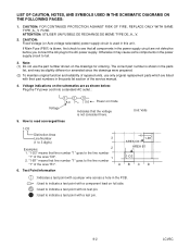
... cause some components in the power supply circuit are listed with a test pin. 9-2 LCVSC Voltage indications on the schematics are as shown below: Plug the TV power cord into a standard AC outlet.: Voltage 1 2 5.0 3 5.0 Power on the drawings for ordering. LIST OF CAUTION, NOTES, AND SYMBOLS USED IN THE SCHEMATIC DIAGRAMS ON...
... cause some components in the power supply circuit are listed with a test pin. 9-2 LCVSC Voltage indications on the schematics are as shown below: Plug the TV power cord into a standard AC outlet.: Voltage 1 2 5.0 3 5.0 Power on the drawings for ordering. LIST OF CAUTION, NOTES, AND SYMBOLS USED IN THE SCHEMATIC DIAGRAMS ON...
Service Manual
Page 51
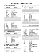
... Address 1 Input 3 A2 Slave Address 2 Input 4 GND GND 5 SDA Serial Data 6 SCL Serial Clock 7 WP Write Protect 8 VCC VCC IC1202 (LCD Drive / LCD Signal Process / TV Micro Controller) Pin No. Signal Name Function 4 KEY-IN-2 Key Input 2 5 AFT-IN AFT Voltage Input 6 PROTECT-1 Power Supply Protection 1 7 PROTECT-2 Power Supply Protection 2 8 PROTECT...
... Address 1 Input 3 A2 Slave Address 2 Input 4 GND GND 5 SDA Serial Data 6 SCL Serial Clock 7 WP Write Protect 8 VCC VCC IC1202 (LCD Drive / LCD Signal Process / TV Micro Controller) Pin No. Signal Name Function 4 KEY-IN-2 Key Input 2 5 AFT-IN AFT Voltage Input 6 PROTECT-1 Power Supply Protection 1 7 PROTECT-2 Power Supply Protection 2 8 PROTECT...


