
Service Manual
Page 14
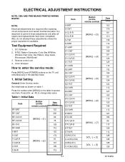
... on the TV unit simultaneously in the standby mode. 1. NOTE: Electrical adjustments are required after all repairs and replacements have been completed. Remote control unit 4. Table 1: Initial Data Item RF-BRT RF-CNT RF-CLR-R RF-CLR-B RF-TNT RF-SHR V-BRT V-CNT V-CLR... table 1. It is important to change data value. o / p] to perform these adjustments unless the proper equipment is available. Press the number after [MENU] on the remote control) [MENU] → [3] [MENU] → [4] [MENU] → [5] [MENU] → [6] [MENU] → [7] [VOL -] → [1] [VOL -] → [3] ...
... on the TV unit simultaneously in the standby mode. 1. NOTE: Electrical adjustments are required after all repairs and replacements have been completed. Remote control unit 4. Table 1: Initial Data Item RF-BRT RF-CNT RF-CLR-R RF-CLR-B RF-TNT RF-SHR V-BRT V-CNT V-CLR... table 1. It is important to change data value. o / p] to perform these adjustments unless the proper equipment is available. Press the number after [MENU] on the remote control) [MENU] → [3] [MENU] → [4] [MENU] → [5] [MENU] → [6] [MENU] → [7] [VOL -] → [1] [VOL -] → [3] ...
Service Manual
Page 15
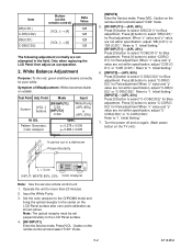
...to select "DB(C/D1)" for Red adjustment. Initial Setting." 7. Symptom of Misadjustment: White becomes bluish or reddish. Press [VOL -] button on the remote control unit and select "C/D2" mode. 5. [RF/INPUT1]----(APL 80%) Press [6] button to select "DR(C/D1)" for Blue adjustment. When "x" value..., adjust "DB (C/D1)" or "DR (C/D1)". Press [4] button to "1. Item DR(C/D1) C-DR(C/D2) DB(C/D1) C-DB(C/D2) Button (on the remote control) [VOL -] → [4] [VOL -] → [6] Data Value 128 128 128 128 The following adjustment normally are not attempted in a darkroom. Pattern...
...to select "DB(C/D1)" for Red adjustment. Initial Setting." 7. Symptom of Misadjustment: White becomes bluish or reddish. Press [VOL -] button on the remote control unit and select "C/D2" mode. 5. [RF/INPUT1]----(APL 80%) Press [6] button to select "DR(C/D1)" for Blue adjustment. When "x" value..., adjust "DB (C/D1)" or "DR (C/D1)". Press [4] button to "1. Item DR(C/D1) C-DR(C/D2) DB(C/D1) C-DB(C/D2) Button (on the remote control) [VOL -] → [4] [VOL -] → [6] Data Value 128 128 128 128 The following adjustment normally are not attempted in a darkroom. Pattern...
Service Manual
Page 16
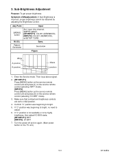
...brightness. Spec. Then input above signal. 2. [RF/INPUT1] Press [MENU] button on the service remote control unit and press [1] on the service remote control (selecting "BRT" mode). [INPUT2] Press [MENU] button on the service remote control unit and press [3] on the TV unit.) 5-3 A7144EA If "C" position was beginning to adjust....not available or to initial position. 4. Adj. Turn the power off and on again. (Main power button on the service remote control (selecting "D1-BRT" mode). 3. Pattern Generator See below Figure White A position B position Black C position 1.
...brightness. Spec. Then input above signal. 2. [RF/INPUT1] Press [MENU] button on the service remote control unit and press [1] on the service remote control (selecting "BRT" mode). [INPUT2] Press [MENU] button on the service remote control unit and press [3] on the TV unit.) 5-3 A7144EA If "C" position was beginning to adjust....not available or to initial position. 4. Adj. Turn the power off and on again. (Main power button on the service remote control (selecting "D1-BRT" mode). 3. Pattern Generator See below Figure White A position B position Black C position 1.
Service Manual
Page 17
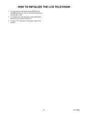
HOW TO INITIALIZE THE LCD TELEVISION 1. Confirm "FF" indication on the TV unit simultaneously in the standby mode. 2. To enter the service mode, press [MENU] and [POWER] buttons on the upper right of the screen. 6-1 A7144INT To initialize the LCD television, press [DISPLAY] button on the remote control unit. 3.
HOW TO INITIALIZE THE LCD TELEVISION 1. Confirm "FF" indication on the TV unit simultaneously in the standby mode. 2. To enter the service mode, press [MENU] and [POWER] buttons on the upper right of the screen. 6-1 A7144INT To initialize the LCD television, press [DISPLAY] button on the remote control unit. 3.
Service Manual
Page 18
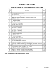
...-ON+1.8V is not output. 7-6 19 PANEL-6V is not output. 7-6 20 The key operation is not functioning. 7-6 21 No operation is possible from the remote control unit. 7-7 22 Picture does not appear normally. (Tuner input (Analog) / Video input/S-Video input) 7-8 23 Picture does not appear normally. (Tuner input (Digital)) 7-8 24...
...-ON+1.8V is not output. 7-6 19 PANEL-6V is not output. 7-6 20 The key operation is not functioning. 7-6 21 No operation is possible from the remote control unit. 7-7 22 Picture does not appear normally. (Tuner input (Analog) / Video input/S-Video input) 7-8 23 Picture does not appear normally. (Tuner input (Digital)) 7-8 24...

Service Manual
Page 24
... the line between Pin(1) terminal of receiver (RV1142) and Pin(3) of CN1302? Operation is possible from the remote control unit. Replace the infrared remote control receiver (RV1142) or the remote control unit. No Yes Check IC1202 and the periphery circuit, and service it if defective. 7-7 A7144_45TS Yes... Is the "L" pulse sent out Pin(1) terminal of the No infrared remote control receiver (RV1142)? Is 3.3V voltage supplied to the Pin(3) of CN1302 , and service it if defective. Check AL+3.3V(D) line...
... the line between Pin(1) terminal of receiver (RV1142) and Pin(3) of CN1302? Operation is possible from the remote control unit. Replace the infrared remote control receiver (RV1142) or the remote control unit. No Yes Check IC1202 and the periphery circuit, and service it if defective. 7-7 A7144_45TS Yes... Is the "L" pulse sent out Pin(1) terminal of the No infrared remote control receiver (RV1142)? Is 3.3V voltage supplied to the Pin(3) of CN1302 , and service it if defective. Check AL+3.3V(D) line...
Service Manual
Page 28
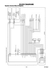
IC1202 (TV MICRO CONTROLLER) KEY-IN-2 4 KEY-IN-1 3 REMOTE 27 RESET 94 XIN 37 XOUT 38 Q917 RESET AL+3.3V(D) X1301 27MHz VCOM 19 DTV-ON-H 152 BACKLIGHT-SW 157 P-ON-H 28 VGH-H 26 ... (MEMORY) 7 WP 5 SDA 6 SCL IC61 (MEMORY) 5 SDA 6 SCL MAIN CBA CN1301 1 KEY-IN-2 2 KEY-IN-1 CL1107 1 2 FUNCTION CBA KEY SWITCH KEY SWITCH CN1302 3 REMOTE 4 P-ON-H CL1104 3 4 RV1142 REMOTE SENSOR Q1142 LED DRIVE D1142 POWER AL+3.3V(D) IR SENSOR CBA VCOM DTV-ON-H BACKLIGHT-SW P-ON-H VGH-H BACKLIGHT-ADJ TO LCD BLOCK DIAGRAM...
IC1202 (TV MICRO CONTROLLER) KEY-IN-2 4 KEY-IN-1 3 REMOTE 27 RESET 94 XIN 37 XOUT 38 Q917 RESET AL+3.3V(D) X1301 27MHz VCOM 19 DTV-ON-H 152 BACKLIGHT-SW 157 P-ON-H 28 VGH-H 26 ... (MEMORY) 7 WP 5 SDA 6 SCL IC61 (MEMORY) 5 SDA 6 SCL MAIN CBA CN1301 1 KEY-IN-2 2 KEY-IN-1 CL1107 1 2 FUNCTION CBA KEY SWITCH KEY SWITCH CN1302 3 REMOTE 4 P-ON-H CL1104 3 4 RV1142 REMOTE SENSOR Q1142 LED DRIVE D1142 POWER AL+3.3V(D) IR SENSOR CBA VCOM DTV-ON-H BACKLIGHT-SW P-ON-H VGH-H BACKLIGHT-ADJ TO LCD BLOCK DIAGRAM...
Service Manual
Page 50
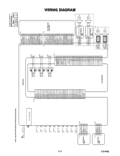
...-Y IN VIDEO-Pb IN VIDEO-Pr IN AUDIO(R) -IN1 AUDIO(L) -IN1 AUDIO(R) -IN2 AUDIO(L) -IN2 DIGITAL AUDIO-OUT CL1104 1 2 IR SENSOR 3 CBA 4 5 AL+3.3V(D) GND REMOTE P-ON-H NU CN1302 1 2 3 4 5 CN1201 1 ER [5] 2 ER [4] 3 ER [3] 4 ER [2] 5 ER [1] 6 ER [0] 7 GND 8 CLKL 9 GND 10 OB [5] 11 OB [4] 12 OB [3] 13 OB [2] 14 ... 17 18 19 20 21 22 23 24 25 26 27 28 29 30 31 32 33 Comparison Chart of Models and Marks Model Mark LC-20AV7U A LC-20SH7U B CN61 CN101 1 D-GND 1 2 DTV-SPDIF 2 3 DTV-ON+5V 3 4 TU-SCL 4 5 TU-SDA 5 6 D-GND 6 7 DTV-S-SREQ 7 8 DTV-S-SCLK 8 9 DTV-S-SIN 9 10 ...
...-Y IN VIDEO-Pb IN VIDEO-Pr IN AUDIO(R) -IN1 AUDIO(L) -IN1 AUDIO(R) -IN2 AUDIO(L) -IN2 DIGITAL AUDIO-OUT CL1104 1 2 IR SENSOR 3 CBA 4 5 AL+3.3V(D) GND REMOTE P-ON-H NU CN1302 1 2 3 4 5 CN1201 1 ER [5] 2 ER [4] 3 ER [3] 4 ER [2] 5 ER [1] 6 ER [0] 7 GND 8 CLKL 9 GND 10 OB [5] 11 OB [4] 12 OB [3] 13 OB [2] 14 ... 17 18 19 20 21 22 23 24 25 26 27 28 29 30 31 32 33 Comparison Chart of Models and Marks Model Mark LC-20AV7U A LC-20SH7U B CN61 CN101 1 D-GND 1 2 DTV-SPDIF 2 3 DTV-ON+5V 3 4 TU-SCL 4 5 TU-SDA 5 6 D-GND 6 7 DTV-S-SREQ 7 8 DTV-S-SCLK 8 9 DTV-S-SIN 9 10 ...
Service Manual
Page 51
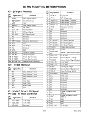
... 2 at High 23 VOLUME Volume Control Signal Output 24 VDD+1.2V +1.2V VDD 25 VDD+1.2V +1.2V VDD 26 VGH-H VGH Signal at High 27 REMOTE Remote Control Signal Input 28 P-ON-H Power On Signal at High 29 BUS-OPEN Chip select 30 SCL Serial Clock 31 SDA Serial Data 32 NU...
... 2 at High 23 VOLUME Volume Control Signal Output 24 VDD+1.2V +1.2V VDD 25 VDD+1.2V +1.2V VDD 26 VGH-H VGH Signal at High 27 REMOTE Remote Control Signal Input 28 P-ON-H Power On Signal at High 29 BUS-OPEN Chip select 30 SCL Serial Clock 31 SDA Serial Data 32 NU...
Service Manual
Page 60
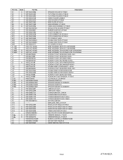
... PROTECTION SHEET A7144UH PROTECTION SHEET SIDE A7144UH PROTECTION SHEET SIDE A7145UH STAND HOLD PAD A7144UH BAG POLYETHYLENE 235X365XT0.03 OWNERS MANUAL L7144UH OWNERS MANUAL A7145UH REMOTE CONTROL ETR0088-010200 DRY BATTERY R6UW/2S REGISTRATION CARD A7121UH 14-2 A7144/45CA No. Ref.
... PROTECTION SHEET A7144UH PROTECTION SHEET SIDE A7144UH PROTECTION SHEET SIDE A7145UH STAND HOLD PAD A7144UH BAG POLYETHYLENE 235X365XT0.03 OWNERS MANUAL L7144UH OWNERS MANUAL A7145UH REMOTE CONTROL ETR0088-010200 DRY BATTERY R6UW/2S REGISTRATION CARD A7121UH 14-2 A7144/45CA No. Ref.
Service Manual
Page 75
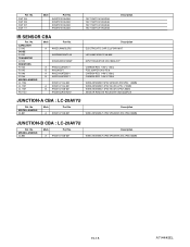
... SKQSAB TACT SWITCH SKQSAB TACT SWITCH SKQSAB Description IR SENSOR CBA Ref. No. A 9HSX1A7140-007 Description WIRE ASSEMBLY 2PIN SPEAKER 20V 2PIN/230MM JUNCTION-B CBA : LC-20AV7U Ref. A 9HSX1A7140-007 Description WIRE ASSEMBLY 2PIN SPEAKER 20V 2PIN/230MM 15-15 A7144/45EL MISCELLANEOUS CL802 Mark Part No. No. Ref. No. A 9HSE1JMAVSL2R2 9HSPWK333HTF45.... 1/4W J 220 Ω WIRE ASSEMBLY 5PIN SENSOR 20V 5PIN / 130MM WIRE ASSEMBLY 4PIN SW 20V 4PIN / 210MM WIRE ASSEMBLY 4PIN SW 20V 4PIN/128MM SENSOR REMOTE RECEIVER KSM-603SR2E JUNCTION-A CBA : LC-20AV7U Ref.
... SKQSAB TACT SWITCH SKQSAB TACT SWITCH SKQSAB Description IR SENSOR CBA Ref. No. A 9HSX1A7140-007 Description WIRE ASSEMBLY 2PIN SPEAKER 20V 2PIN/230MM JUNCTION-B CBA : LC-20AV7U Ref. A 9HSX1A7140-007 Description WIRE ASSEMBLY 2PIN SPEAKER 20V 2PIN/230MM 15-15 A7144/45EL MISCELLANEOUS CL802 Mark Part No. No. Ref. No. A 9HSE1JMAVSL2R2 9HSPWK333HTF45.... 1/4W J 220 Ω WIRE ASSEMBLY 5PIN SENSOR 20V 5PIN / 130MM WIRE ASSEMBLY 4PIN SW 20V 4PIN / 210MM WIRE ASSEMBLY 4PIN SW 20V 4PIN/128MM SENSOR REMOTE RECEIVER KSM-603SR2E JUNCTION-A CBA : LC-20AV7U Ref.


