
Service Manual
Page 1
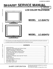
...TELEVISION LC-20AV7U/LC-20SH7U SERVICE MANUAL S37F3LC20AV7U LCD COLOR TELEVISION MODEL LC-20AV7U MODEL LC-20SH7U In the interests of user-safety (Required by safety regulations in some countries) the set should be restored to its original condition and only parts identical to change without notice. CONTENTS Page SPECIFICATIONS ...1-1 IMPORTANT SAFEGUARDS AND PRECAUTIONS 2-1 STANDARD NOTES FOR SERVICING 3-1 CABINET DISASSEMBLY INSTRUCTIONS 4-1 ELECTRICAL ADJUSTMENT INSTRUCTIONS 5-1 HOW TO INITIALIZE THE LCD TELEVISION 6-1 TROUBLESHOOTING ...7-1 BLOCK DIAGRAMS ...8-1 SCHEMATIC DIAGRAMS...
...TELEVISION LC-20AV7U/LC-20SH7U SERVICE MANUAL S37F3LC20AV7U LCD COLOR TELEVISION MODEL LC-20AV7U MODEL LC-20SH7U In the interests of user-safety (Required by safety regulations in some countries) the set should be restored to its original condition and only parts identical to change without notice. CONTENTS Page SPECIFICATIONS ...1-1 IMPORTANT SAFEGUARDS AND PRECAUTIONS 2-1 STANDARD NOTES FOR SERVICING 3-1 CABINET DISASSEMBLY INSTRUCTIONS 4-1 ELECTRICAL ADJUSTMENT INSTRUCTIONS 5-1 HOW TO INITIALIZE THE LCD TELEVISION 6-1 TROUBLESHOOTING ...7-1 BLOCK DIAGRAMS ...8-1 SCHEMATIC DIAGRAMS...
Service Manual
Page 2
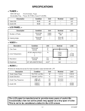
... 70 < VIDEO > Description 1. SPECIFICATIONS < TUNER > VHF/UHF Input : 75 ohm Unbal., F type Intermediate Freq. : Picture 45.75 MHz, Sound 41.25 MHz Description 1. Number of color. Over Scan 2. Response 4. Limit ------- ±0.005 ±0.005 ------- Limit >43 >45 Limit --------- Audio S/N Condition Unit 80dB dB 80dB dB Nominal ----- < LCD PANEL > Description 1. Audio Output Power 2. Resolution 4. Limit 0.8/0.8 3.0/3.0 ---->45/45 >45/45 The LCD panel is not to provide many years of useful life. Video S/N 2.
... 70 < VIDEO > Description 1. SPECIFICATIONS < TUNER > VHF/UHF Input : 75 ohm Unbal., F type Intermediate Freq. : Picture 45.75 MHz, Sound 41.25 MHz Description 1. Number of color. Over Scan 2. Response 4. Limit ------- ±0.005 ±0.005 ------- Limit >43 >45 Limit --------- Audio S/N Condition Unit 80dB dB 80dB dB Nominal ----- < LCD PANEL > Description 1. Audio Output Power 2. Resolution 4. Limit 0.8/0.8 3.0/3.0 ---->45/45 >45/45 The LCD panel is not to provide many years of useful life. Video S/N 2.
Service Manual
Page 5
... a short circuit. 3-1 LCV_NOTE FFC Cable Connector CBA 2 Using lead-free wire solder When fixing the PWB soldered with steel wool or fine sandpaper. If a different type of parts may be exceeded, remove the bit from the PWB as soon as it with the lead-free solder, apply lead-free wire solder. Be careful when replacing parts with conventional lead wire solder...
... a short circuit. 3-1 LCV_NOTE FFC Cable Connector CBA 2 Using lead-free wire solder When fixing the PWB soldered with steel wool or fine sandpaper. If a different type of parts may be exceeded, remove the bit from the PWB as soon as it with the lead-free solder, apply lead-free wire solder. Be careful when replacing parts with conventional lead wire solder...
Service Manual
Page 6
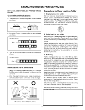
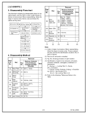
... of parts to be removed or installed. (3) Fig. showing procedure of part location (4) Identification of steps in reverse order. No. No. No. These numbers are also used as they were. [5] Function CBA [4] Rear Cabinet [1] Base Plate [12] Junction-A CBA [13] Junction-B CBA [14] Speaker (s) [6] Tilt Stand Holder [8] Jack Holder [9] DTV Module CBA Unit [2] Stand Arm Assembly [3] Stand Cover [7] IR Sensor CBA [10] Main CBA [11] LCD...
... of parts to be removed or installed. (3) Fig. showing procedure of part location (4) Identification of steps in reverse order. No. No. No. These numbers are also used as they were. [5] Function CBA [4] Rear Cabinet [1] Base Plate [12] Junction-A CBA [13] Junction-B CBA [14] Speaker (s) [6] Tilt Stand Holder [8] Jack Holder [9] DTV Module CBA Unit [2] Stand Arm Assembly [3] Stand Cover [7] IR Sensor CBA [10] Main CBA [11] LCD...
Service Manual
Page 10
... part location (4) Identification of steps in the Table. 4-5 A7144_45DC Disassembly Method Removal Step/ Remove/*Unhook/ Loc. No. Part Remove/*Unhook/ Fig. These numbers are also used as they were. [5] Function CBA [4] Rear Cabinet [1] Base Plate [12] Speaker (s) [7] IR Sensor CBA [6] Tilt Stand Holder [8] Jack Holder [9] DTV Module CBA Unit [2] Stand Arm Assembly [3] Stand Cover [10] Main CBA [11] LCD Module [13] Front Cabinet 4. Bend, route and dress the cables...
... part location (4) Identification of steps in the Table. 4-5 A7144_45DC Disassembly Method Removal Step/ Remove/*Unhook/ Loc. No. Part Remove/*Unhook/ Fig. These numbers are also used as they were. [5] Function CBA [4] Rear Cabinet [1] Base Plate [12] Speaker (s) [7] IR Sensor CBA [6] Tilt Stand Holder [8] Jack Holder [9] DTV Module CBA Unit [2] Stand Arm Assembly [3] Stand Cover [10] Main CBA [11] LCD Module [13] Front Cabinet 4. Bend, route and dress the cables...
Service Manual
Page 14
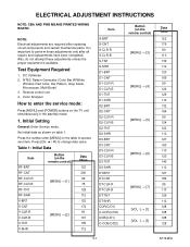
...) C-COB(C/D2) Button (on table 1. It is available. Color Analyzer How to perform these adjustments unless the proper equipment is important to enter the service mode: Press [MENU] and [POWER] buttons on the table to change data value. ELECTRICAL ADJUSTMENT INSTRUCTIONS NOTE: CBA AND PWB MEANS PRINTED WIRING BOARD. Also, do not attempt these adjustments only after replacing circuit components and certain mechanical parts. Initial Setting General: Enter Service mode.
...) C-COB(C/D2) Button (on table 1. It is available. Color Analyzer How to perform these adjustments unless the proper equipment is important to enter the service mode: Press [MENU] and [POWER] buttons on the table to change data value. ELECTRICAL ADJUSTMENT INSTRUCTIONS NOTE: CBA AND PWB MEANS PRINTED WIRING BOARD. Also, do not attempt these adjustments only after replacing circuit components and certain mechanical parts. Initial Setting General: Enter Service mode.
Service Manual
Page 15
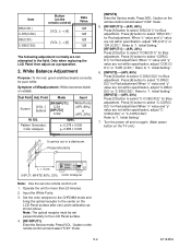
... unit.) L = 3 cm INPUT: WHITE 80%, 20% Color Analyzer Note: Use the service remote control unit 1. When "x" value and "y" value are not within specification, adjust "CCOB(C/D2)" or "C-COR(C/D2)". Refer to select "COR(C/ D1)" for Red adjustment.When "x" value and "y" value are not within specification, adjust "DB (C/D1)" or "DR (C/D1)". Initial Setting." 7. Only when replacing the LCD Panel then adjust as shown above. Point Mode Input Screen [VOL -] buttons [RF/INPUT1...
... unit.) L = 3 cm INPUT: WHITE 80%, 20% Color Analyzer Note: Use the service remote control unit 1. When "x" value and "y" value are not within specification, adjust "CCOB(C/D2)" or "C-COR(C/D2)". Refer to select "COR(C/ D1)" for Red adjustment.When "x" value and "y" value are not within specification, adjust "DB (C/D1)" or "DR (C/D1)". Initial Setting." 7. Only when replacing the LCD Panel then adjust as shown above. Point Mode Input Screen [VOL -] buttons [RF/INPUT1...
Service Manual
Page 16
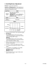
... is not available or to initial position. 4. Point Input [MENU] button Ant. Adj. Pattern Generator See below Figure White A position B position Black C position 1. Enter the Service mode. Turn the power off and on again. (Main power button on the service remote control (selecting "D1-BRT" mode). 3. Make sure that contrast and brightness controls are set to be obtained by adjusting the Brightness Control. If "C" position is incorrect, proper brightness cannot...
... is not available or to initial position. 4. Point Input [MENU] button Ant. Adj. Pattern Generator See below Figure White A position B position Black C position 1. Enter the Service mode. Turn the power off and on again. (Main power button on the service remote control (selecting "D1-BRT" mode). 3. Make sure that contrast and brightness controls are set to be obtained by adjusting the Brightness Control. If "C" position is incorrect, proper brightness cannot...
Service Manual
Page 18
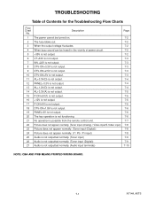
... is not output. 7-6 19 PANEL-6V is not output. 7-6 20 The key operation is not functioning. 7-6 21 No operation is possible from the remote control unit. 7-7 22 Picture does not appear normally. (Tuner input (Analog) / Video input/S-Video input) 7-8 23 Picture does not appear normally. (Tuner input (Digital)) 7-8 24 Picture does not appear normally. (Y / Pb / Pr input) 7-8 25 Audio is not outputted normally. (Tuner input) 7-9 26 Audio is not outputted normally. (Tuner input (Digital)) 7-9 27 Audio is not outputted normally. (Audio input terminals) 7-10...
... is not output. 7-6 19 PANEL-6V is not output. 7-6 20 The key operation is not functioning. 7-6 21 No operation is possible from the remote control unit. 7-7 22 Picture does not appear normally. (Tuner input (Analog) / Video input/S-Video input) 7-8 23 Picture does not appear normally. (Tuner input (Digital)) 7-8 24 Picture does not appear normally. (Y / Pb / Pr input) 7-8 25 Audio is not outputted normally. (Tuner input) 7-9 26 Audio is not outputted normally. (Tuner input (Digital)) 7-9 27 Audio is not outputted normally. (Audio input terminals) 7-10...
Service Manual
Page 25
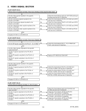
Are the component video signals inputted to the specific output terminal? Yes Replace IC1202 or LCD MODULE. No Yes Are the video signals outputted to the No Pin(67) of No IC1202? Are the Pr signals outputted to the Pin(54) of IC1202? Are the Pb signals inputted to the Pin(19) of CN62, and service it if defective. 7-8 A7144_45TS FLOW CHART NO.24 Picture does not appear...
Are the component video signals inputted to the specific output terminal? Yes Replace IC1202 or LCD MODULE. No Yes Are the video signals outputted to the No Pin(67) of No IC1202? Are the Pr signals outputted to the Pin(54) of IC1202? Are the Pb signals inputted to the Pin(19) of CN62, and service it if defective. 7-8 A7144_45TS FLOW CHART NO.24 Picture does not appear...
Service Manual
Page 28
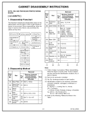
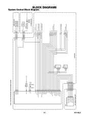
... SWITCH CN1302 3 REMOTE 4 P-ON-H CL1104 3 4 RV1142 REMOTE SENSOR Q1142 LED DRIVE D1142 POWER AL+3.3V(D) IR SENSOR CBA VCOM DTV-ON-H BACKLIGHT-SW P-ON-H VGH-H BACKLIGHT-ADJ TO LCD BLOCK DIAGRAM TO POWER SUPPLY BLOCK DIAGRAM TO LCD BACKLIGHT BLOCK DIAGRAM IF-MUTE INPUT-2 INPUT-0 INPUT-1 S-SW AFT-IN FSC TO IF/VIDEO BLOCK DIAGRAM SCL SDA SCL SDA VOLUME AUDIO-MUTE TO DTV MODULE BLOCK DIAGRAM TO AUDIO BLOCK DIAGRAM BLOCK DIAGRAMS System Control Block Diagram...
... SWITCH CN1302 3 REMOTE 4 P-ON-H CL1104 3 4 RV1142 REMOTE SENSOR Q1142 LED DRIVE D1142 POWER AL+3.3V(D) IR SENSOR CBA VCOM DTV-ON-H BACKLIGHT-SW P-ON-H VGH-H BACKLIGHT-ADJ TO LCD BLOCK DIAGRAM TO POWER SUPPLY BLOCK DIAGRAM TO LCD BACKLIGHT BLOCK DIAGRAM IF-MUTE INPUT-2 INPUT-0 INPUT-1 S-SW AFT-IN FSC TO IF/VIDEO BLOCK DIAGRAM SCL SDA SCL SDA VOLUME AUDIO-MUTE TO DTV MODULE BLOCK DIAGRAM TO AUDIO BLOCK DIAGRAM BLOCK DIAGRAMS System Control Block Diagram...
Service Manual
Page 33
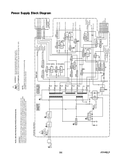
... some components in the power supply circuit are not defective before you connect the AC plug to fail. 4A/125V CAUTION ! : For continued protection against risk of fire, replace only with same type 4 A, 125V fuse. NOTE: The voltage for parts in hot circuit is used in this unit. Q909 SW+2.5V D924 SHUNT REG. CAUTION ! Fixed voltage (or Auto voltage selectable) power supply...
... some components in the power supply circuit are not defective before you connect the AC plug to fail. 4A/125V CAUTION ! : For continued protection against risk of fire, replace only with same type 4 A, 125V fuse. NOTE: The voltage for parts in hot circuit is used in this unit. Q909 SW+2.5V D924 SHUNT REG. CAUTION ! Fixed voltage (or Auto voltage selectable) power supply...
Service Manual
Page 35
... identified in ohms (K=103, M=106). 3. The use the part number shown on these components, read the parts list in this manual and its supplements; All resistance values are identified by using replacement components rated for ordering. Replacement parts that do not have these drawings were prepared. 2. Note: 1. The correct part number is shown in the schematic diagram and the parts list. Resistor wattages are DC voltages unless otherwise...
... identified in ohms (K=103, M=106). 3. The use the part number shown on these components, read the parts list in this manual and its supplements; All resistance values are identified by using replacement components rated for ordering. Replacement parts that do not have these drawings were prepared. 2. Note: 1. The correct part number is shown in the schematic diagram and the parts list. Resistor wattages are DC voltages unless otherwise...
Service Manual
Page 36
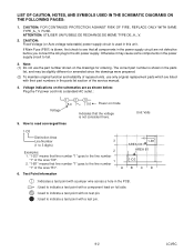
... AGAINST RISK OF FIRE, REPLACE ONLY WITH SAME TYPE_A,_V FUSE. LIST OF CAUTION, NOTES, AND SYMBOLS USED IN THE SCHEMATIC DIAGRAMS ON THE FOLLOWING PAGES: 1. CAUTION: Fixed Voltage (or Auto voltage selectable) power supply circuit is shown in the parts list, and may cause some components in the power supply circuit are listed with no test pin. : Used to the line number 1-D3 "1" of the area...
... AGAINST RISK OF FIRE, REPLACE ONLY WITH SAME TYPE_A,_V FUSE. LIST OF CAUTION, NOTES, AND SYMBOLS USED IN THE SCHEMATIC DIAGRAMS ON THE FOLLOWING PAGES: 1. CAUTION: Fixed Voltage (or Auto voltage selectable) power supply circuit is shown in the parts list, and may cause some components in the power supply circuit are listed with no test pin. : Used to the line number 1-D3 "1" of the area...
Service Manual
Page 46
...replace only with same type 4 A, 125V fuse. Also, in order to have the ability to increase the input slowly,when troubleshooting this unit. ATTENTION : Utiliser un fusible de rechange de même type... The voltage for parts in the power supply circuit are not defective before you connect the AC plug to fail. Fixed voltage (or Auto voltage selectable) power supply circuit is measured using hot GND as ... power supply circuit, an isolation transformer must be used in the power supply circuit to the AC power supply. Otherwise it may cause some components in this type power supply circuit...
...replace only with same type 4 A, 125V fuse. Also, in order to have the ability to increase the input slowly,when troubleshooting this unit. ATTENTION : Utiliser un fusible de rechange de même type... The voltage for parts in the power supply circuit are not defective before you connect the AC plug to fail. Fixed voltage (or Auto voltage selectable) power supply circuit is measured using hot GND as ... power supply circuit, an isolation transformer must be used in the power supply circuit to the AC power supply. Otherwise it may cause some components in this type power supply circuit...
Service Manual
Page 47
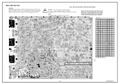
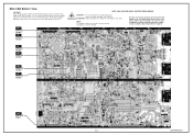
... the power supply circuit are not defective before you connect the AC plug to see that all components in the power supply circuit, an isolation transformer must be used in hot circuit is required. Because a hot chassis ground is blown , check to the AC power supply. Main CBA Bottom View CAUTION ! Also, in the power supply circuit to increase the input slowly,when troubleshooting this...
... the power supply circuit are not defective before you connect the AC plug to see that all components in the power supply circuit, an isolation transformer must be used in hot circuit is required. Because a hot chassis ground is blown , check to the AC power supply. Main CBA Bottom View CAUTION ! Also, in the power supply circuit to increase the input slowly,when troubleshooting this...
Service Manual
Page 50
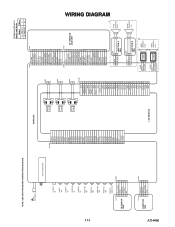
AC601 AC CORD TU61 TUNER UNIT S-VIDEO IN VIDEO -IN1 VIDEO-Y IN VIDEO-Pb IN VIDEO-Pr IN AUDIO(R) -IN1 AUDIO(L) -IN1 AUDIO(R) -IN2 AUDIO(L) -IN2 DIGITAL AUDIO-OUT CL1104 1 2 IR SENSOR 3 CBA 4 5 AL+3.3V(D) GND REMOTE P-ON-H NU CN1302 1 2 3 4 5 CN1201 1 ER [5] 2 ER [4] 3 ER [3] 4 ER [2] 5 ER [1] 6 ER [0] 7 GND 8 CLKL 9 GND 10 OB...of Models and Marks Model Mark LC-20AV7U A LC-20SH7U B CN61 CN101 1 D-GND 1 2 DTV-SPDIF 2 3 DTV-ON+5V 3 4 TU-SCL 4 5 TU-SDA 5 6 D-GND 6 7 DTV-S-SREQ 7 8 DTV-S-SCLK 8 9 DTV-S-SIN 9 10 DTV-S-SOUT 10 11 D-GND 11 12 DTV-S-RESET 12 ...
AC601 AC CORD TU61 TUNER UNIT S-VIDEO IN VIDEO -IN1 VIDEO-Y IN VIDEO-Pb IN VIDEO-Pr IN AUDIO(R) -IN1 AUDIO(L) -IN1 AUDIO(R) -IN2 AUDIO(L) -IN2 DIGITAL AUDIO-OUT CL1104 1 2 IR SENSOR 3 CBA 4 5 AL+3.3V(D) GND REMOTE P-ON-H NU CN1302 1 2 3 4 5 CN1201 1 ER [5] 2 ER [4] 3 ER [3] 4 ER [2] 5 ER [1] 6 ER [0] 7 GND 8 CLKL 9 GND 10 OB...of Models and Marks Model Mark LC-20AV7U A LC-20SH7U B CN61 CN101 1 D-GND 1 2 DTV-SPDIF 2 3 DTV-ON+5V 3 4 TU-SCL 4 5 TU-SDA 5 6 D-GND 6 7 DTV-S-SREQ 7 8 DTV-S-SCLK 8 9 DTV-S-SIN 9 10 DTV-S-SOUT 10 11 D-GND 11 12 DTV-S-RESET 12 ...
Service Manual
Page 53
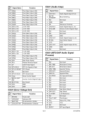
... DTV-S-RESET DTV Reset 154 NU Not Used 155 DTV-S-SCLK DTV Serial Clock 156 Clear Panel Control Signal 157 BACKLIGHTSW Inverter Control Signal Output 158 BOOT-SEL Boot Select 159 VSS GND 160 VSS GND IC601 (Error Voltage Det) Pin No. Signal Name Function 1 CH1 IN A Audio Signal Intput (R ch) 2 MUTE/ STANDBY Mute Switching 3 NU Not Used 4 GND GND 5 RF Reference Terminal 6 CH2 IN A Audio Signal Intput (L ch) 7 VOLUME Volume Control Signal...
... DTV-S-RESET DTV Reset 154 NU Not Used 155 DTV-S-SCLK DTV Serial Clock 156 Clear Panel Control Signal 157 BACKLIGHTSW Inverter Control Signal Output 158 BOOT-SEL Boot Select 159 VSS GND 160 VSS GND IC601 (Error Voltage Det) Pin No. Signal Name Function 1 CH1 IN A Audio Signal Intput (R ch) 2 MUTE/ STANDBY Mute Switching 3 NU Not Used 4 GND GND 5 RF Reference Terminal 6 CH2 IN A Audio Signal Intput (L ch) 7 VOLUME Volume Control Signal...
Service Manual
Page 60
... LCD MODULE LC5 20INCH SPEAKER S0407F10 SPEAKER MAGNETIC S0306N01 SPEAKER S0407F10 SPEAKER MAGNETIC S0306N01 CARTON L7144UH CARTON A7145UH STYROFOAM TOP L7144UH STYROFOAM TOP A7145UH STYROFOAM BOTTOM L7144UH STYROFOAM BOTTOM A7145UH SET BAG L0301UB BARCODE LABEL A7121UH PROTECTION SHEET A7144UH PROTECTION SHEET SIDE A7144UH PROTECTION SHEET SIDE A7145UH STAND HOLD PAD A7144UH BAG POLYETHYLENE 235X365XT0.03 OWNERS MANUAL L7144UH OWNERS MANUAL A7145UH REMOTE CONTROL...
... LCD MODULE LC5 20INCH SPEAKER S0407F10 SPEAKER MAGNETIC S0306N01 SPEAKER S0407F10 SPEAKER MAGNETIC S0306N01 CARTON L7144UH CARTON A7145UH STYROFOAM TOP L7144UH STYROFOAM TOP A7145UH STYROFOAM BOTTOM L7144UH STYROFOAM BOTTOM A7145UH SET BAG L0301UB BARCODE LABEL A7121UH PROTECTION SHEET A7144UH PROTECTION SHEET SIDE A7144UH PROTECTION SHEET SIDE A7145UH STAND HOLD PAD A7144UH BAG POLYETHYLENE 235X365XT0.03 OWNERS MANUAL L7144UH OWNERS MANUAL A7145UH REMOTE CONTROL...
Service Manual
Page 74
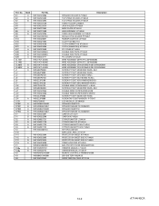
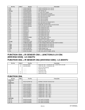
... JACK AV-4B-55H RCA JACK AV-4B-56H RCA JACK AV-4B-57H RCA JACK WHITE AV-4B-58H WHITE RCA JACK AV-4A-57H RED MINIATURE JACK(PB FREE) CKX-035-318AZ4 JACK RCA PCB S AV-4B-70HH PCB JUMPER D0.6-P5.5 PCB JUMPER D0.6-... SCREW B-TIGHT D3X8 BIND HEAD+ SURGE ABSORBER 470V+-10PER FILTER CERAMIC BAND PASS SAFHS45M7VAJZ00B05 TRANS INVERTER ETJV27ZK27AC TRANS INVERTER ETJV27ZK27AC TRANS INVERTER ETJV27ZK27AC TRANS POWER 7709 TUNER UNIT ENV56M07D8F XTAL OSCILLATOR 27.00MHz 15PPM FUNCTION CBA + IR SENSOR CBA + JUNCTION-A & B CBA [9HS1ESA14395] : LC-20AV7U FUNCTION CBA + IR SENSOR CBA [9HS1ESA14399] : LC-20SH7U...
... JACK AV-4B-55H RCA JACK AV-4B-56H RCA JACK AV-4B-57H RCA JACK WHITE AV-4B-58H WHITE RCA JACK AV-4A-57H RED MINIATURE JACK(PB FREE) CKX-035-318AZ4 JACK RCA PCB S AV-4B-70HH PCB JUMPER D0.6-P5.5 PCB JUMPER D0.6-... SCREW B-TIGHT D3X8 BIND HEAD+ SURGE ABSORBER 470V+-10PER FILTER CERAMIC BAND PASS SAFHS45M7VAJZ00B05 TRANS INVERTER ETJV27ZK27AC TRANS INVERTER ETJV27ZK27AC TRANS INVERTER ETJV27ZK27AC TRANS POWER 7709 TUNER UNIT ENV56M07D8F XTAL OSCILLATOR 27.00MHz 15PPM FUNCTION CBA + IR SENSOR CBA + JUNCTION-A & B CBA [9HS1ESA14395] : LC-20AV7U FUNCTION CBA + IR SENSOR CBA [9HS1ESA14399] : LC-20SH7U...


