
Service Manual
Page 2
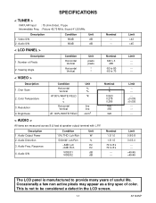
... -6dB: Rch Hz VIDEO1 dB VIDEO2 dB Nominal 1.0/1.0 1.5/1.5 70 to 8 k 70 to provide many years of color. Audio Freq. Limit >43 >45 Limit --------- Audio Output Power 2. SPECIFICATIONS < TUNER > VHF/UHF Input : 75 ohm Unbal., F type Intermediate Freq. : Picture 45.75 MHz, Sound 41.25 MHz Description 1. Brightness Condition Horizontal Vertical AT...
... -6dB: Rch Hz VIDEO1 dB VIDEO2 dB Nominal 1.0/1.0 1.5/1.5 70 to 8 k 70 to provide many years of color. Audio Freq. Limit >43 >45 Limit --------- Audio Output Power 2. SPECIFICATIONS < TUNER > VHF/UHF Input : 75 ohm Unbal., F type Intermediate Freq. : Picture 45.75 MHz, Sound 41.25 MHz Description 1. Brightness Condition Horizontal Vertical AT...
Service Manual
Page 5
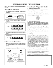
... a dedicated soldering bit, if you may cause damage or accident due to avoid a short circuit. 3-1 LCV_NOTE However, Since the land may be peeled off the power of the soldering bit, it with lead-free solder. Make sure to first disconnect the AC cord. 2. Circuit Board Indications a. Clean the bit after every...
... a dedicated soldering bit, if you may cause damage or accident due to avoid a short circuit. 3-1 LCV_NOTE However, Since the land may be peeled off the power of the soldering bit, it with lead-free solder. Make sure to first disconnect the AC cord. 2. Circuit Board Indications a. Clean the bit after every...
Service Manual
Page 14
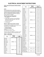
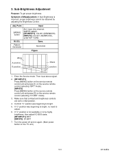
... PWB MEANS PRINTED WIRING BOARD. Also, do not attempt these adjustments unless the proper equipment is important to enter the service mode: Press [MENU] and [POWER] buttons on the remote control) [MENU] → [3] [MENU] → [4] [MENU] → [5] [MENU] → [6] [MENU] → [7] [VOL -] → [1] [VOL -] → [3] Data Value 122 179 80 110...
... PWB MEANS PRINTED WIRING BOARD. Also, do not attempt these adjustments unless the proper equipment is important to enter the service mode: Press [MENU] and [POWER] buttons on the remote control) [MENU] → [3] [MENU] → [4] [MENU] → [5] [MENU] → [6] [MENU] → [7] [VOL -] → [1] [VOL -] → [3] Data Value 122 179 80 110...
Service Manual
Page 15
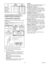
... adjust as shown above. EQ. Initial Setting." [RF/INPUT1]----(APL 20%) Press [3] button to select "C-DB(C/D2)" for Blue adjustment. Turn the power off and on again. (Main power button on the LCD-Panel surface after zero point calibration as a preparation. 2. Press [VOL -] button on the remote control unit and select "C/D1...
... adjust as shown above. EQ. Initial Setting." [RF/INPUT1]----(APL 20%) Press [3] button to select "C-DB(C/D2)" for Blue adjustment. Turn the power off and on again. (Main power button on the LCD-Panel surface after zero point calibration as a preparation. 2. Press [VOL -] button on the remote control unit and select "C/D1...
Service Manual
Page 16
... are set to bright. 5. Confirm "C" position was beginning to bright, no need to be obtained by adjusting the Brightness Control. 3. EQ. Turn the power off and on again. (Main power button on the service remote control (selecting "D1-BRT" mode). 3. Then input above signal. 2. [RF/INPUT1] Press [MENU] button on the service...
... are set to bright. 5. Confirm "C" position was beginning to bright, no need to be obtained by adjusting the Brightness Control. 3. EQ. Turn the power off and on again. (Main power button on the service remote control (selecting "D1-BRT" mode). 3. Then input above signal. 2. [RF/INPUT1] Press [MENU] button on the service...

Service Manual
Page 17
Confirm "FF" indication on the TV unit simultaneously in the standby mode. 2. To enter the service mode, press [MENU] and [POWER] buttons on the upper right of the screen. 6-1 A7144INT To initialize the LCD television, press [DISPLAY] button on the remote control unit. 3. HOW TO INITIALIZE THE LCD TELEVISION 1.
Confirm "FF" indication on the TV unit simultaneously in the standby mode. 2. To enter the service mode, press [MENU] and [POWER] buttons on the upper right of the screen. 6-1 A7144INT To initialize the LCD television, press [DISPLAY] button on the remote control unit. 3. HOW TO INITIALIZE THE LCD TELEVISION 1.
Service Manual
Page 18
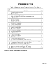
... output voltage fluctuates. 7-2 4 When buzz sound can be heard in the vicinity of Contents for the Troubleshooting Flow Charts Flow Chart No. TROUBLESHOOTING Table of power circuit. 7-2 5 +35V is not output. 7-2 6 VT+33V is not output. 7-3 7 INV+22V is not output. 7-3 8 DTV-ON+3.3V is not output. 7-3 9 DTV-ON+2.5V is...
... output voltage fluctuates. 7-2 4 When buzz sound can be heard in the vicinity of Contents for the Troubleshooting Flow Charts Flow Chart No. TROUBLESHOOTING Table of power circuit. 7-2 5 +35V is not output. 7-2 6 VT+33V is not output. 7-3 7 INV+22V is not output. 7-3 8 DTV-ON+3.3V is not output. 7-3 9 DTV-ON+2.5V is...

Service Manual
Page 19
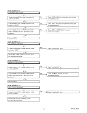
... service it if defective. Is approximately 35V voltage supplied to the cathode of power circuit. Yes Is normal state restored when once unplugged No power cord is not output. After servicing, replace the fuse. POWER SUPPLY SECTION FLOW CHART NO.1 The power cannot be heard in each rectifying circuit of secondary side, and service...
... service it if defective. Is approximately 35V voltage supplied to the cathode of power circuit. Yes Is normal state restored when once unplugged No power cord is not output. After servicing, replace the fuse. POWER SUPPLY SECTION FLOW CHART NO.1 The power cannot be heard in each rectifying circuit of secondary side, and service...
Service Manual
Page 21
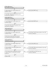
...-H line, and service it if defective. No Is the voltage of base on Q905 lower than the voltage of emitter on Q910 when turning the power on ? FLOW CHART NO.12 PANEL+3.3V is not output. Is approximately 3.3V voltage supplied to the cathode of emitter on Q905 when turning the... power on ? FLOW CHART NO.13 AL+1.2V(D) is not output. Yes Replace Q910. No See FLOW CHART No.11 7-4 A7144_45TS FLOW CHART NO.11 AL+3....
...-H line, and service it if defective. No Is the voltage of base on Q905 lower than the voltage of emitter on Q910 when turning the power on ? FLOW CHART NO.12 PANEL+3.3V is not output. Is approximately 3.3V voltage supplied to the cathode of emitter on Q905 when turning the... power on ? FLOW CHART NO.13 AL+1.2V(D) is not output. Yes Replace Q910. No See FLOW CHART No.11 7-4 A7144_45TS FLOW CHART NO.11 AL+3....
Service Manual
Page 22
... than the No voltage of Q923? Yes Replace Q923. Is approximately 12V voltage supplied to the Yes collector of emitter on Q923 when turning the power on the loaded circuit and service it if defective. See FLOW CHART No.16 Check Q918, D940 and their periphery circuit, and service it if...
... than the No voltage of Q923? Yes Replace Q923. Is approximately 12V voltage supplied to the Yes collector of emitter on Q923 when turning the power on the loaded circuit and service it if defective. See FLOW CHART No.16 Check Q918, D940 and their periphery circuit, and service it if...
Service Manual
Page 28
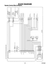
... MAIN CBA CN1301 1 KEY-IN-2 2 KEY-IN-1 CL1107 1 2 FUNCTION CBA KEY SWITCH KEY SWITCH CN1302 3 REMOTE 4 P-ON-H CL1104 3 4 RV1142 REMOTE SENSOR Q1142 LED DRIVE D1142 POWER AL+3.3V(D) IR SENSOR CBA VCOM DTV-ON-H BACKLIGHT-SW P-ON-H VGH-H BACKLIGHT-ADJ TO LCD BLOCK DIAGRAM TO... POWER SUPPLY BLOCK DIAGRAM TO LCD BACKLIGHT BLOCK DIAGRAM IF-MUTE INPUT-2 INPUT-0 INPUT-1 S-SW AFT-IN FSC TO IF/VIDEO BLOCK DIAGRAM SCL SDA SCL ...
... MAIN CBA CN1301 1 KEY-IN-2 2 KEY-IN-1 CL1107 1 2 FUNCTION CBA KEY SWITCH KEY SWITCH CN1302 3 REMOTE 4 P-ON-H CL1104 3 4 RV1142 REMOTE SENSOR Q1142 LED DRIVE D1142 POWER AL+3.3V(D) IR SENSOR CBA VCOM DTV-ON-H BACKLIGHT-SW P-ON-H VGH-H BACKLIGHT-ADJ TO LCD BLOCK DIAGRAM TO... POWER SUPPLY BLOCK DIAGRAM TO LCD BACKLIGHT BLOCK DIAGRAM IF-MUTE INPUT-2 INPUT-0 INPUT-1 S-SW AFT-IN FSC TO IF/VIDEO BLOCK DIAGRAM SCL SDA SCL ...
Service Manual
Page 33
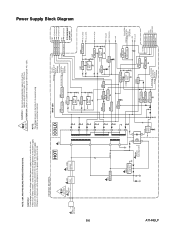
... SWITCHING Q923 SW+12V Q1002 SWITCHING Q1001 SWITCHING Q916 SWITCHING Q907 SW+5V Q918 SW+9V D916 SHUNT REG. Fixed voltage (or Auto voltage selectable) power supply circuit is measured using hot GND as a common terminal. 8-6 AC601 AC CORD HOT CIRCUIT. If Main Fuse (F601) is blown , check to... see that all components in the power supply circuit to the AC power supply. BE CAREFUL. 4A/125V F601 4A/125V L601 LINE FILTER HOT D605 - Q902 SW+3.3V D920 SHUNT REG. Q1005 SW+25V Q1004...
... SWITCHING Q923 SW+12V Q1002 SWITCHING Q1001 SWITCHING Q916 SWITCHING Q907 SW+5V Q918 SW+9V D916 SHUNT REG. Fixed voltage (or Auto voltage selectable) power supply circuit is measured using hot GND as a common terminal. 8-6 AC601 AC CORD HOT CIRCUIT. If Main Fuse (F601) is blown , check to... see that all components in the power supply circuit to the AC power supply. BE CAREFUL. 4A/125V F601 4A/125V L601 LINE FILTER HOT D605 - Q902 SW+3.3V D920 SHUNT REG. Q1005 SW+25V Q1004...

Service Manual
Page 34
TO POWER SUPPLY BLOCK DIAGRAM INV+22V Q401 SW+22V Q407 SWITCHING TO SYSTEM CONTROL BLOCK DIAGRAM BACKLIGHT-ADJ Q405 SWITCHING Q406 +10V REG. A7144BLLB 8-7 NOTE: CBA ...
TO POWER SUPPLY BLOCK DIAGRAM INV+22V Q401 SW+22V Q407 SWITCHING TO SYSTEM CONTROL BLOCK DIAGRAM BACKLIGHT-ADJ Q405 SWITCHING Q406 +10V REG. A7144BLLB 8-7 NOTE: CBA ...
Service Manual
Page 36
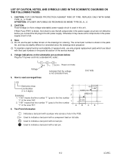
... : Indicates a test point with a jumper wire across a hole in the PCB. : Used to indicate a test point with their part numbers in the power supply circuit are listed with a test pin. 9-2 LCVSC ATTENTION: UTILISER UN FUSIBLE DE RECHANGE DE MEME TYPE DE_A,_V. 2. Otherwise it may be slightly different... is shown in the parts list, and may cause some components in this unit. If Main Fuse (F601) is blown, first check to the AC power supply. ABCD 6. "1-B1" means that line number "1" goes to 3 digits) 3 1-B1 AREA D3 Examples: 2 AREA B1 1. CAUTION: FOR CONTINUED PROTECTION ...
... : Indicates a test point with a jumper wire across a hole in the PCB. : Used to indicate a test point with their part numbers in the power supply circuit are listed with a test pin. 9-2 LCVSC ATTENTION: UTILISER UN FUSIBLE DE RECHANGE DE MEME TYPE DE_A,_V. 2. Otherwise it may be slightly different... is shown in the parts list, and may cause some components in this unit. If Main Fuse (F601) is blown, first check to the AC power supply. ABCD 6. "1-B1" means that line number "1" goes to 3 digits) 3 1-B1 AREA D3 Examples: 2 AREA B1 1. CAUTION: FOR CONTINUED PROTECTION ...
Service Manual
Page 41
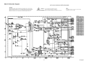
... de même type de 4A, 125V. NOTE: The voltage for parts in hot circuit is blown , check to see that all components in the power supply circuit are not defective before you connect the AC plug to fail. Fixed voltage (or Auto voltage selectable...) power supply circuit is used in the power supply circuit to the AC power supply. MAIN 5/5 Ref No. NOTE: CBA AND PWB MEANS PRINTED WIRING BOARD. 4A/125V CAUTION ! : For continued protection against risk of...
... de même type de 4A, 125V. NOTE: The voltage for parts in hot circuit is blown , check to see that all components in the power supply circuit are not defective before you connect the AC plug to fail. Fixed voltage (or Auto voltage selectable...) power supply circuit is used in the power supply circuit to the AC power supply. MAIN 5/5 Ref No. NOTE: CBA AND PWB MEANS PRINTED WIRING BOARD. 4A/125V CAUTION ! : For continued protection against risk of...
Service Manual
Page 46
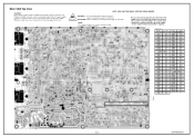
.... 4A/125V CAUTION ! : For continued protection against risk of fire, replace only with same type 4 A, 125V fuse. Also, in the power supply circuit are not defective before you connect the AC plug to fail. Position ICS IC31 A-3 IC61 A-3 IC601 C-5 IC801 C-5 IC851 B-3 IC852...Q462 F-4 Q463 F-3 Q464 F-4 Q601 D-5 Q603 D-5 Q707 B-2 Q708 B-2 Q709 B-2 Ref No. NOTE: The voltage for parts in the power supply circuit to the AC power supply. MAIN CBA Ref No. ATTENTION : Utiliser un fusible de rechange de même type de 4A, 125V. Fixed voltage (or ...
.... 4A/125V CAUTION ! : For continued protection against risk of fire, replace only with same type 4 A, 125V fuse. Also, in the power supply circuit are not defective before you connect the AC plug to fail. Position ICS IC31 A-3 IC61 A-3 IC601 C-5 IC801 C-5 IC851 B-3 IC852...Q462 F-4 Q463 F-3 Q464 F-4 Q601 D-5 Q603 D-5 Q707 B-2 Q708 B-2 Q709 B-2 Ref No. NOTE: The voltage for parts in the power supply circuit to the AC power supply. MAIN CBA Ref No. ATTENTION : Utiliser un fusible de rechange de même type de 4A, 125V. Fixed voltage (or ...
Service Manual
Page 47
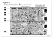
.... ATTENTION : Utiliser un fusible de rechange de même type de 4A, 125V. Also, in this type power supply circuit, a variable isolation transformer is blown , check to see that all components in the power supply circuit to fail. WF4 PIN 75 OF IC1202 WF2 PIN 76 OF IC1202 NOTE: CBA AND PWB... PIN 71 OF IC1202 WF7 PIN 14 OF IC801 9-13 BA7140F01013-1 If Main Fuse (F601) is required. Otherwise it may cause some components in the power supply circuit are not defective before you connect the AC plug to increase the input slowly,when troubleshooting this unit.
.... ATTENTION : Utiliser un fusible de rechange de même type de 4A, 125V. Also, in this type power supply circuit, a variable isolation transformer is blown , check to see that all components in the power supply circuit to fail. WF4 PIN 75 OF IC1202 WF2 PIN 76 OF IC1202 NOTE: CBA AND PWB... PIN 71 OF IC1202 WF7 PIN 14 OF IC801 9-13 BA7140F01013-1 If Main Fuse (F601) is required. Otherwise it may cause some components in the power supply circuit are not defective before you connect the AC plug to increase the input slowly,when troubleshooting this unit.
Service Manual
Page 51
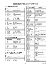
... Amp Feed Back IC61, IC1205 (Memory) Pin No. Signal Name Function 4 KEY-IN-2 Key Input 2 5 AFT-IN AFT Voltage Input 6 PROTECT-1 Power Supply Protection 1 7 PROTECT-2 Power Supply Protection 2 8 PROTECT-4 Power Supply Protection 4 9 ADIN6 Reference Terminal 10 VSS GND 11 NU Not Used 12 NU Not Used 13 NU Not Used 14 NU...24 VDD+1.2V +1.2V VDD 25 VDD+1.2V +1.2V VDD 26 VGH-H VGH Signal at High 27 REMOTE Remote Control Signal Input 28 P-ON-H Power On Signal at High 29 BUS-OPEN Chip select 30 SCL Serial Clock 31 SDA Serial Data 32 NU Not Used 33 NU Not Used...
... Amp Feed Back IC61, IC1205 (Memory) Pin No. Signal Name Function 4 KEY-IN-2 Key Input 2 5 AFT-IN AFT Voltage Input 6 PROTECT-1 Power Supply Protection 1 7 PROTECT-2 Power Supply Protection 2 8 PROTECT-4 Power Supply Protection 4 9 ADIN6 Reference Terminal 10 VSS GND 11 NU Not Used 12 NU Not Used 13 NU Not Used 14 NU...24 VDD+1.2V +1.2V VDD 25 VDD+1.2V +1.2V VDD 26 VGH-H VGH Signal at High 27 REMOTE Remote Control Signal Input 28 P-ON-H Power On Signal at High 29 BUS-OPEN Chip select 30 SCL Serial Clock 31 SDA Serial Data 32 NU Not Used 33 NU Not Used...

Service Manual
Page 67
... J 100 Ω PCB JUMPER D0.6-P5.0 CARBON RES. 1/4W J 120 Ω INDUCTOR 1.0µH-J-26T INDUCTOR 1.0µH-J-26T INDUCTOR 1.0µH-J-26T INDUCTOR 1.0µH-J-26T NPN TRANSISTOR POWER 2SC4881F HFE MAX320 TRANSISTOR 2SA950-Y(TE2 F T) TRANSISTOR 2SC2785(F) TRANSISTOR 2SC2785(F) TRANSISTOR 2SA1175(F) TRANSISTOR 2SC2120-Y(TE2 F T) TRANSISTOR 2SC2785(F) FET MOS SMD HAT2215R01-EL-E 15-7 A7144/45EL...
... J 100 Ω PCB JUMPER D0.6-P5.0 CARBON RES. 1/4W J 120 Ω INDUCTOR 1.0µH-J-26T INDUCTOR 1.0µH-J-26T INDUCTOR 1.0µH-J-26T INDUCTOR 1.0µH-J-26T NPN TRANSISTOR POWER 2SC4881F HFE MAX320 TRANSISTOR 2SA950-Y(TE2 F T) TRANSISTOR 2SC2785(F) TRANSISTOR 2SC2785(F) TRANSISTOR 2SA1175(F) TRANSISTOR 2SC2120-Y(TE2 F T) TRANSISTOR 2SC2785(F) FET MOS SMD HAT2215R01-EL-E 15-7 A7144/45EL...
Service Manual
Page 74
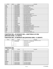
... CERAMIC BAND PASS SAFHS45M7VAJZ00B05 TRANS INVERTER ETJV27ZK27AC TRANS INVERTER ETJV27ZK27AC TRANS INVERTER ETJV27ZK27AC TRANS POWER 7709 TUNER UNIT ENV56M07D8F XTAL OSCILLATOR 27.00MHz 15PPM FUNCTION CBA + IR SENSOR CBA + JUNCTION-A & B CBA [9HS1ESA14395] : LC-20AV7U FUNCTION CBA + IR SENSOR CBA [9HS1ESA14399] : LC-20SH7U Ref. Mark A B Part No. 9HS1ESA14395 9HS1ESA14399 A ---------A ---------- No. Ref. FH601 FH602 GP642# JK701...
... CERAMIC BAND PASS SAFHS45M7VAJZ00B05 TRANS INVERTER ETJV27ZK27AC TRANS INVERTER ETJV27ZK27AC TRANS INVERTER ETJV27ZK27AC TRANS POWER 7709 TUNER UNIT ENV56M07D8F XTAL OSCILLATOR 27.00MHz 15PPM FUNCTION CBA + IR SENSOR CBA + JUNCTION-A & B CBA [9HS1ESA14395] : LC-20AV7U FUNCTION CBA + IR SENSOR CBA [9HS1ESA14399] : LC-20SH7U Ref. Mark A B Part No. 9HS1ESA14395 9HS1ESA14399 A ---------A ---------- No. Ref. FH601 FH602 GP642# JK701...


