
Service Manual
Page 18
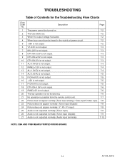
... the remote control unit. 7-7 22 Picture does not appear normally. (Tuner input (Analog) / Video input/S-Video input) 7-8 23 Picture does not appear normally. (Tuner input (Digital)) 7-8 24 Picture does not appear normally. (Y / Pb / Pr input) 7-8 25 Audio is not outputted normally. (Tuner input) 7-9 26 Audio is not outputted normally. (Tuner input...
... the remote control unit. 7-7 22 Picture does not appear normally. (Tuner input (Analog) / Video input/S-Video input) 7-8 23 Picture does not appear normally. (Tuner input (Digital)) 7-8 24 Picture does not appear normally. (Y / Pb / Pr input) 7-8 25 Audio is not outputted normally. (Tuner input) 7-9 26 Audio is not outputted normally. (Tuner input...
Service Manual
Page 25
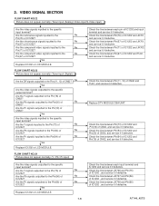
Are the component video signals inputted to the Pins(11, 12) of IC1202? FLOW CHART NO.23 Picture does not appear normally. (Tuner input (Digital)) Are the DIF signals outputted to the No Pin(71) of CN62? No Yes Are the video signals outputted to the specific input terminal? FLOW ...
Are the component video signals inputted to the Pins(11, 12) of IC1202? FLOW CHART NO.23 Picture does not appear normally. (Tuner input (Digital)) Are the DIF signals outputted to the No Pin(71) of CN62? No Yes Are the video signals outputted to the specific input terminal? FLOW ...

Service Manual
Page 26
... the audio (L/R) signals outputted to the No Pins(3, 13) of IC852? AUDIO SIGNAL SECTION FLOW CHART NO.25 Audio is not outputted normally. (Tuner input (Digital)) Are the DIF signals outputted to the Pins(3,13) No of IC852?
... the audio (L/R) signals outputted to the No Pins(3, 13) of IC852? AUDIO SIGNAL SECTION FLOW CHART NO.25 Audio is not outputted normally. (Tuner input (Digital)) Are the DIF signals outputted to the Pins(3,13) No of IC852?
Service Manual
Page 36
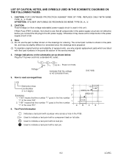
... with a test pin. 9-2 LCVSC Note: (1) Do not use only original replacement parts which are listed with their part numbers in the power supply circuit to 3 digits) 3 1-B1 AREA D3 Examples: 2 AREA B1 1. Voltage indications on the schematics are not defective before you connect the AC plug to the line number 1-D3...
... with a test pin. 9-2 LCVSC Note: (1) Do not use only original replacement parts which are listed with their part numbers in the power supply circuit to 3 digits) 3 1-B1 AREA D3 Examples: 2 AREA B1 1. Voltage indications on the schematics are not defective before you connect the AC plug to the line number 1-D3...
Service Manual
Page 50
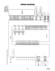
... AC CORD TU61 TUNER UNIT S-VIDEO IN VIDEO -IN1 VIDEO-Y IN VIDEO-Pb IN VIDEO-Pr IN AUDIO(R) -IN1 AUDIO(L) -IN1 AUDIO(R) -IN2 AUDIO(L) -IN2 DIGITAL AUDIO-OUT CL1104 1 2 IR SENSOR 3 CBA 4 5 AL+3.3V(D) GND REMOTE P-ON-H NU CN1302 1 2 3 4 5 CN1201 1 ER [5] 2 ER [4] 3 ER [3] 4 ER [2] 5 ER [1] 6 ER [0] 7 GND 8 ... 17 18 19 20 21 22 23 24 25 26 27 28 29 30 31 32 33 Comparison Chart of Models and Marks Model Mark LC-20AV7U A LC-20SH7U B CN61 CN101 1 D-GND 1 2 DTV-SPDIF 2 3 DTV-ON+5V 3 4 TU-SCL 4 5 TU-SDA 5 6 D-GND 6 7 DTV-S-SREQ 7 8 DTV-S-SCLK 8 9 DTV-S-SIN 9 10...
... AC CORD TU61 TUNER UNIT S-VIDEO IN VIDEO -IN1 VIDEO-Y IN VIDEO-Pb IN VIDEO-Pr IN AUDIO(R) -IN1 AUDIO(L) -IN1 AUDIO(R) -IN2 AUDIO(L) -IN2 DIGITAL AUDIO-OUT CL1104 1 2 IR SENSOR 3 CBA 4 5 AL+3.3V(D) GND REMOTE P-ON-H NU CN1302 1 2 3 4 5 CN1201 1 ER [5] 2 ER [4] 3 ER [3] 4 ER [2] 5 ER [1] 6 ER [0] 7 GND 8 ... 17 18 19 20 21 22 23 24 25 26 27 28 29 30 31 32 33 Comparison Chart of Models and Marks Model Mark LC-20AV7U A LC-20SH7U B CN61 CN101 1 D-GND 1 2 DTV-SPDIF 2 3 DTV-ON+5V 3 4 TU-SCL 4 5 TU-SDA 5 6 D-GND 6 7 DTV-S-SREQ 7 8 DTV-S-SCLK 8 9 DTV-S-SIN 9 10...

