
Service Manual
Page 1
SERVICE MANUAL LCD COLOR TELEVISION LC-20AV7U/LC-20SH7U SERVICE MANUAL S37F3LC20AV7U LCD COLOR TELEVISION MODEL LC-20AV7U MODEL LC-20SH7U In the interests of user-safety (Required by safety regulations in some countries) the set should be restored to its original condition and only parts identical to change without notice. CONTENTS Page SPECIFICATIONS ...1-1 IMPORTANT SAFEGUARDS AND PRECAUTIONS... LIST ...15-1 This document has been published to be used for after sales service only. 1 The contents are subject to those specified be used . MODELS LC-20AV7U/LC-20SH7U
SERVICE MANUAL LCD COLOR TELEVISION LC-20AV7U/LC-20SH7U SERVICE MANUAL S37F3LC20AV7U LCD COLOR TELEVISION MODEL LC-20AV7U MODEL LC-20SH7U In the interests of user-safety (Required by safety regulations in some countries) the set should be restored to its original condition and only parts identical to change without notice. CONTENTS Page SPECIFICATIONS ...1-1 IMPORTANT SAFEGUARDS AND PRECAUTIONS... LIST ...15-1 This document has been published to be used for after sales service only. 1 The contents are subject to those specified be used . MODELS LC-20AV7U/LC-20SH7U
Service Manual
Page 2
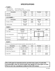
... line cd/m2 Nominal 5 5 10500 0.278 0.286 400 350 320 < AUDIO > All items are measured across 8 Ω load at speaker output terminal with L.P.F. Audio Distortion 3. SPECIFICATIONS < TUNER > VHF/UHF Input : 75 ohm Unbal., F type Intermediate Freq. : Picture 45.75 MHz, Sound 41.25 MHz Description 1. Video S/N 2. Number of Pixels 2. Limit >43...
... line cd/m2 Nominal 5 5 10500 0.278 0.286 400 350 320 < AUDIO > All items are measured across 8 Ω load at speaker output terminal with L.P.F. Audio Distortion 3. SPECIFICATIONS < TUNER > VHF/UHF Input : 75 ohm Unbal., F type Intermediate Freq. : Picture 45.75 MHz, Sound 41.25 MHz Description 1. Video S/N 2. Number of Pixels 2. Limit >43...
Service Manual
Page 3
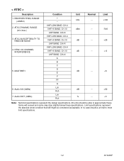
CH.4 VHF HI BAND. CH.41 VHF LOW BAND. RECEIVED FREQ. ATSC DYNAMIC RANGE (min./max.) 3. Audio S/N (0dBfs) 7. CH.4 VHF HI BAND. CH.10 UHF BAND. CH.4 VHF HI BAND. ATSC SUSCEPTIBILITY TO RANDOM NOISE 4. Audio DIST. (0dBfs) Condition + - CH.41 VHF LOW BAND. RANGE (-28dBm) 2. VHF LOW BAND. CH.41 A B C D E F FF G Lch Rch Lch Rch Unit Nominal Limit kHz --- >100 dBm --- -76/0 dB --- -6 dB --- 50 % --- NTSC CO-CHANNEL INTERFERENCE 5. CH.10 UHF BAND. < ATSC > Description 1. MULTIPATH 6. CH.10 UHF BAND.
CH.4 VHF HI BAND. CH.41 VHF LOW BAND. RECEIVED FREQ. ATSC DYNAMIC RANGE (min./max.) 3. Audio S/N (0dBfs) 7. CH.4 VHF HI BAND. CH.10 UHF BAND. CH.4 VHF HI BAND. ATSC SUSCEPTIBILITY TO RANDOM NOISE 4. Audio DIST. (0dBfs) Condition + - CH.41 VHF LOW BAND. RANGE (-28dBm) 2. VHF LOW BAND. CH.41 A B C D E F FF G Lch Rch Lch Rch Unit Nominal Limit kHz --- >100 dBm --- -76/0 dB --- -6 dB --- 50 % --- NTSC CO-CHANNEL INTERFERENCE 5. CH.10 UHF BAND. < ATSC > Description 1. MULTIPATH 6. CH.10 UHF BAND.
Service Manual
Page 15
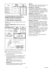
... Setting." [INPUT2]----(APL 20%) Press [3] button to select "DB(C/D1)" for Red adjustment.When "x" value and "y" value are not within specification, adjust "CCOB(C/D2)" or "C-COR(C/D2)". Note: The optical receptor must be set perpendicularly to "1. Spec. Perpendicularity [INPUT2] Enter the Service...278 ± 0.005 y= 0.286 ± 0.005 Figure It carries out in the field. When "x" value and "y" value are not within specification, adjust "DB (C/D1)" or "DR (C/D1)". White Balance Adjustment Purpose: To mix red, green and blue beams correctly for more than 20 minutes...
... Setting." [INPUT2]----(APL 20%) Press [3] button to select "DB(C/D1)" for Red adjustment.When "x" value and "y" value are not within specification, adjust "CCOB(C/D2)" or "C-COR(C/D2)". Note: The optical receptor must be set perpendicularly to "1. Spec. Perpendicularity [INPUT2] Enter the Service...278 ± 0.005 y= 0.286 ± 0.005 Figure It carries out in the field. When "x" value and "y" value are not within specification, adjust "DB (C/D1)" or "DR (C/D1)". White Balance Adjustment Purpose: To mix red, green and blue beams correctly for more than 20 minutes...
Service Manual
Page 25
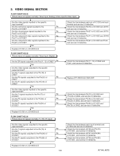
... Y signals outputted to the Pin(73) of IC1202? Are the Y signals inputted to the Pin(18) of IC1202? Are the chrominance signals inputted to the specific input terminal? Yes Are the video signals inputted to the No Pin(57) of CN62? FLOW CHART NO.24 Picture does not appear normally. (Y / Pb... line between Pin(54) of IC1202 and Pin(20) of IC1202 and JK701, and service it if defective. Are the Pr signals outputted to the specific input terminal? Check the line between Pin(57) of CN62, and service it if defective. Are the Pb signals outputted to the Pins(11, 12...
... Y signals outputted to the Pin(73) of IC1202? Are the Y signals inputted to the Pin(18) of IC1202? Are the chrominance signals inputted to the specific input terminal? Yes Are the video signals inputted to the No Pin(57) of CN62? FLOW CHART NO.24 Picture does not appear normally. (Y / Pb... line between Pin(54) of IC1202 and Pin(20) of IC1202 and JK701, and service it if defective. Are the Pr signals outputted to the specific input terminal? Check the line between Pin(57) of CN62, and service it if defective. Are the Pb signals outputted to the Pins(11, 12...

