
Service Manual
Page 6
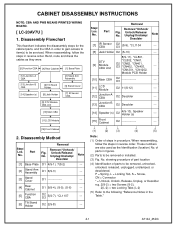
...and the CBA in reverse order. No. No. CABINET DISASSEMBLY INSTRUCTIONS NOTE: CBA AND PWB MEANS PRINTED WIRING BOARD. [ LC-20AV7U ] 1. When reassembling, follow the steps in figures. (2) Parts to be removed, unhooked, unlocked, released, unplugged, ... installed. (3) Fig. showing procedure of part location (4) Identification of parts to be serviced. Unlock/Release/ Unplug/Unclamp/ Note Desolder [1] Base Plate D1 4(S-1), 7(S-2) --- [2] Stand Arm Assembly D1 6(S-3) --- [3] Stand Cover D1 --- [4] Rear Cabinet D1 9(S-4), (S-5), (S-6) ---...
...and the CBA in reverse order. No. No. CABINET DISASSEMBLY INSTRUCTIONS NOTE: CBA AND PWB MEANS PRINTED WIRING BOARD. [ LC-20AV7U ] 1. When reassembling, follow the steps in figures. (2) Parts to be removed, unhooked, unlocked, released, unplugged, ... installed. (3) Fig. showing procedure of part location (4) Identification of parts to be serviced. Unlock/Release/ Unplug/Unclamp/ Note Desolder [1] Base Plate D1 4(S-1), 7(S-2) --- [2] Stand Arm Assembly D1 6(S-3) --- [3] Stand Cover D1 --- [4] Rear Cabinet D1 9(S-4), (S-5), (S-6) ---...

Service Manual
Page 7
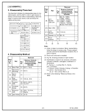
D1 4-2 A7144_45DC [4] Rear Cabinet (S-5) (S-4) (S-4) (S-4) (S-4) (S-6) (S-4) (S-1) [3] Stand Cover [2] Stand Arm Assembly [1] Base Plate (S-3) (S-3) (S-2) (S-2) (S-2) Fig.
D1 4-2 A7144_45DC [4] Rear Cabinet (S-5) (S-4) (S-4) (S-4) (S-4) (S-6) (S-4) (S-1) [3] Stand Cover [2] Stand Arm Assembly [1] Base Plate (S-3) (S-3) (S-2) (S-2) (S-2) Fig.
Service Manual
Page 10
... Cover [10] Main CBA [11] LCD Module [13] Front Cabinet 4. When reassembling, follow the steps in reverse order. No. Unlock/Release/ Unplug/Unclamp/ Note Desolder [1] Base Plate D1 2(S-1), 7(S-2) --- [2] Stand Arm Assembly D1 6(S-3) --- [3] Stand Cover D1 --- [4] Rear Cabinet D1 10(S-4), (S-5) --- [5] Function CBA D2 2(S-6), 3(S-7), D3 *CL1107 --- [6] Tilt Stand Holder D2 2(S-8) --- ... 8(S-11), *CN61, DTV [9] Module CBA Unit *CN62, *CN401, D2 *CN402, *CN403, D3 *CN801, *CN802, *CN1201, *CN1202, --- of parts to be serviced. No. [ LC-20SH7U ] 3.
... Cover [10] Main CBA [11] LCD Module [13] Front Cabinet 4. When reassembling, follow the steps in reverse order. No. Unlock/Release/ Unplug/Unclamp/ Note Desolder [1] Base Plate D1 2(S-1), 7(S-2) --- [2] Stand Arm Assembly D1 6(S-3) --- [3] Stand Cover D1 --- [4] Rear Cabinet D1 10(S-4), (S-5) --- [5] Function CBA D2 2(S-6), 3(S-7), D3 *CL1107 --- [6] Tilt Stand Holder D2 2(S-8) --- ... 8(S-11), *CN61, DTV [9] Module CBA Unit *CN62, *CN401, D2 *CN402, *CN403, D3 *CN801, *CN802, *CN1201, *CN1202, --- of parts to be serviced. No. [ LC-20SH7U ] 3.

Service Manual
Page 11
D1 4-6 A7144_45DC [4] Rear Cabinet (S-4) (S-4) (S-4) (S-5) (S-1) (S-4) [3] Stand Cover [2] Stand Arm Assembly [1] Base Plate (S-3) (S-3) (S-2) (S-2) (S-2) Fig.
D1 4-6 A7144_45DC [4] Rear Cabinet (S-4) (S-4) (S-4) (S-5) (S-1) (S-4) [3] Stand Cover [2] Stand Arm Assembly [1] Base Plate (S-3) (S-3) (S-2) (S-2) (S-2) Fig.
Service Manual
Page 21
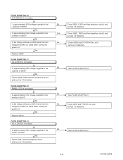
... CHART NO.13 AL+1.2V(D) is not output. No Check Q906 and DTV-ON-H line, and service it if defective. No Is the voltage of base on ? Yes Check IC901 and the periphery circuit, and service it if defective. No See FLOW CHART No.11 7-4 A7144_45TS Is approximately 3.3V voltage supplied... supplied to the cathode of emitter on Q905 when turning the power on Q910 lower than the voltage of D903? Yes Is the voltage of base on ? Yes Check Q907, D922 and their periphery circuit, and service it if defective.
... CHART NO.13 AL+1.2V(D) is not output. No Check Q906 and DTV-ON-H line, and service it if defective. No Is the voltage of base on ? Yes Check IC901 and the periphery circuit, and service it if defective. No See FLOW CHART No.11 7-4 A7144_45TS Is approximately 3.3V voltage supplied... supplied to the cathode of emitter on Q905 when turning the power on Q910 lower than the voltage of D903? Yes Is the voltage of base on ? Yes Check Q907, D922 and their periphery circuit, and service it if defective.
Service Manual
Page 22
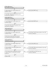
... it if defective. FLOW CHART NO.14 AL+3.3V(A) is not output. FLOW CHART NO.16 +12V is not output. No Is the voltage of base on ?
... it if defective. FLOW CHART NO.14 AL+3.3V(A) is not output. FLOW CHART NO.16 +12V is not output. No Is the voltage of base on ?
Service Manual
Page 60
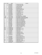
... 9HS1EM424538 9HS0EM408420A 9HS1EMN22182 9HS1EMN22181 9HSREMT32HD004 9HSB0M311MS001 9HS1EM322562 Description SPEAKER HOLDER A7120UH TILT STAND HOLDER A7140UH TILT STAND HOLDER A7145UH STAND HOLDER L2500UA JACK HOLDER A7140UH BASE PLATE A7144UH ARM ASSEMBLY A7140UH STAND ARM ASSEMBLY A7145UH MODULE PCB HOLDER P7150UT RUBBER CUSHION L0170UA CLOTH 10X150XT1.0 CLOTH(10X90XT1.0) A7120UH CLOTH(15X40XT0.5) A7140UH PC...
... 9HS1EM424538 9HS0EM408420A 9HS1EMN22182 9HS1EMN22181 9HSREMT32HD004 9HSB0M311MS001 9HS1EM322562 Description SPEAKER HOLDER A7120UH TILT STAND HOLDER A7140UH TILT STAND HOLDER A7145UH STAND HOLDER L2500UA JACK HOLDER A7140UH BASE PLATE A7144UH ARM ASSEMBLY A7140UH STAND ARM ASSEMBLY A7145UH MODULE PCB HOLDER P7150UT RUBBER CUSHION L0170UA CLOTH 10X150XT1.0 CLOTH(10X90XT1.0) A7120UH CLOTH(15X40XT0.5) A7140UH PC...


