
Service Manual
Page 9
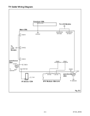
TV Cable Wiring Diagram Main CBA CN401 Function CBA CL1107 CN1301 To LCD Module CN1202 CN1201 To LCD Module CN402 Junction-A CBA CL801 To Speaker CN403 CN801 CN1302 CL1104 IR Sensor CBA CN62 CN61 CN102 CN101 CN802 Junction-B CBA CL802 DTV Module CBA Unit To Speaker Fig. D3 4-4 A7144_45DC
TV Cable Wiring Diagram Main CBA CN401 Function CBA CL1107 CN1301 To LCD Module CN1202 CN1201 To LCD Module CN402 Junction-A CBA CL801 To Speaker CN403 CN801 CN1302 CL1104 IR Sensor CBA CN62 CN61 CN102 CN101 CN802 Junction-B CBA CL802 DTV Module CBA Unit To Speaker Fig. D3 4-4 A7144_45DC
Service Manual
Page 13
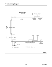
TV Cable Wiring Diagram Main CBA CN401 Function CBA CL1107 CN1301 To LCD Module CN1202 CN1201 To LCD Module CN402 To Speaker CN403 CN801 CN1302 CL1104 IR Sensor CBA CN62 CN61 CN102 CN101 DTV Module CBA Unit CN802 To Speaker Fig. D3 4-8 A7144_45DC
TV Cable Wiring Diagram Main CBA CN401 Function CBA CL1107 CN1301 To LCD Module CN1202 CN1201 To LCD Module CN402 To Speaker CN403 CN801 CN1302 CL1104 IR Sensor CBA CN62 CN61 CN102 CN101 DTV Module CBA Unit CN802 To Speaker Fig. D3 4-8 A7144_45DC
Service Manual
Page 15
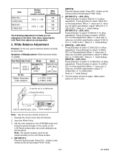
...for Blue adjustment. Initial Setting." [RF/INPUT1]----(APL 20%) Press [3] button to select "DR(C/D1)" for pure white. Only when replacing the LCD Panel then adjust as shown above. Refer to "1. Input the White Purity. 3. Initial Setting." 7. Note: The optical receptor must be set ...button to select "C-DB(C/D2)" for Blue adjustment. Press [VOL -] button on the TV unit.) L = 3 cm INPUT: WHITE 80%, 20% Color Analyzer Note: Use the service remote control unit 1. Press [1] button to the LCD Panel surface. 4. [RF/INPUT1] Enter the Service mode. Operate the unit for Red...
...for Blue adjustment. Initial Setting." [RF/INPUT1]----(APL 20%) Press [3] button to select "DR(C/D1)" for pure white. Only when replacing the LCD Panel then adjust as shown above. Refer to "1. Input the White Purity. 3. Initial Setting." 7. Note: The optical receptor must be set ...button to select "C-DB(C/D2)" for Blue adjustment. Press [VOL -] button on the TV unit.) L = 3 cm INPUT: WHITE 80%, 20% Color Analyzer Note: Use the service remote control unit 1. Press [1] button to the LCD Panel surface. 4. [RF/INPUT1] Enter the Service mode. Operate the unit for Red...
Service Manual
Page 17
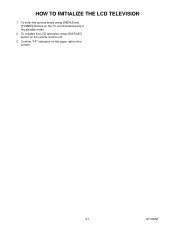
Confirm "FF" indication on the remote control unit. 3. To initialize the LCD television, press [DISPLAY] button on the upper right of the screen. 6-1 A7144INT To enter the service mode, press [MENU] and [POWER] buttons on the TV unit simultaneously in the standby mode. 2. HOW TO INITIALIZE THE LCD TELEVISION 1.
Confirm "FF" indication on the remote control unit. 3. To initialize the LCD television, press [DISPLAY] button on the upper right of the screen. 6-1 A7144INT To enter the service mode, press [MENU] and [POWER] buttons on the TV unit simultaneously in the standby mode. 2. HOW TO INITIALIZE THE LCD TELEVISION 1.
Service Manual
Page 28
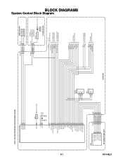
A7144BLS 8-1 NOTE: CBA AND PWB MEANS PRINTED WIRING BOARD. IC1202 (TV MICRO CONTROLLER) KEY-IN-2 4 KEY-IN-1 3 REMOTE 27 RESET 94 XIN 37 XOUT 38 Q917 RESET AL+3.3V(D) X1301 27MHz VCOM 19 DTV-ON-H 152 ... SENSOR Q1142 LED DRIVE D1142 POWER AL+3.3V(D) IR SENSOR CBA VCOM DTV-ON-H BACKLIGHT-SW P-ON-H VGH-H BACKLIGHT-ADJ TO LCD BLOCK DIAGRAM TO POWER SUPPLY BLOCK DIAGRAM TO LCD BACKLIGHT BLOCK DIAGRAM IF-MUTE INPUT-2 INPUT-0 INPUT-1 S-SW AFT-IN FSC TO IF/VIDEO BLOCK DIAGRAM SCL SDA SCL SDA...
A7144BLS 8-1 NOTE: CBA AND PWB MEANS PRINTED WIRING BOARD. IC1202 (TV MICRO CONTROLLER) KEY-IN-2 4 KEY-IN-1 3 REMOTE 27 RESET 94 XIN 37 XOUT 38 Q917 RESET AL+3.3V(D) X1301 27MHz VCOM 19 DTV-ON-H 152 ... SENSOR Q1142 LED DRIVE D1142 POWER AL+3.3V(D) IR SENSOR CBA VCOM DTV-ON-H BACKLIGHT-SW P-ON-H VGH-H BACKLIGHT-ADJ TO LCD BLOCK DIAGRAM TO POWER SUPPLY BLOCK DIAGRAM TO LCD BACKLIGHT BLOCK DIAGRAM IF-MUTE INPUT-2 INPUT-0 INPUT-1 S-SW AFT-IN FSC TO IF/VIDEO BLOCK DIAGRAM SCL SDA SCL SDA...
Service Manual
Page 51
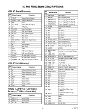
... 0 Input 2 A1 Slave Address 1 Input 3 A2 Slave Address 2 Input 4 GND GND 5 SDA Serial Data 6 SCL Serial Clock 7 WP Write Protect 8 VCC VCC IC1202 (LCD Drive / LCD Signal Process / TV Micro Controller) Pin No. Signal Name Function 1 V-OUT Video Signal Output 2 DEFECT-SW Defect Switching 3 VCC VCC 4 DET-OUT Video Detect Output 5 APC APC...
... 0 Input 2 A1 Slave Address 1 Input 3 A2 Slave Address 2 Input 4 GND GND 5 SDA Serial Data 6 SCL Serial Clock 7 WP Write Protect 8 VCC VCC IC1202 (LCD Drive / LCD Signal Process / TV Micro Controller) Pin No. Signal Name Function 1 V-OUT Video Signal Output 2 DEFECT-SW Defect Switching 3 VCC VCC 4 DET-OUT Video Detect Output 5 APC APC...


