
Service Manual
Page 6
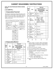
... CBA [14] Speaker (s) [6] Tilt Stand Holder [8] Jack Holder [9] DTV Module CBA Unit [2] Stand Arm Assembly [3] Stand Cover [7] IR Sensor CBA [10] ...Stand Cover D1 --- [4] Rear Cabinet D1 9(S-4), (S-5), (S-6) --- [5] Function CBA D2 D3 5(S-7), *CL1107 --- [6] Tilt Stand Holder D2 2(S-8) --- No. No. No. No. Part Remove/*Unhook/ Fig. Disassembly Method Removal Step/ Remove/*Unhook/ Loc. showing procedure of part location (4) Identification of parts in reverse order. CABINET DISASSEMBLY INSTRUCTIONS NOTE: CBA AND PWB MEANS PRINTED WIRING BOARD. [ LC-20AV7U...
... CBA [14] Speaker (s) [6] Tilt Stand Holder [8] Jack Holder [9] DTV Module CBA Unit [2] Stand Arm Assembly [3] Stand Cover [7] IR Sensor CBA [10] ...Stand Cover D1 --- [4] Rear Cabinet D1 9(S-4), (S-5), (S-6) --- [5] Function CBA D2 D3 5(S-7), *CL1107 --- [6] Tilt Stand Holder D2 2(S-8) --- No. No. No. No. Part Remove/*Unhook/ Fig. Disassembly Method Removal Step/ Remove/*Unhook/ Loc. showing procedure of part location (4) Identification of parts in reverse order. CABINET DISASSEMBLY INSTRUCTIONS NOTE: CBA AND PWB MEANS PRINTED WIRING BOARD. [ LC-20AV7U...

Service Manual
Page 7
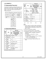
D1 4-2 A7144_45DC [4] Rear Cabinet (S-5) (S-4) (S-4) (S-4) (S-4) (S-6) (S-4) (S-1) [3] Stand Cover [2] Stand Arm Assembly [1] Base Plate (S-3) (S-3) (S-2) (S-2) (S-2) Fig.
D1 4-2 A7144_45DC [4] Rear Cabinet (S-5) (S-4) (S-4) (S-4) (S-4) (S-6) (S-4) (S-1) [3] Stand Cover [2] Stand Arm Assembly [1] Base Plate (S-3) (S-3) (S-2) (S-2) (S-2) Fig.

Service Manual
Page 8
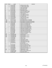
[15] Front Cabinet [13] Junction-B CBA Speaker Holder (S-12) (S-7) [5] Function CBA (S-7) [11] LCD Module (S-12) Desolder [14] Speaker (S-13) (S-12) (S-12) [14] Speaker (S-9) Desolder (S-12) [10] Main CBA [8] Jack (S-12) (S-11) Holder (S-11) [7] IR Sensor CBA Speaker Holder [12] Junction-A CBA (S-13) (S-12) (S-8) (S-11) [6] Tilt Stand Holder (S-10) Module PCB Holder (S-11) (S-11) (S-11) [9] DTV Module CBA Unit Fig. D2 4-3 A7144_45DC
[15] Front Cabinet [13] Junction-B CBA Speaker Holder (S-12) (S-7) [5] Function CBA (S-7) [11] LCD Module (S-12) Desolder [14] Speaker (S-13) (S-12) (S-12) [14] Speaker (S-9) Desolder (S-12) [10] Main CBA [8] Jack (S-12) (S-11) Holder (S-11) [7] IR Sensor CBA Speaker Holder [12] Junction-A CBA (S-13) (S-12) (S-8) (S-11) [6] Tilt Stand Holder (S-10) Module PCB Holder (S-11) (S-11) (S-11) [9] DTV Module CBA Unit Fig. D2 4-3 A7144_45DC
Service Manual
Page 10
.... These numbers are also used as they were. [5] Function CBA [4] Rear Cabinet [1] Base Plate [12] Speaker (s) [7] IR Sensor CBA [6] Tilt Stand Holder [8] Jack Holder [9] DTV Module CBA Unit [2] Stand Arm Assembly [3] Stand Cover [10] Main CBA [11] LCD Module [13] Front Cabinet 4. Disassembly Flowchart This flowchart indicates the disassembly steps for the cabinet... to item(s) to the following "Reference Notes in procedure. Removal Step/ Loc. No. showing procedure of part location (4) Identification of steps in the Table. 4-5 A7144_45DC [ LC-20SH7U ] 3.
.... These numbers are also used as they were. [5] Function CBA [4] Rear Cabinet [1] Base Plate [12] Speaker (s) [7] IR Sensor CBA [6] Tilt Stand Holder [8] Jack Holder [9] DTV Module CBA Unit [2] Stand Arm Assembly [3] Stand Cover [10] Main CBA [11] LCD Module [13] Front Cabinet 4. Disassembly Flowchart This flowchart indicates the disassembly steps for the cabinet... to item(s) to the following "Reference Notes in procedure. Removal Step/ Loc. No. showing procedure of part location (4) Identification of steps in the Table. 4-5 A7144_45DC [ LC-20SH7U ] 3.

Service Manual
Page 11
[4] Rear Cabinet (S-4) (S-4) (S-4) (S-5) (S-1) (S-4) [3] Stand Cover [2] Stand Arm Assembly [1] Base Plate (S-3) (S-3) (S-2) (S-2) (S-2) Fig. D1 4-6 A7144_45DC
[4] Rear Cabinet (S-4) (S-4) (S-4) (S-5) (S-1) (S-4) [3] Stand Cover [2] Stand Arm Assembly [1] Base Plate (S-3) (S-3) (S-2) (S-2) (S-2) Fig. D1 4-6 A7144_45DC

Service Manual
Page 12
D2 4-7 A7144_45DC [13] Front Cabinet (S-6) [12] Speaker [5] Function CBA (S-7) (S-6) (S-7) [11] LCD Module (S-13) (S-12) [12] Speaker (S-9) (S-12) Washer [7] IR Sensor CBA (S-13) [10] Main CBA [8] Jack (S-12) Holder (S-11) (S-11) (S-12) (S-8) (S-11) [6] Tilt Stand Holder (S-10) Module PCB Holder (S-11) (S-11) (S-11) [9] DTV Module CBA Unit Fig.
D2 4-7 A7144_45DC [13] Front Cabinet (S-6) [12] Speaker [5] Function CBA (S-7) (S-6) (S-7) [11] LCD Module (S-13) (S-12) [12] Speaker (S-9) (S-12) Washer [7] IR Sensor CBA (S-13) [10] Main CBA [8] Jack (S-12) Holder (S-11) (S-11) (S-12) (S-8) (S-11) [6] Tilt Stand Holder (S-10) Module PCB Holder (S-11) (S-11) (S-11) [9] DTV Module CBA Unit Fig.
Service Manual
Page 60
...9HS0EM408420A 9HS1EMN22182 9HS1EMN22181 9HSREMT32HD004 9HSB0M311MS001 9HS1EM322562 Description SPEAKER HOLDER A7120UH TILT STAND HOLDER A7140UH TILT STAND HOLDER A7145UH STAND HOLDER L2500UA JACK HOLDER A7140UH BASE PLATE A7144UH ARM ASSEMBLY A7140UH STAND ARM ASSEMBLY A7145UH MODULE PCB HOLDER P7150UT RUBBER CUSHION L0170UA CLOTH ... A7145UH SET BAG L0301UB BARCODE LABEL A7121UH PROTECTION SHEET A7144UH PROTECTION SHEET SIDE A7144UH PROTECTION SHEET SIDE A7145UH STAND HOLD PAD A7144UH BAG POLYETHYLENE 235X365XT0.03 OWNERS MANUAL L7144UH OWNERS MANUAL A7145UH REMOTE CONTROL ETR0088-010200 DRY ...
...9HS0EM408420A 9HS1EMN22182 9HS1EMN22181 9HSREMT32HD004 9HSB0M311MS001 9HS1EM322562 Description SPEAKER HOLDER A7120UH TILT STAND HOLDER A7140UH TILT STAND HOLDER A7145UH STAND HOLDER L2500UA JACK HOLDER A7140UH BASE PLATE A7144UH ARM ASSEMBLY A7140UH STAND ARM ASSEMBLY A7145UH MODULE PCB HOLDER P7150UT RUBBER CUSHION L0170UA CLOTH ... A7145UH SET BAG L0301UB BARCODE LABEL A7121UH PROTECTION SHEET A7144UH PROTECTION SHEET SIDE A7144UH PROTECTION SHEET SIDE A7145UH STAND HOLD PAD A7144UH BAG POLYETHYLENE 235X365XT0.03 OWNERS MANUAL L7144UH OWNERS MANUAL A7145UH REMOTE CONTROL ETR0088-010200 DRY ...


