
Service Manual
Page 15
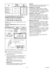
...TV unit.) L = 3 cm INPUT: WHITE 80%, 20% Color Analyzer Note: Use the service remote control unit 1. When "x" value and "y" value are not within specification, adjust "CCOB(C/D2)" or "C-COR(C/D2)". Press [4] button to the center on the remote control unit and select "C/D1" mode. 5-2 A7144EA Only when replacing the LCD... Press [6] button to select "DR(C/D1)" for Blue adjustment. Refer to "1. Initial Setting." [RF/INPUT1]----(APL 20%) Press [3] button to the LCD Panel surface. 4. [RF/INPUT1] Enter the Service mode. Operate the unit for Blue adjustment. Input the White...
...TV unit.) L = 3 cm INPUT: WHITE 80%, 20% Color Analyzer Note: Use the service remote control unit 1. When "x" value and "y" value are not within specification, adjust "CCOB(C/D2)" or "C-COR(C/D2)". Press [4] button to the center on the remote control unit and select "C/D1" mode. 5-2 A7144EA Only when replacing the LCD... Press [6] button to select "DR(C/D1)" for Blue adjustment. Refer to "1. Initial Setting." [RF/INPUT1]----(APL 20%) Press [3] button to the LCD Panel surface. 4. [RF/INPUT1] Enter the Service mode. Operate the unit for Blue adjustment. Input the White...
Service Manual
Page 28
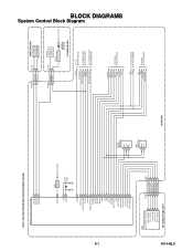
...: CBA AND PWB MEANS PRINTED WIRING BOARD. IC1202 (TV MICRO CONTROLLER) KEY-IN-2 4 KEY-IN-1 3 REMOTE 27 RESET 94 XIN 37 XOUT 38 Q917 RESET AL+3.3V(D) X1301 27MHz VCOM 19 DTV-ON-H 152 BACKLIGHT-SW 157 P-ON-H 28 VGH-H 26 BACKLIGHT-ADJ 20 IF-MUTE 18 INPUT-2 51 INPUT-0 49 INPUT... SENSOR Q1142 LED DRIVE D1142 POWER AL+3.3V(D) IR SENSOR CBA VCOM DTV-ON-H BACKLIGHT-SW P-ON-H VGH-H BACKLIGHT-ADJ TO LCD BLOCK DIAGRAM TO POWER SUPPLY BLOCK DIAGRAM TO LCD BACKLIGHT BLOCK DIAGRAM IF-MUTE INPUT-2 INPUT-0 INPUT-1 S-SW AFT-IN FSC TO IF/VIDEO BLOCK DIAGRAM SCL SDA SCL SDA...
...: CBA AND PWB MEANS PRINTED WIRING BOARD. IC1202 (TV MICRO CONTROLLER) KEY-IN-2 4 KEY-IN-1 3 REMOTE 27 RESET 94 XIN 37 XOUT 38 Q917 RESET AL+3.3V(D) X1301 27MHz VCOM 19 DTV-ON-H 152 BACKLIGHT-SW 157 P-ON-H 28 VGH-H 26 BACKLIGHT-ADJ 20 IF-MUTE 18 INPUT-2 51 INPUT-0 49 INPUT... SENSOR Q1142 LED DRIVE D1142 POWER AL+3.3V(D) IR SENSOR CBA VCOM DTV-ON-H BACKLIGHT-SW P-ON-H VGH-H BACKLIGHT-ADJ TO LCD BLOCK DIAGRAM TO POWER SUPPLY BLOCK DIAGRAM TO LCD BACKLIGHT BLOCK DIAGRAM IF-MUTE INPUT-2 INPUT-0 INPUT-1 S-SW AFT-IN FSC TO IF/VIDEO BLOCK DIAGRAM SCL SDA SCL SDA...
Service Manual
Page 51
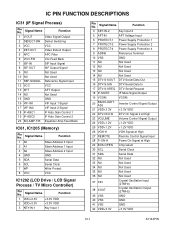
...A1 Slave Address 1 Input 3 A2 Slave Address 2 Input 4 GND GND 5 SDA Serial Data 6 SCL Serial Clock 7 WP Write Protect 8 VCC VCC IC1202 (LCD Drive / LCD Signal Process / TV Micro Controller) Pin No. IC PIN FUNCTION DESCRIPTIONS IC31 (IF Signal Process) Pin No. Signal Name Function 4 KEY-IN-2 Key Input 2 5 AFT-IN AFT...Out 16 DTV-S-SIN DTV Serial Data In 17 DTV-S-SREQ DTV Serial Request 18 IF-MUTE IF Mute Signal Output 19 VCOM VCOM 20 BACKLIGHTADJ Inverter Control Signal Output 21 VDD+3.3V +3.3V VDD 22 DTV-ON-H2 DTV On Signal 2 at High 23 VOLUME Volume Control...
...A1 Slave Address 1 Input 3 A2 Slave Address 2 Input 4 GND GND 5 SDA Serial Data 6 SCL Serial Clock 7 WP Write Protect 8 VCC VCC IC1202 (LCD Drive / LCD Signal Process / TV Micro Controller) Pin No. IC PIN FUNCTION DESCRIPTIONS IC31 (IF Signal Process) Pin No. Signal Name Function 4 KEY-IN-2 Key Input 2 5 AFT-IN AFT...Out 16 DTV-S-SIN DTV Serial Data In 17 DTV-S-SREQ DTV Serial Request 18 IF-MUTE IF Mute Signal Output 19 VCOM VCOM 20 BACKLIGHTADJ Inverter Control Signal Output 21 VDD+3.3V +3.3V VDD 22 DTV-ON-H2 DTV On Signal 2 at High 23 VOLUME Volume Control...


