Installation Manual
Page 49
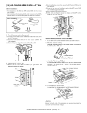
... DATA indicator below it on the MFP control PWB unit and secure it with two screws J. Mount an extended memory to step 4). 3) Mount an extended memory. [10] AR-FX8/AR-MM9 INSTALLATION • For installation of AR-FX8, the MFP control PWB unit must have been installed. •...at an angle. Remove the two screws that secure the MFP control PWB unit to the "OFF" position. Raise the two grips and hold them to the MFP control PWB unit. AR-M550/M620/M700 INSTALLATION MANUAL (AR-FX8) 10 - 1 Parts included FAX interface PWB unit (1 pc.) FAX interface cable (1 pc.) Line ...
... DATA indicator below it on the MFP control PWB unit and secure it with two screws J. Mount an extended memory to step 4). 3) Mount an extended memory. [10] AR-FX8/AR-MM9 INSTALLATION • For installation of AR-FX8, the MFP control PWB unit must have been installed. •...at an angle. Remove the two screws that secure the MFP control PWB unit to the "OFF" position. Raise the two grips and hold them to the MFP control PWB unit. AR-M550/M620/M700 INSTALLATION MANUAL (AR-FX8) 10 - 1 Parts included FAX interface PWB unit (1 pc.) FAX interface cable (1 pc.) Line ...
Installation Manual
Page 50
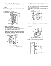
... 10) Connect the FAX interface cable to secure the FAX box unit. Grip Upper right cabinet Cut-out portion FAX interface cable AR-M550/M620/M700 INSTALLATION MANUAL (AR-FX8) 10 - 2 Screws 9) Connect the FAX power connector. Then, connect the FAX power connector to the connector on the...7) Reattach the upper right cabinet. Pass the FAX interface cable behind the FAX box unit and connect it with the FAX power connector. Reattach the MFP control PWB to their original positions. 8) Attach the FAX box unit. Return the grips to the main unit. Remove the screw that has been removed in ...
... 10) Connect the FAX interface cable to secure the FAX box unit. Grip Upper right cabinet Cut-out portion FAX interface cable AR-M550/M620/M700 INSTALLATION MANUAL (AR-FX8) 10 - 2 Screws 9) Connect the FAX power connector. Then, connect the FAX power connector to the connector on the...7) Reattach the upper right cabinet. Pass the FAX interface cable behind the FAX box unit and connect it with the FAX power connector. Reattach the MFP control PWB to their original positions. 8) Attach the FAX box unit. Return the grips to the main unit. Remove the screw that has been removed in ...


