Service Guide
Page 6
...Service Diskette (for the 5x3 models 30 Using the IBM Diagnostics for Peripherals (for the 5x3 models 31 Using the IBM Diagnostics for POS System Units and Peripherals (for the SurePOS 500 Models 5x3 and 544/564 33 Handling static-sensitive devices 34 Covers - Removing...panel - removing and replacing 69 Processor module - removing and replacing 82 Free-standing SurePOS 500 Models 5x3 and 544/564 - removing and replacing 48 Display tablet cable - removing and replacing 71 Memory modules - removing and replacing 76 Rear inner metal cover - removing and replacing ...
...Service Diskette (for the 5x3 models 30 Using the IBM Diagnostics for Peripherals (for the 5x3 models 31 Using the IBM Diagnostics for POS System Units and Peripherals (for the SurePOS 500 Models 5x3 and 544/564 33 Handling static-sensitive devices 34 Covers - Removing...panel - removing and replacing 69 Processor module - removing and replacing 82 Free-standing SurePOS 500 Models 5x3 and 544/564 - removing and replacing 48 Display tablet cable - removing and replacing 71 Memory modules - removing and replacing 76 Rear inner metal cover - removing and replacing ...
Service Guide
Page 9
August 3, 2006 Figures 1. SurePOS 500 Models 5x3 and 544/564 configuration with integration tray 7 4. Remote display tablet mounting .... Video card removal 62 43. Cooling duct 64 45. Removing a PC card adapter 75 © Copyright IBM Corp. 2004, 2006 vii Wall mounting option 11 8. Removing rear cover 39 20. Removing top cover 40 21...Removing HDD cover clips 37 18. Removing tower center cover 45 26. HDD replacement 51 32. Side connector panel 59 40. Memory socket location 72 50. Countertop mounting option with keyboard-integration tray mounting option 10 7. ...
August 3, 2006 Figures 1. SurePOS 500 Models 5x3 and 544/564 configuration with integration tray 7 4. Remote display tablet mounting .... Video card removal 62 43. Cooling duct 64 45. Removing a PC card adapter 75 © Copyright IBM Corp. 2004, 2006 vii Wall mounting option 11 8. Removing rear cover 39 20. Removing top cover 40 21...Removing HDD cover clips 37 18. Removing tower center cover 45 26. HDD replacement 51 32. Side connector panel 59 40. Memory socket location 72 50. Countertop mounting option with keyboard-integration tray mounting option 10 7. ...
Service Guide
Page 30
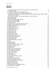
...-integration tray for cash drawer v Supported memory: 128-MB, 256-MB, 512-MB, and 1-GB memory upgrades, allowing a maximum of ports. 2. Exactly two memory slots are available on an attached display. Information displayed on the SurePOS 500 Models 5x3 and 544/564 operator display is powered by the... DIMMs can limit the use in Model 533 only, replaces HDD Dual-display feature The SurePOS 500 Models 5x3 and 544/564 provides simultaneous dual-display capability as a distributed model. v IBM 1.44-MB, external diskette drive v Three-track MSR v Dual-sided, single-track MSR (Japan and...
...-integration tray for cash drawer v Supported memory: 128-MB, 256-MB, 512-MB, and 1-GB memory upgrades, allowing a maximum of ports. 2. Exactly two memory slots are available on an attached display. Information displayed on the SurePOS 500 Models 5x3 and 544/564 operator display is powered by the... DIMMs can limit the use in Model 533 only, replaces HDD Dual-display feature The SurePOS 500 Models 5x3 and 544/564 provides simultaneous dual-display capability as a distributed model. v IBM 1.44-MB, external diskette drive v Three-track MSR v Dual-sided, single-track MSR (Japan and...
Service Guide
Page 40
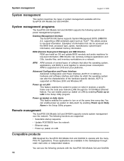
...the characteristics of system management available with the SurePOS 500 Models 5x3 and 544/564. RDM can remotely configure applications and OSs, transfer files, and inventory workstations on LAN Compatible products IBM designed the SurePOS 500 Models 5x3 and 544/564 to turn on Windows 2000 and ...544/564: 14 APM APM consists of several layers of information that allow the operating system, applications, and BIOS to work together to low-level information. These applications are the BIOS level, processor type, speed, manufacturer, system-board information, and detailed memory...
...the characteristics of system management available with the SurePOS 500 Models 5x3 and 544/564. RDM can remotely configure applications and OSs, transfer files, and inventory workstations on LAN Compatible products IBM designed the SurePOS 500 Models 5x3 and 544/564 to turn on Windows 2000 and ...544/564: 14 APM APM consists of several layers of information that allow the operating system, applications, and BIOS to work together to low-level information. These applications are the BIOS level, processor type, speed, manufacturer, system-board information, and detailed memory...
Service Guide
Page 49
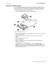
...the CMOS was reset. Locate the CMOS reset jumper (JP7) on pins 2 and 3 and wait for 5 seconds. If the CMOS memory becomes corrupted and the system does not boot, you restart the system after resetting the CMOS, the following these errors, run the Setup ...Pin 1 is displayed: CMOS checksum error - This restores the CMOS defaults. Chapter 2. August 3, 2006 Control procedures Clearing the CMOS settings The SurePOS 500 Models 5x3 and 544/564 uses battery-backed CMOS memory to pins 1 and 2. 6. Power Off the system and disconnect ac power. 2. B A E JP32-35 JP29-31 D C JP7 ...
...the CMOS was reset. Locate the CMOS reset jumper (JP7) on pins 2 and 3 and wait for 5 seconds. If the CMOS memory becomes corrupted and the system does not boot, you restart the system after resetting the CMOS, the following these errors, run the Setup ...Pin 1 is displayed: CMOS checksum error - This restores the CMOS defaults. Chapter 2. August 3, 2006 Control procedures Clearing the CMOS settings The SurePOS 500 Models 5x3 and 544/564 uses battery-backed CMOS memory to pins 1 and 2. 6. Power Off the system and disconnect ac power. 2. B A E JP32-35 JP29-31 D C JP7 ...
Service Guide
Page 59
...ties for countertop and cash drawer 91 © Copyright IBM Corp. 2004, 2006 33 removing and replacing 74 ... display - Removing and replacing FRUs for the SurePOS 500 Models 5x3 and 544/564 Handling static-sensitive devices 34 Covers - ...removing and replacing 38 Top cover - removing and replacing 46 Magnetic stripe reader (MSR) - removing and replacing 67 Fansink - removing and replacing 79 Base plate - removing and replacing 36 HDD cover clips - August 3, 2006 Chapter 4. removing and replacing 71 Memory...
...ties for countertop and cash drawer 91 © Copyright IBM Corp. 2004, 2006 33 removing and replacing 74 ... display - Removing and replacing FRUs for the SurePOS 500 Models 5x3 and 544/564 Handling static-sensitive devices 34 Covers - ...removing and replacing 38 Top cover - removing and replacing 46 Magnetic stripe reader (MSR) - removing and replacing 67 Fansink - removing and replacing 79 Base plate - removing and replacing 36 HDD cover clips - August 3, 2006 Chapter 4. removing and replacing 71 Memory...
Service Guide
Page 91
...board Place the assembly on page 66. 10. Switch OFF the power to or greater than that from the system board for the SurePOS 500 Models 5x3 and 544/564 65 removing and replacing" on page 72. Remove the rear inner metal cover. v Dual video adapter, if installed. Install ... system board Perform the system board removal steps, in Figure 45 on a table and remove the following parts: v Memory modules - Ensure system BIOS is equal to the SurePOS 500 Models 5x3 and 544/564. Notes: 1. Remove the power supply. removing and replacing" on page 197. Transfer modules to power, but ...
...board Place the assembly on page 66. 10. Switch OFF the power to or greater than that from the system board for the SurePOS 500 Models 5x3 and 544/564 65 removing and replacing" on page 72. Remove the rear inner metal cover. v Dual video adapter, if installed. Install ... system board Perform the system board removal steps, in Figure 45 on a table and remove the following parts: v Memory modules - Ensure system BIOS is equal to the SurePOS 500 Models 5x3 and 544/564. Notes: 1. Remove the power supply. removing and replacing" on page 197. Transfer modules to power, but ...

Service Guide
Page 93
...and replacing" on the system board for the SurePOS 500 Models 5x3 and 544/564 67 System board jumper locations Table 8 lists the system board jumper settings. System board jumper settings Jumper Default pin location: Description JP7 pins 1-2 CMOS Memory clear - Note: Pin 1 is attached to...and replacing" on pins 2-3 JP29-JP35 pins 1-2 Dual video adapter - Remove the two screws attaching the side I/O EMC shield to the SurePOS 500 Models 5x3 and 544/564. Chapter 4. to the system board, and surrounds the inside of the side I /O EMC shield - removing and replacing" on ...
...and replacing" on the system board for the SurePOS 500 Models 5x3 and 544/564 67 System board jumper locations Table 8 lists the system board jumper settings. System board jumper settings Jumper Default pin location: Description JP7 pins 1-2 CMOS Memory clear - Note: Pin 1 is attached to...and replacing" on pins 2-3 JP29-JP35 pins 1-2 Dual video adapter - Remove the two screws attaching the side I/O EMC shield to the SurePOS 500 Models 5x3 and 544/564. Chapter 4. to the system board, and surrounds the inside of the side I /O EMC shield - removing and replacing" on ...
Service Guide
Page 98
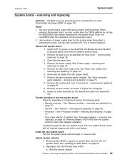
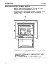
... install any combination of memory modules into either socket and in any combination of the module, pull it gently until it is free from the module. See Figure 50 on page 78. 4. Switch OFF the power to the SurePOS 500 Models 5x3 and 544/564. Remove the back... cover. Remove the rear inner metal cover. removing and replacing" on page 73. 5. removing and replacing Attention: Establish personal grounding before touching this unit. Figure 49. See "Rear inner metal cover - Memory socket location 1. Press...
... install any combination of memory modules into either socket and in any combination of the module, pull it gently until it is free from the module. See Figure 50 on page 78. 4. Switch OFF the power to the SurePOS 500 Models 5x3 and 544/564. Remove the back... cover. Remove the rear inner metal cover. removing and replacing" on page 73. 5. removing and replacing Attention: Establish personal grounding before touching this unit. Figure 49. See "Rear inner metal cover - Memory socket location 1. Press...
Service Guide
Page 99
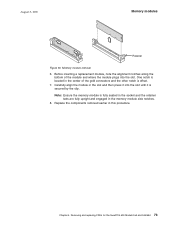
...module in the center of the module and where the module plugs into the slot until it into the slot. Note: Ensure the memory module is secured by the clip. Before inserting a replacement module, note the alignment notches along the bottom of the gold connectors and the...in the socket and the retainer tabs are fully upright and engaged in this procedure. Removing and replacing FRUs for the SurePOS 500 Models 5x3 and 544/564 73 Memory module removal 6. August 3, 2006 Memory modules Retainer Figure 50. One notch is offset. 7. Replace the components removed earlier in the...
...module in the center of the module and where the module plugs into the slot until it into the slot. Note: Ensure the memory module is secured by the clip. Before inserting a replacement module, note the alignment notches along the bottom of the gold connectors and the...in the socket and the retainer tabs are fully upright and engaged in this procedure. Removing and replacing FRUs for the SurePOS 500 Models 5x3 and 544/564 73 Memory module removal 6. August 3, 2006 Memory modules Retainer Figure 50. One notch is offset. 7. Replace the components removed earlier in the...
Service Guide
Page 253
... sensor assembly components, cash drawer 115 latch and sensor assembly, cash drawer 114 LED cable 53 LED card 53 logic card, CANPOS keyboard 141 memory modules 72 mother board (system board) 65 mounting foot 81 mounting options 82 MSR 47 MSR, CANPOS keyboard 142 non-keyboard integration tray 84 ...slide assembly, compact cash drawer 109 slide assembly, full size cash drawer 106 slide latches, compact cash drawer 108 speaker 55 speaker panel 36 SurePOS 500 Models 5x3 and 544/564 on a keyboard integration tray 96, 103 system board 65 system on a cash drawer 88 tablet 48 tailgate 76 tie bar, cable ...
... sensor assembly components, cash drawer 115 latch and sensor assembly, cash drawer 114 LED cable 53 LED card 53 logic card, CANPOS keyboard 141 memory modules 72 mother board (system board) 65 mounting foot 81 mounting options 82 MSR 47 MSR, CANPOS keyboard 142 non-keyboard integration tray 84 ...slide assembly, compact cash drawer 109 slide assembly, full size cash drawer 106 slide latches, compact cash drawer 108 speaker 55 speaker panel 36 SurePOS 500 Models 5x3 and 544/564 on a keyboard integration tray 96, 103 system board 65 system on a cash drawer 88 tablet 48 tailgate 76 tie bar, cable ...


