Service Guide
Page 6
...Magnetic stripe reader (MSR) - removing and replacing 49 Hinge assembly - removing and replacing 50 HDD CompactFlash assembly and HDD bracket - removing and replacing 52 LED card and cable - removing and replacing 58 Connecting the cables and using cable-ties for the SurePOS 500 Models 5x3 and...Troubleshooting 27 CMOS recovery 30 Running Diagnostics 30 Using the Service Diskette (for the 5x3 models 30 Using the IBM Diagnostics for Peripherals (for the 5x3 models 31 Using the IBM Diagnostics for POS System Units and Peripherals (for countertop and cash drawer . . . . 91 removing ...
...Magnetic stripe reader (MSR) - removing and replacing 49 Hinge assembly - removing and replacing 50 HDD CompactFlash assembly and HDD bracket - removing and replacing 52 LED card and cable - removing and replacing 58 Connecting the cables and using cable-ties for the SurePOS 500 Models 5x3 and...Troubleshooting 27 CMOS recovery 30 Running Diagnostics 30 Using the Service Diskette (for the 5x3 models 30 Using the IBM Diagnostics for Peripherals (for the 5x3 models 31 Using the IBM Diagnostics for POS System Units and Peripherals (for countertop and cash drawer . . . . 91 removing ...

Service Guide
Page 7
...of unit with 17-inch display 174 Wall mount dimensions 175 Dimensions of unit with MSR 142 Appendix A. August 3, 2006 Compact-size keyboard integration tray mounting for the cash ... integration tray 130 Mounting the display tablet on a remote display stand 132 Chapter 5. SurePOS 500 Models 5x3 and 544/564 tips 189 Contents v removing and replacing 113 Distributed customer ... External connectors 179 Temperature, humidity, and altitude limits 187 Appendix D. disassembling 118 IBM 4610 SureMark printers - Assembly 6: Cash drawer non-keyboard integration tray and filler ...
...of unit with 17-inch display 174 Wall mount dimensions 175 Dimensions of unit with MSR 142 Appendix A. August 3, 2006 Compact-size keyboard integration tray mounting for the cash ... integration tray 130 Mounting the display tablet on a remote display stand 132 Chapter 5. SurePOS 500 Models 5x3 and 544/564 tips 189 Contents v removing and replacing 113 Distributed customer ... External connectors 179 Temperature, humidity, and altitude limits 187 Appendix D. disassembling 118 IBM 4610 SureMark printers - Assembly 6: Cash drawer non-keyboard integration tray and filler ...
Service Guide
Page 9
...32. Speaker removal 55 35. Mounting foot option 12 9. Removing top cover 40 21. Removing side panel door only 44 25. Display tablet, remove and replace 48 29. LED card and cable, presence sensor 53 33. Removing the PC card adapter slot blank 74 52. SurePOS 500... Models 5x3 and 544/564 configuration with keyboard integration tray, integrated character display and 4820 SurePoint Solution options 9 6. Removing the system board 66 46. Removing rear cover 39 20. Removing the MSR...75 © Copyright IBM Corp. 2004, 2006 vii
...32. Speaker removal 55 35. Mounting foot option 12 9. Removing top cover 40 21. Removing side panel door only 44 25. Display tablet, remove and replace 48 29. LED card and cable, presence sensor 53 33. Removing the PC card adapter slot blank 74 52. SurePOS 500... Models 5x3 and 544/564 configuration with keyboard integration tray, integrated character display and 4820 SurePoint Solution options 9 6. Removing the system board 66 46. Removing rear cover 39 20. Removing the MSR...75 © Copyright IBM Corp. 2004, 2006 vii
Service Guide
Page 11
Removing the keyboard from the integration tray 138 111. Removing the MSR control card 143 Figures ix Tower end of remote display cable 133 109. CANPOS keypad assembly with MSR 142 113. CANPOS Keyboard 137 110. Remote display mounting 132 108. CANPOS keypad assembly without MSR 140 112. August 3, 2006 107.
Removing the keyboard from the integration tray 138 111. Removing the MSR control card 143 Figures ix Tower end of remote display cable 133 109. CANPOS keypad assembly with MSR 142 113. CANPOS Keyboard 137 110. Remote display mounting 132 108. CANPOS keypad assembly without MSR 140 112. August 3, 2006 107.
Service Guide
Page 13
... for CANPOS keyboard problems 135 12. Assignment of parallel-connector pins 183 32. SurePOS 500 Models 5x3 and 544/564 task information 25 7. Unit dimensions 175 17... port assignment 15 5. Keyboard part numbers 137 13. SurePOS 500 Series dimensions 170 15. Power consumption 178 21. MSR connector-pin assignments 179 23. USB port connector-pin assignments...186 36. Assignment of diskette-drive connector pins 184 33. Trademarks 197 © Copyright IBM Corp. 2004, 2006 xi Symptoms and actions 27 8. Assignment of external-video connector ...
... for CANPOS keyboard problems 135 12. Assignment of parallel-connector pins 183 32. SurePOS 500 Models 5x3 and 544/564 task information 25 7. Unit dimensions 175 17... port assignment 15 5. Keyboard part numbers 137 13. SurePOS 500 Series dimensions 170 15. Power consumption 178 21. MSR connector-pin assignments 179 23. USB port connector-pin assignments...186 36. Assignment of diskette-drive connector pins 184 33. Trademarks 197 © Copyright IBM Corp. 2004, 2006 xi Symptoms and actions 27 8. Assignment of external-video connector ...
Service Guide
Page 22
... is necessary to the nearest edge of electrostatic discharge, observe the following precautions: v Limit your system. To reduce the possibility of the magnetic stripe reader (MSR). To avoid damage, keep static-sensitive devices in the liquid crystal display contains mercury. v Do not leave the device where others can cause static electricity...
... is necessary to the nearest edge of electrostatic discharge, observe the following precautions: v Limit your system. To reduce the possibility of the magnetic stripe reader (MSR). To avoid damage, keep static-sensitive devices in the liquid crystal display contains mercury. v Do not leave the device where others can cause static electricity...
Service Guide
Page 30
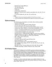
... available on an attached display. v IBM 1.44-MB, external diskette drive v Three-track MSR v Dual-sided, single-track MSR (Japan and Korea only) v Mouse and keyboard "Y" cable v IBM SurePOS 500/600 Series Compact ANPOS Keyboard v 4610 SureMark Printer (Models TF6, TF7, IF6, TG3, TG4, TG5, TI3, TI4, TI5, DG3, and DG4) v IBM 4820 SurePoint® Solutions (Models 4FT...
... available on an attached display. v IBM 1.44-MB, external diskette drive v Three-track MSR v Dual-sided, single-track MSR (Japan and Korea only) v Mouse and keyboard "Y" cable v IBM SurePOS 500/600 Series Compact ANPOS Keyboard v 4610 SureMark Printer (Models TF6, TF7, IF6, TG3, TG4, TG5, TI3, TI4, TI5, DG3, and DG4) v IBM 4820 SurePoint® Solutions (Models 4FT...
Service Guide
Page 55
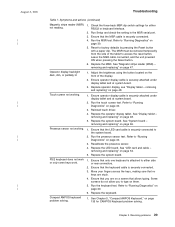
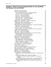
... - Run the touch screen test. Ensure that the LED card cable is attached to "Running Diagnostics" on them. 5. Ensure that the MSR cable is securely connected. 3. Compact ANPOS keyboard problem solving. 1. Ensure that you to "Running Diagnostics" on page 135 for either side or...Setup and check the setting in the MSR serial port. 3. Run the MSR test. Refer to "Running Diagnostics" on page 30. 5. The MSR must be removed temporarily from the side of the display. 2. Replace the MSR. See "Magnetic stripe reader (MSR) - Ensure operator display cable is ...
... - Run the touch screen test. Ensure that the LED card cable is attached to "Running Diagnostics" on them. 5. Ensure that the MSR cable is securely connected. 3. Compact ANPOS keyboard problem solving. 1. Ensure that you to "Running Diagnostics" on page 135 for either side or...Setup and check the setting in the MSR serial port. 3. Run the MSR test. Refer to "Running Diagnostics" on page 30. 5. The MSR must be removed temporarily from the side of the display. 2. Replace the MSR. See "Magnetic stripe reader (MSR) - Ensure operator display cable is ...
Service Guide
Page 59
...MSR) - removing and replacing 53 Calibrating the presence sensor (Models 563, 564, 573, and 5A3 only) . . . 54 Speaker - removing and replacing 57 Cable tie bar - removing and replacing 71 Memory modules - removing and replacing 80 Mounting foot - removing and replacing 81 Mounting options - removing and replacing 82 Free-standing SurePOS 500...removing and replacing 58 Connecting the cables and using cable-ties for countertop and cash drawer 91 © Copyright IBM Corp. 2004, 2006 33 removing and replacing 76 Rear inner metal cover - removing and replacing 50 HDD ...
...MSR) - removing and replacing 53 Calibrating the presence sensor (Models 563, 564, 573, and 5A3 only) . . . 54 Speaker - removing and replacing 57 Cable tie bar - removing and replacing 71 Memory modules - removing and replacing 80 Mounting foot - removing and replacing 81 Mounting options - removing and replacing 82 Free-standing SurePOS 500...removing and replacing 58 Connecting the cables and using cable-ties for countertop and cash drawer 91 © Copyright IBM Corp. 2004, 2006 33 removing and replacing 76 Rear inner metal cover - removing and replacing 50 HDD ...

Service Guide
Page 73
... and off. Note: If you are replacing a dual-sided, single-track MSR, you must set the switch under the MSR cover next to the slot to the SurePOS 500 Models 5x3 and 544/564. Removing and replacing FRUs for the SurePOS 500 Models 5x3 and 544/564 47 Switch OFF the power to either the RS...
... and off. Note: If you are replacing a dual-sided, single-track MSR, you must set the switch under the MSR cover next to the slot to the SurePOS 500 Models 5x3 and 544/564. Removing and replacing FRUs for the SurePOS 500 Models 5x3 and 544/564 47 Switch OFF the power to either the RS...

Service Guide
Page 161
... CANPOS Keyboard components - Two PS/2-style keyboard ports are programmed by calling 1-800-IBM-CALL (1-800-426-2255) in the port where the keyboard is not operational). ...keyboard cable. 4. The 32 programmable keys are provided, but only one may be inserted onto the programmable keys to determine the failing CANPOS keyboard FRU. See the SurePOS 500/600 Installation and Operations... a QWERTY layout, an integrated pointing device, a numeric keypad, and 32 programmable keys. The redesigned cap (with MSR 142 This chapter contains repair and usage information for more information on the...
... CANPOS Keyboard components - Two PS/2-style keyboard ports are programmed by calling 1-800-IBM-CALL (1-800-426-2255) in the port where the keyboard is not operational). ...keyboard cable. 4. The 32 programmable keys are provided, but only one may be inserted onto the programmable keys to determine the failing CANPOS keyboard FRU. See the SurePOS 500/600 Installation and Operations... a QWERTY layout, an integrated pointing device, a numeric keypad, and 32 programmable keys. The redesigned cap (with MSR 142 This chapter contains repair and usage information for more information on the...
Service Guide
Page 162
...not resolved, then replace the keypad assembly. Push the joystick to its maximum deflection in each direction. 2. Repair actions for 2-3 seconds in the MSR serial port. 2. Run the Setup Utility and check the setting in each direction - When the computer initially boots up , down, left, ...Repair actions The cursor responds sluggishly or does not move when using the CANPOS keyboard with MSR" on page 142. 136 Ensure that the MSR cable are securely connected inside the keyboard. 5. Replace the MSR. See "CANPOS keyboard with integrated pointing device. Make sure data appears. 4. up ,...
...not resolved, then replace the keypad assembly. Push the joystick to its maximum deflection in each direction. 2. Repair actions for 2-3 seconds in the MSR serial port. 2. Run the Setup Utility and check the setting in each direction - When the computer initially boots up , down, left, ...Repair actions The cursor responds sluggishly or does not move when using the CANPOS keyboard with MSR" on page 142. 136 Ensure that the MSR cable are securely connected inside the keyboard. 5. Replace the MSR. See "CANPOS keyboard with integrated pointing device. Make sure data appears. 4. up ,...

Service Guide
Page 163
...If you do not need to remove any keyboard components. and Canada. and Canada should be purchased by calling 1-800-IBM-CALL (1-800-426-2255) in the following table are no longer available; CANPOS Keyboard Notes: 1. FRUs for new .... See "Assembly 4: Optional features" on page 152 for the keyboards listed in the U.S. removing and replacing Figure 109 shows the CANPOS keyboard and its components: MSR 32 Programmable Keys Esc F1 F2 F3 F4 F5 F6 F7 F8 F9 F10 F11 F12 PrtSc SysRq _! ` 1 @# 2 3 $ %^ 4 5 6 & * ( ) 7 8 9 0 _+ - = Backspace Tab QWE R T Y U...
...If you do not need to remove any keyboard components. and Canada. and Canada should be purchased by calling 1-800-IBM-CALL (1-800-426-2255) in the following table are no longer available; CANPOS Keyboard Notes: 1. FRUs for new .... See "Assembly 4: Optional features" on page 152 for the keyboards listed in the U.S. removing and replacing Figure 109 shows the CANPOS keyboard and its components: MSR 32 Programmable Keys Esc F1 F2 F3 F4 F5 F6 F7 F8 F9 F10 F11 F12 PrtSc SysRq _! ` 1 @# 2 3 $ %^ 4 5 6 & * ( ) 7 8 9 0 _+ - = Backspace Tab QWE R T Y U...
Service Guide
Page 164
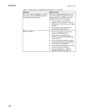
... integration tray to service the keyboard. 1. CANPOS Keyboard Table 12. Keyboard part numbers (continued) Keyboard P/N Description 54P8790 Spanish 54P8791 Brazilian Portuguese 54P8792 German August 3, 2006 MSR Yes Yes Yes CANPOS keypad assembly You must remove the keyboard from the integration tray b.
... integration tray to service the keyboard. 1. CANPOS Keyboard Table 12. Keyboard part numbers (continued) Keyboard P/N Description 54P8790 Spanish 54P8791 Brazilian Portuguese 54P8792 German August 3, 2006 MSR Yes Yes Yes CANPOS keypad assembly You must remove the keyboard from the integration tray b.

Service Guide
Page 166
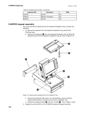
See Figure 111 for cable callouts and locations. Disconnect all cables between the keypad assembly and the keyboard logic card. To reinstall the keypad assembly, reverse these steps. 140 Keypad Assembly Ribbon Cable, to J3 Ribbon Cable, to J4 Keyboard Logic card J4 J3 Latch to J5 Ribbon Cable to MJ1 J5 J1 Ribbon Cable Connectors MJ1 Integrated Pointing Device Connector Figure 111. CANPOS keypad assembly without MSR 3. CANPOS Keyboard August 3, 2006 d. Lift and remove the keypad assembly.
See Figure 111 for cable callouts and locations. Disconnect all cables between the keypad assembly and the keyboard logic card. To reinstall the keypad assembly, reverse these steps. 140 Keypad Assembly Ribbon Cable, to J3 Ribbon Cable, to J4 Keyboard Logic card J4 J3 Latch to J5 Ribbon Cable to MJ1 J5 J1 Ribbon Cable Connectors MJ1 Integrated Pointing Device Connector Figure 111. CANPOS keypad assembly without MSR 3. CANPOS Keyboard August 3, 2006 d. Lift and remove the keypad assembly.
Service Guide
Page 168
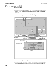
See "CANPOS keypad assembly" on the keypad assembly. CANPOS keypad assembly with MSR To remove the MSR: 1. Keypad Assembly MSR MSR control card to J2 MSR screws Ribbon Cable, to J3 Ribbon Cable, to J4 MSR connector Keyboard Logic card J2 J4 J3 Latch to J5 Ribbon Cable to the keypad assembly as shown in ...Figure 112. Lift the MSR up and off the the two plastic guides on page 138. 2. Remove the MSR control card by placing a small slotted screwdriver between the metal keypad assembly and the bottom of the...
See "CANPOS keypad assembly" on the keypad assembly. CANPOS keypad assembly with MSR To remove the MSR: 1. Keypad Assembly MSR MSR control card to J2 MSR screws Ribbon Cable, to J3 Ribbon Cable, to J4 MSR connector Keyboard Logic card J2 J4 J3 Latch to J5 Ribbon Cable to the keypad assembly as shown in ...Figure 112. Lift the MSR up and off the the two plastic guides on page 138. 2. Remove the MSR control card by placing a small slotted screwdriver between the metal keypad assembly and the bottom of the...

Service Guide
Page 169
... plastic guide, as shown in Figure 112 on the keypad assembly and slide the MSR into the two plastic guides. Before installing the MSR onto the keypad assembly, route the thin ribbon cable from the MSR control card to the CANPOS keyboard. Chapter 5. Compact ANPOS Keyboard 143 Align the...screws, as shown in Figure 113. The CANPOS Keyboard Utility program can be used to download the programmable MSR information to the MSR under the plastic clip on page 138. MSR Control Card MSR Reader A Figure 113. August 3, 2006 CANPOS Keyboard pry the control card up and off the two plastic...
... plastic guide, as shown in Figure 112 on the keypad assembly and slide the MSR into the two plastic guides. Before installing the MSR onto the keypad assembly, route the thin ribbon cable from the MSR control card to the CANPOS keyboard. Chapter 5. Compact ANPOS Keyboard 143 Align the...screws, as shown in Figure 113. The CANPOS Keyboard Utility program can be used to download the programmable MSR information to the MSR under the plastic clip on page 138. MSR Control Card MSR Reader A Figure 113. August 3, 2006 CANPOS Keyboard pry the control card up and off the two plastic...
Service Guide
Page 179
... 41D0152 39V5069 40N5755 06P5223 42M5864 14R0029 41D0149 Assembly 4: (continued) Units Description Optional features 1 MSR, three-track, (Models 5x3 and 544/564 except 573) 1 MSR, three-track, (Model 573 only) 1 MSR, dual sided single track, (Models 5x3 and 544/564 except 573) 1 MSR, dual sided single track, (Model 573 only) 1 Speaker kit (Models 553, 563...
... 41D0152 39V5069 40N5755 06P5223 42M5864 14R0029 41D0149 Assembly 4: (continued) Units Description Optional features 1 MSR, three-track, (Models 5x3 and 544/564 except 573) 1 MSR, three-track, (Model 573 only) 1 MSR, dual sided single track, (Models 5x3 and 544/564 except 573) 1 MSR, dual sided single track, (Model 573 only) 1 Speaker kit (Models 553, 563...
Service Guide
Page 195
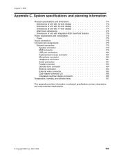
... 4820 SurePoint Solution 176 Power requirements and consumption 178 Power 178 Output connectors 178 Connector-pin assignments 179 External connectors 179 Speaker connector 179 MSR connector 179 USB port connectors 180 Keyboard and mouse connector 180 Microphone connector 180 Headphone connector 181 Serial connectors 181 Parallel connector 183 Diskette-... display connector 186 Temperature, humidity, and altitude limits 187 This appendix provides information on physical specifications, power subsystems, and environmental requirements. © Copyright IBM Corp. 2004, 2006 169
... 4820 SurePoint Solution 176 Power requirements and consumption 178 Power 178 Output connectors 178 Connector-pin assignments 179 External connectors 179 Speaker connector 179 MSR connector 179 USB port connectors 180 Keyboard and mouse connector 180 Microphone connector 180 Headphone connector 181 Serial connectors 181 Parallel connector 183 Diskette-... display connector 186 Temperature, humidity, and altitude limits 187 This appendix provides information on physical specifications, power subsystems, and environmental requirements. © Copyright IBM Corp. 2004, 2006 169

Service Guide
Page 196
... (418 mm) Tablet with 12 in . tablet Tower and 15-in . (375 mm) Table 15. with 15 in . with 17 in . with 17 in . SurePOS 500 Series weights Component Tower and 12-in . tablet Tower and 17-in . Tablet Tablet Tablet Tablet Tablet Tablet Tablet at 15° 10.39 in... kg (29.7 lbs) 5.67 kg (12.5 lbs) 0.21 kg (0.38 lbs) 0.55 kg (1.2 lbs) 170 August 3, 2006 Physical specifications and dimensions The SurePOS 500 Series physical specifications are described in . MSR (364 mm) (426 mm) (461 mm) (364 mm) (426 mm) (461 mm) Base 8.35 in. 8.35 in. 8.35 in. 8.54 in....
... (418 mm) Tablet with 12 in . tablet Tower and 15-in . (375 mm) Table 15. with 15 in . with 17 in . with 17 in . SurePOS 500 Series weights Component Tower and 12-in . tablet Tower and 17-in . Tablet Tablet Tablet Tablet Tablet Tablet Tablet at 15° 10.39 in... kg (29.7 lbs) 5.67 kg (12.5 lbs) 0.21 kg (0.38 lbs) 0.55 kg (1.2 lbs) 170 August 3, 2006 Physical specifications and dimensions The SurePOS 500 Series physical specifications are described in . MSR (364 mm) (426 mm) (461 mm) (364 mm) (426 mm) (461 mm) Base 8.35 in. 8.35 in. 8.35 in. 8.54 in....