Service Guide
Page 5
... 18 Starting the Setup Utility 19 Updating the flash BIOS 22 Power interruption during flash BIOS update procedure 22 Repairing the flash BIOS 22 Real-time clock and CMOS 22 Restoring the default CMOS settings 22 Clearing the CMOS settings 23 Chapter 3. Resolving problems 25 Start problem diagnosis here 25 Preliminary checklist 26 © Copyright IBM Corp. 2004, 2006 iii Introducing the IBM SurePOS 500 Series Models 533, 543, 544, 553, 563, 564, 573, and 5A3 1 SurePOS 500 Models 5x3 and 544/564 2 SurePOS 500 Models...
... 18 Starting the Setup Utility 19 Updating the flash BIOS 22 Power interruption during flash BIOS update procedure 22 Repairing the flash BIOS 22 Real-time clock and CMOS 22 Restoring the default CMOS settings 22 Clearing the CMOS settings 23 Chapter 3. Resolving problems 25 Start problem diagnosis here 25 Preliminary checklist 26 © Copyright IBM Corp. 2004, 2006 iii Introducing the IBM SurePOS 500 Series Models 533, 543, 544, 553, 563, 564, 573, and 5A3 1 SurePOS 500 Models 5x3 and 544/564 2 SurePOS 500 Models...
Service Guide
Page 6
... . . 59 Connecting cables to the side access panel 59 Connecting cables to the rear connector panel 59 Dual-video adapter - removing and replacing 43 Tower center cover - removing and replacing 46 Magnetic stripe reader (MSR) - removing and replacing 55 Power supply - removing and replacing 67 System-board battery - removing and replacing 69 Processor module - removing and replacing 74 Rear connector panel (tailgate) - | | | | | | iv August 3, 2006 Troubleshooting 27 CMOS recovery 30 Running Diagnostics 30 Using the Service Diskette (for the 5x3 models 30 Using the IBM...
... . . 59 Connecting cables to the side access panel 59 Connecting cables to the rear connector panel 59 Dual-video adapter - removing and replacing 43 Tower center cover - removing and replacing 46 Magnetic stripe reader (MSR) - removing and replacing 55 Power supply - removing and replacing 67 System-board battery - removing and replacing 69 Processor module - removing and replacing 74 Rear connector panel (tailgate) - | | | | | | iv August 3, 2006 Troubleshooting 27 CMOS recovery 30 Running Diagnostics 30 Using the Service Diskette (for the 5x3 models 30 Using the IBM...
Service Guide
Page 9
... Power Management window 21 15. Removing HDD cover clips 37 18. Unlatching rear cover 38 19. Removing rear cover 39 20. Side panel door location 43 24. Latch 49 30. Cable routing 61 42. Dual video adapter jumper location 63 44. Memory module removal 73 51. SurePOS 500 Models 5x3 and 544/564 configuration with keyboard integration tray, integrated character display and 4820 SurePoint Solution options 9 6. Cash-drawer mounting option with optional features 2 2. Example of the Advanced BIOS Features window 20 14. CMOS reset jumper...
... Power Management window 21 15. Removing HDD cover clips 37 18. Unlatching rear cover 38 19. Removing rear cover 39 20. Side panel door location 43 24. Latch 49 30. Cable routing 61 42. Dual video adapter jumper location 63 44. Memory module removal 73 51. SurePOS 500 Models 5x3 and 544/564 configuration with keyboard integration tray, integrated character display and 4820 SurePoint Solution options 9 6. Cash-drawer mounting option with optional features 2 2. Example of the Advanced BIOS Features window 20 14. CMOS reset jumper...
Service Guide
Page 13
...-drive connector pins 184 33. Trademarks 197 © Copyright IBM Corp. 2004, 2006 xi Default serial-port assignments 15 3. PS/2 keyboard/mouse port assignment 15 5. Using the touch screen 17 6. SurePOS 500 Series weights 170 16. SurePOS 500 Series power supply 178 20. RJ-45 connector-pin assignments 181 30. USB port connector-pin assignments 180 25. Microphone connector-pin assignments 181 27. Ethernet connector-pin assignments 184 34. Service personnel tools 189 39. Keyboard and mouse connector-pin assignments 180 26. Repair actions for 9-pin serial...
...-drive connector pins 184 33. Trademarks 197 © Copyright IBM Corp. 2004, 2006 xi Default serial-port assignments 15 3. PS/2 keyboard/mouse port assignment 15 5. Using the touch screen 17 6. SurePOS 500 Series weights 170 16. SurePOS 500 Series power supply 178 20. RJ-45 connector-pin assignments 181 30. USB port connector-pin assignments 180 25. Microphone connector-pin assignments 181 27. Ethernet connector-pin assignments 184 34. Service personnel tools 189 39. Keyboard and mouse connector-pin assignments 180 26. Repair actions for 9-pin serial...
Service Guide
Page 23
..., 573, and 5A3, GA27-4330 This guide provides installation and setup information, including option installation procedures and problem determination information. Note: References in this document) This document provides information on repairing and maintaining the system unit, including parts listings, troubleshooting, and removal and replacement procedures. references to Model 544 also apply to : www.ibm.com/solutions/retail/store/. 2. references to Model 564 also apply to...
..., 573, and 5A3, GA27-4330 This guide provides installation and setup information, including option installation procedures and problem determination information. Note: References in this document) This document provides information on repairing and maintaining the system unit, including parts listings, troubleshooting, and removal and replacement procedures. references to Model 544 also apply to : www.ibm.com/solutions/retail/store/. 2. references to Model 564 also apply to...
Service Guide
Page 30
... cash drawer v Supported memory: 128-MB, 256-MB, 512-MB, and 1-GB memory upgrades, allowing a maximum of the SurePOS 500 Models 5x3 and 544/564 or attached as a standard feature. Two supported DIMMs can be used at a time. Other external VGA devices can be connected to the SurePOS 500 Models 5x3 and 544/564 15-pin video port. | In addition, an optional, independent display can limit the use in Model 533 only, replaces HDD Dual-display feature The SurePOS 500 Models 5x3 and...
... cash drawer v Supported memory: 128-MB, 256-MB, 512-MB, and 1-GB memory upgrades, allowing a maximum of the SurePOS 500 Models 5x3 and 544/564 or attached as a standard feature. Two supported DIMMs can be used at a time. Other external VGA devices can be connected to the SurePOS 500 Models 5x3 and 544/564 15-pin video port. | In addition, an optional, independent display can limit the use in Model 533 only, replaces HDD Dual-display feature The SurePOS 500 Models 5x3 and...
Service Guide
Page 31
... you to use a wireless card on self-test (POST) v Configuration/Setup Utility program v Advanced Power Management (APM) (DOS and Linux only) v Advanced Configuration and Power Interface (ACPI)1 v Flash-update utility program | v SurePOS 500 Models 5x3 and 544/564 Diagnostic programs v Device drivers 1. System software features The SurePOS 500 Models 5x3 and 544/564 supports the following operating systems: v PC DOS 2000 v Microsoft® Windows® 2000 v Windows XP/XPe | v IBM Retail Environment for PC Card cards. ACPI is supported only on LAN or...
... you to use a wireless card on self-test (POST) v Configuration/Setup Utility program v Advanced Power Management (APM) (DOS and Linux only) v Advanced Configuration and Power Interface (ACPI)1 v Flash-update utility program | v SurePOS 500 Models 5x3 and 544/564 Diagnostic programs v Device drivers 1. System software features The SurePOS 500 Models 5x3 and 544/564 supports the following operating systems: v PC DOS 2000 v Microsoft® Windows® 2000 v Windows XP/XPe | v IBM Retail Environment for PC Card cards. ACPI is supported only on LAN or...
Service Guide
Page 40
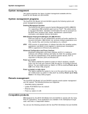
... the operating system, applications, and BIOS to work together to power on Windows 2000 and Windows XP. APM is supported on when it receives a specific frame over the network. You can enable power up on at the same time every day. Examples of the hardware-specific devices. IBM Director can install an OS and update BIOS remotely and probe machines for low-level information. Remote management The SurePOS 500 Models 5x3 and 544/564 supports remote system management...
... the operating system, applications, and BIOS to work together to power on Windows 2000 and Windows XP. APM is supported on when it receives a specific frame over the network. You can enable power up on at the same time every day. Examples of the hardware-specific devices. IBM Director can install an OS and update BIOS remotely and probe machines for low-level information. Remote management The SurePOS 500 Models 5x3 and 544/564 supports remote system management...
Service Guide
Page 48
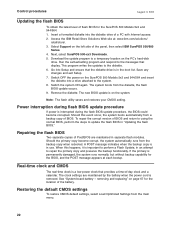
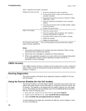
... copy when rebooted. See "System-board battery - Note: The flash utility saves and restores your CMOS setting. Repairing the flash BIOS Two separate copies of BIOS and return to using the normal BIOS, perform the steps to perform a Flash Update, in the boot list. Restoring the default CMOS settings To restore CMOS default settings, select Load Optimized Settings from the diskette, the flash BIOS update occurs. 9. The new BIOS update is interrupted during the flash BIOS update procedure, the BIOS could become corrupt, the system automatically runs from...
... copy when rebooted. See "System-board battery - Note: The flash utility saves and restores your CMOS setting. Repairing the flash BIOS Two separate copies of BIOS and return to using the normal BIOS, perform the steps to perform a Flash Update, in the boot list. Restoring the default CMOS settings To restore CMOS default settings, select Load Optimized Settings from the diskette, the flash BIOS update occurs. 9. The new BIOS update is interrupted during the flash BIOS update procedure, the BIOS could become corrupt, the system automatically runs from...
Service Guide
Page 49
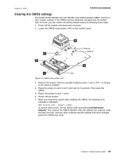
... 3, 2006 Control procedures Clearing the CMOS settings The SurePOS 500 Models 5x3 and 544/564 uses battery-backed CMOS memory to pins 1 and 2. 6. Place the jumper on the system board. Power Off the system and disconnect ac power. 2. Remove the jumper, which is normally located on pins 1 and 2. (Pin 1 is displayed: CMOS checksum error - If the CMOS memory becomes corrupted and the system does not boot, you restart the system after resetting the CMOS, the following these errors, run the Setup Utility and...
... 3, 2006 Control procedures Clearing the CMOS settings The SurePOS 500 Models 5x3 and 544/564 uses battery-backed CMOS memory to pins 1 and 2. 6. Place the jumper on the system board. Power Off the system and disconnect ac power. 2. Remove the jumper, which is normally located on pins 1 and 2. (Pin 1 is displayed: CMOS checksum error - If the CMOS memory becomes corrupted and the system does not boot, you restart the system after resetting the CMOS, the following these errors, run the Setup Utility and...
Service Guide
Page 51
... 6. "The Setup Utility" on page 26. "Running Diagnostics" on page 145. Appendix A, "Parts catalog," on page 30 Look up a part number. Appendix D, "SurePOS 500 Models 5x3 and 544/564 tips," on page 33. Update the flash BIOS. Review service tips. Resolving problems Start problem diagnosis here 25 Preliminary checklist 26 Troubleshooting 27 CMOS recovery 30 | Running Diagnostics 30 | Using the Service Diskette (for the 5x3 models 30 | Using the IBM Diagnostics for Peripherals (for the 5x3 models 31 | Using the IBM Diagnostics for...
... 6. "The Setup Utility" on page 26. "Running Diagnostics" on page 145. Appendix A, "Parts catalog," on page 30 Look up a part number. Appendix D, "SurePOS 500 Models 5x3 and 544/564 tips," on page 33. Update the flash BIOS. Review service tips. Resolving problems Start problem diagnosis here 25 Preliminary checklist 26 Troubleshooting 27 CMOS recovery 30 | Running Diagnostics 30 | Using the Service Diskette (for the 5x3 models 30 | Using the IBM Diagnostics for Peripherals (for the 5x3 models 31 | Using the IBM Diagnostics for...

Service Guide
Page 53
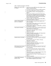
No power light on page 57. 5. removing and replacing" on the tower unit. 1. Run the operator display test. Replace the keylock insert if the lock does not turn with the key. Replace the actuator rod if necessary. Verify the LED card cable is plugged in an attempt to fix a problem, go to "Clearing the CMOS settings" on page 23 and reset CMOS to see Table 7 to the open when cash drawer key is binding. Adjust...
No power light on page 57. 5. removing and replacing" on the tower unit. 1. Run the operator display test. Replace the keylock insert if the lock does not turn with the key. Replace the actuator rod if necessary. Verify the LED card cable is plugged in an attempt to fix a problem, go to "Clearing the CMOS settings" on page 23 and reset CMOS to see Table 7 to the open when cash drawer key is binding. Adjust...
Service Guide
Page 55
... MSR serial port. 3. Run the MSR test. Refer to "Running Diagnostics" on page 135 for either side or rear connectors. 2. removing and replacing" on page 65. Operator display backlight: dark, dim, or partially lit. 1. Adjust the brightness using the button located on page 53. 5. Replace operator display, see "Display tablet - Run the touch screen test. Reinstall touch driver. 4. Replace the operator display tablet. See "Display tablet - Replace the system board. See "System board - Ensure that the keyboard cable is attached to access the reset button...
... MSR serial port. 3. Run the MSR test. Refer to "Running Diagnostics" on page 135 for either side or rear connectors. 2. removing and replacing" on page 65. Operator display backlight: dark, dim, or partially lit. 1. Adjust the brightness using the button located on page 53. 5. Replace operator display, see "Display tablet - Run the touch screen test. Reinstall touch driver. 4. Replace the operator display tablet. See "Display tablet - Replace the system board. See "System board - Ensure that the keyboard cable is attached to access the reset button...
Service Guide
Page 56
... new model power supplies. Ensure that pertain to the system have test instructions. Check the speaker cable connections. Fan continues running after This is enabled. 3. Replace the speaker. 5. Refer to make sure the diskette drive controller is normal operation with the system. Go to configure and test the system and | I/O devices. Replace the system board. See "Speaker - Run Setup Utility to those instructions when testing those messages. Notes: 1. Troubleshooting August 3, 2006 Table 7. However, you may receive error messages that the correct boot device...
... new model power supplies. Ensure that pertain to the system have test instructions. Check the speaker cable connections. Fan continues running after This is enabled. 3. Replace the speaker. 5. Refer to make sure the diskette drive controller is normal operation with the system. Go to configure and test the system and | I/O devices. Replace the system board. See "Speaker - Run Setup Utility to those instructions when testing those messages. Notes: 1. Troubleshooting August 3, 2006 Table 7. However, you may receive error messages that the correct boot device...
Service Guide
Page 57
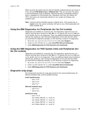
...| Ethernet loopback plug | v pins 3 to 7 | v pins 6 to 8 | parallel port plug | v pins 1 to acquire the diagnostics: | 1. Under SurePOS 500/600 Series select SurePOS 500-xx4 Downloads. | 3. Select IBM Diagnostics for POS Systems and Peripherals | Diagnostic wrap plugs | The following to 13 | v pin 2 diode 1N4149 -| There are shown in | a box. Go to be diagnosed. August 3, 2006 Troubleshooting | When you boot the system with the Service Diskette, detected devices are additional details about selecting a | memory key, setting up , and running...
...| Ethernet loopback plug | v pins 3 to 7 | v pins 6 to 8 | parallel port plug | v pins 1 to acquire the diagnostics: | 1. Under SurePOS 500/600 Series select SurePOS 500-xx4 Downloads. | 3. Select IBM Diagnostics for POS Systems and Peripherals | Diagnostic wrap plugs | The following to 13 | v pin 2 diode 1N4149 -| There are shown in | a box. Go to be diagnosed. August 3, 2006 Troubleshooting | When you boot the system with the Service Diskette, detected devices are additional details about selecting a | memory key, setting up , and running...
Service Guide
Page 59
...removing and replacing 69 Processor module - removing and replacing 74 Rear connector panel (tailgate) - removing and replacing 76 Rear inner metal cover - removing and replacing 80 Mounting foot - removing and replacing 81 Mounting options - removing and replacing 52 LED card and cable - removing from the base 82 Non-keyboard integration tray - removing and replacing 50 HDD CompactFlash assembly and HDD bracket - removing and replacing . . . 51 HDD cables - removing and replacing 57 Cable tie bar - removing and replacing 65 System-board jumper locations and settings...
...removing and replacing 69 Processor module - removing and replacing 74 Rear connector panel (tailgate) - removing and replacing 76 Rear inner metal cover - removing and replacing 80 Mounting foot - removing and replacing 81 Mounting options - removing and replacing 52 LED card and cable - removing from the base 82 Non-keyboard integration tray - removing and replacing 50 HDD CompactFlash assembly and HDD bracket - removing and replacing . . . 51 HDD cables - removing and replacing 57 Cable tie bar - removing and replacing 65 System-board jumper locations and settings...
Service Guide
Page 249
... card 74 board, system 65 C cable tie bar removing and replacing 58 cables and cable-ties installing 59 calibrating presence sensor 54 cap, pointer 135 cash drawer troubleshooting 27 Cash drawer connector pin assignments 186 cash drawer FRUs removing and replacing 105 cash-drawer mounting option 9 © Copyright IBM Corp. 2004, 2006 checklist, problem diagnosis 26 clearing CMOS settings 23 system password 21 clock, real-time 22 CMOS RAM 22 recovery 30 settings clearing 23 restoring defaults...
... card 74 board, system 65 C cable tie bar removing and replacing 58 cables and cable-ties installing 59 calibrating presence sensor 54 cap, pointer 135 cash drawer troubleshooting 27 Cash drawer connector pin assignments 186 cash drawer FRUs removing and replacing 105 cash-drawer mounting option 9 © Copyright IBM Corp. 2004, 2006 checklist, problem diagnosis 26 clearing CMOS settings 23 system password 21 clock, real-time 22 CMOS RAM 22 recovery 30 settings clearing 23 restoring defaults...
Service Guide
Page 250
... connectors 179 External video connector pin assignments 185 F fansink removing and replacing 69 features i, 2 accessibility 198 dual display feature 4 optional 4 standard 3 system management 14 system software 5 flash BIOS update procedure 22 power interruption 22 flash, update 22 foot, mounting removing and replacing 81 free standing mounting option 6 removing and replacing 82 FRUs system board 148 wall mount 150 full size cash drawer removing and replacing 105 August 3, 2006 H handling static-sensitive devices xx, 34 hard disk time-out configuration 21 HDD cables 52 HDD cover 36 HDD fan...
... connectors 179 External video connector pin assignments 185 F fansink removing and replacing 69 features i, 2 accessibility 198 dual display feature 4 optional 4 standard 3 system management 14 system software 5 flash BIOS update procedure 22 power interruption 22 flash, update 22 foot, mounting removing and replacing 81 free standing mounting option 6 removing and replacing 82 FRUs system board 148 wall mount 150 full size cash drawer removing and replacing 105 August 3, 2006 H handling static-sensitive devices xx, 34 hard disk time-out configuration 21 HDD cables 52 HDD cover 36 HDD fan...
Service Guide
Page 253
...100 y-cable, keyboard integration tray 93 replacement parts 145 replacing FRUs 34 requirements power 178 resolving problems 25 restoring default CMOS settings 22 RJ-45 connector pin assignments 181 rollers removing and replacing 110 running diagnostics 30 running setup utility 18 S safety laser xiii notice translations xiii notices xiii safety information xiii, 199 safety notices 201 security clip, removing and replacing 112 serial number location 16 serial number, location 20 serial port 15 Service Diskette 30 service tools 189 setting changing, clearing password 21 clearing CMOS 23 restoring...
...100 y-cable, keyboard integration tray 93 replacement parts 145 replacing FRUs 34 requirements power 178 resolving problems 25 restoring default CMOS settings 22 RJ-45 connector pin assignments 181 rollers removing and replacing 110 running diagnostics 30 running setup utility 18 S safety laser xiii notice translations xiii notices xiii safety information xiii, 199 safety notices 201 security clip, removing and replacing 112 serial number location 16 serial number, location 20 serial port 15 Service Diskette 30 service tools 189 setting changing, clearing password 21 clearing CMOS 23 restoring...
Service Guide
Page 254
... software options 5 speaker 55 speaker panel 36 speaker, connector pin assignments 179 specifications height 170 weight 170 standard features 3 start problem diagnosis here 25 starting the Setup Utility 19 static-sensitive devices, handling xx, 34 summary of changes xxii summary window, configuration 19 support xxii, 30 support Web site 189 SureMark printer, 4610 122 SurePoint Solution unit dimensions with 176 SurePOS 500 with Wall Mount feature specific part numbers 150 symptoms, keyboard 135 system configuring 17 system board jumper locations...
... software options 5 speaker 55 speaker panel 36 speaker, connector pin assignments 179 specifications height 170 weight 170 standard features 3 start problem diagnosis here 25 starting the Setup Utility 19 static-sensitive devices, handling xx, 34 summary of changes xxii summary window, configuration 19 support xxii, 30 support Web site 189 SureMark printer, 4610 122 SurePoint Solution unit dimensions with 176 SurePOS 500 with Wall Mount feature specific part numbers 150 symptoms, keyboard 135 system configuring 17 system board jumper locations...


