
Service Guide
Page 7
...display 173 Dimensions of unit with 17-inch display 174 Wall mount dimensions 175 Dimensions of unit with MSR 142 Appendix A. SurePOS 500 Models 5x3 and 544/564 tips 189 Contents v removing and replacing 105 Full-size cash drawer FRUs - August 3, ... . 145 . 146 . 148 . 150 . 152 . 154 156 . 158 . 160 . 162 . 164 Appendix B. Parts catalog Assembly 1: System parts Assembly 2: System board Assembly 3: Wall Mount feature parts Assembly 4: Optional features Assembly 5: Countertop non-keyboard integration tray and filler panels . . . removing and replacing 108 Common cash-...
...display 173 Dimensions of unit with 17-inch display 174 Wall mount dimensions 175 Dimensions of unit with MSR 142 Appendix A. SurePOS 500 Models 5x3 and 544/564 tips 189 Contents v removing and replacing 105 Full-size cash drawer FRUs - August 3, ... . 145 . 146 . 148 . 150 . 152 . 154 156 . 158 . 160 . 162 . 164 Appendix B. Parts catalog Assembly 1: System parts Assembly 2: System board Assembly 3: Wall Mount feature parts Assembly 4: Optional features Assembly 5: Countertop non-keyboard integration tray and filler panels . . . removing and replacing 108 Common cash-...
Service Guide
Page 8
...-Hebrew 208 Safety Information-Korean 210 Safety Information-Italian 213 Safety Information-Spanish 216 Safety Information-German 218 Safety Information-Traditional Chinese 220 Index 223 Part number index 231 vi August 3, 2006 Tools 189 Appendix E.
...-Hebrew 208 Safety Information-Korean 210 Safety Information-Italian 213 Safety Information-Spanish 216 Safety Information-German 218 Safety Information-Traditional Chinese 220 Index 223 Part number index 231 vi August 3, 2006 Tools 189 Appendix E.
Service Guide
Page 13
... of cash drawer connector pins 186 36. Assignment of parallel-connector pins 183 32. Trademarks 197 © Copyright IBM Corp. 2004, 2006 xi SurePOS 500 Models 5x3 and 544/564 Features 3 2. SurePOS 500 Series dimensions 170 15. Unit dimensions 175 17. Power consumption 178 21. Headphone...full-size keyboard integration tray legend 94 10. 4610 SureMark printer on a full-size keyboard integration tray legend 126 11. Keyboard part numbers 137 13. Power cords 167 14. Input voltage, frequency 178 19. Speaker connector-pin assignments 179 22. USB port ...
... of cash drawer connector pins 186 36. Assignment of parallel-connector pins 183 32. Trademarks 197 © Copyright IBM Corp. 2004, 2006 xi SurePOS 500 Models 5x3 and 544/564 Features 3 2. SurePOS 500 Series dimensions 170 15. Unit dimensions 175 17. Power consumption 178 21. Headphone...full-size keyboard integration tray legend 94 10. 4610 SureMark printer on a full-size keyboard integration tray legend 126 11. Keyboard part numbers 137 13. Power cords 167 14. Input voltage, frequency 178 19. Speaker connector-pin assignments 179 22. USB port ...
Service Guide
Page 22
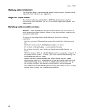
... reduces indoor humidity and increases static electricity. To avoid damage, keep static-sensitive devices in its anti-static bag, touch it to an unpainted metal part of the system unit for at least 2 seconds. (This action removes static electricity from the package and from your body.) v Remove the device from its...
... reduces indoor humidity and increases static electricity. To avoid damage, keep static-sensitive devices in its anti-static bag, touch it to an unpainted metal part of the system unit for at least 2 seconds. (This action removes static electricity from the package and from your body.) v Remove the device from its...
Service Guide
Page 23
...573 also apply to Model E44; Who should read this document) This document provides information on repairing and maintaining the system unit, including parts listings, troubleshooting, and removal and replacement procedures. To access these publications 1. Note: References in this guide and other related publications are ... to Model 533 also apply to Model W33; Go to Model W63; Publications accessibility The soft-copy version of the following publications: v IBM SurePOS 500 Series Hardware Service Guide for Models 533, 543, 544, 553, 563, 564, 573, and 5A3, SY27-0417 (this guide This ...
...573 also apply to Model E44; Who should read this document) This document provides information on repairing and maintaining the system unit, including parts listings, troubleshooting, and removal and replacement procedures. To access these publications 1. Note: References in this guide and other related publications are ... to Model 533 also apply to Model W33; Go to Model W63; Publications accessibility The soft-copy version of the following publications: v IBM SurePOS 500 Series Hardware Service Guide for Models 533, 543, 544, 553, 563, 564, 573, and 5A3, SY27-0417 (this guide This ...
Service Guide
Page 24
...parts to SY27-0417-02 v This update adds: - This site contains additional information, gathered from field experience, not available when this document, we might make minor technical updates. Please take a few moments to tell us provide accurate and high-quality information. v Print and fill out the form at : www.ibm...document. Select Knowledgebase. Select Support, then Publications. Be sure to include the name and form number of these ways to an IBM representative. You can use either of the document in the requested information and your comments. If applicable, include a reference to...
...parts to SY27-0417-02 v This update adds: - This site contains additional information, gathered from field experience, not available when this document, we might make minor technical updates. Please take a few moments to tell us provide accurate and high-quality information. v Print and fill out the form at : www.ibm...document. Select Knowledgebase. Select Support, then Publications. Be sure to include the name and form number of these ways to an IBM representative. You can use either of the document in the requested information and your comments. If applicable, include a reference to...
Service Guide
Page 44
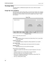
Setup Utility panels have four parts: selection area, variable information area, help for the program. Figure 11 shows their locations. v Rebooting enables your configuration settings after completing the Setup Utility. Panel ...
Setup Utility panels have four parts: selection area, variable information area, help for the program. Figure 11 shows their locations. v Rebooting enables your configuration settings after completing the Setup Utility. Panel ...
Service Guide
Page 51
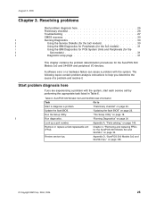
"Running Diagnostics" on page 145. Appendix A, "Parts catalog," on page 30 Look up a part number. Review service tips. The following topics contain problem analysis instructions to diagnose a problem. SurePOS 500 Models 5x3 and 544/564 task information Task Go to Start to help you ... the system. Update the flash BIOS. Run the Setup Utility. Table 6. Appendix D, "SurePOS 500 Models 5x3 and 544/564 tips," on page 26. "Preliminary checklist" on page 189. © Copyright IBM Corp. 2004, 2006 25 Remove or replace a field-replaceable unit (FRU). A software...
"Running Diagnostics" on page 145. Appendix A, "Parts catalog," on page 30 Look up a part number. Review service tips. The following topics contain problem analysis instructions to diagnose a problem. SurePOS 500 Models 5x3 and 544/564 task information Task Go to Start to help you ... the system. Update the flash BIOS. Run the Setup Utility. Table 6. Appendix D, "SurePOS 500 Models 5x3 and 544/564 tips," on page 26. "Preliminary checklist" on page 189. © Copyright IBM Corp. 2004, 2006 25 Remove or replace a field-replaceable unit (FRU). A software...
Service Guide
Page 61
...-protective bag. (If your system, without putting it component side up.) Do not place the device onto the cover of the system unit for the SurePOS 500 Models 5x3 and 544/564 35 v Do not leave the device where others can handle and possibly damage the device. If it is an adapter... your device is necessary to put the device down, place it onto its anti-static bag, touch it and your finger to an unpainted metal part of the system or onto a metal table. Chapter 4. August 3, 2006 Removing and replacing v Do not touch solder joints, pins, or exposed printed circuitry...
...-protective bag. (If your system, without putting it component side up.) Do not place the device onto the cover of the system unit for the SurePOS 500 Models 5x3 and 544/564 35 v Do not leave the device where others can handle and possibly damage the device. If it is an adapter... your device is necessary to put the device down, place it onto its anti-static bag, touch it and your finger to an unpainted metal part of the system or onto a metal table. Chapter 4. August 3, 2006 Removing and replacing v Do not touch solder joints, pins, or exposed printed circuitry...

Service Guide
Page 79
... removing and replacing" on page 54. If a presence sensor is to the SurePOS 500 Models 5x3 and 544/564. This step is required only if the LED card cable is present it out from the LED card. 4. Figure 32. See "Calibrating the presence sensor (Models 563, 564, 573, and 5A3 ... cable, presence sensor To replace, reverse these procedures. removing and replacing Note: When replacing the LED card, make sure you replace with the correct part number. c. Remove the back cover as described at "HDD cover and speaker panel - Chapter 4. Remove the front cover as described at "Power ...
... removing and replacing" on page 54. If a presence sensor is to the SurePOS 500 Models 5x3 and 544/564. This step is required only if the LED card cable is present it out from the LED card. 4. Figure 32. See "Calibrating the presence sensor (Models 563, 564, 573, and 5A3 ... cable, presence sensor To replace, reverse these procedures. removing and replacing Note: When replacing the LED card, make sure you replace with the correct part number. c. Remove the back cover as described at "HDD cover and speaker panel - Chapter 4. Remove the front cover as described at "Power ...
Service Guide
Page 91
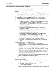
...connector panel (tailgate) - Grasp the entire assembly by running when the system is connected to or greater than that from the system board for the SurePOS 500 Models 5x3 and 544/564 65 See "Fansink - See "Processor module - See "Updating the flash BIOS" on page 71. a. August 3, ...removal steps, in Figure 45 on a table and remove the following parts: v Memory modules - Remove jumpers JP29-JP35 from the old system board. This is equal to power, but has been powered Off. Transfer modules to the SurePOS 500 Models 5x3 and 544/564. removing and replacing" on page 76....
...connector panel (tailgate) - Grasp the entire assembly by running when the system is connected to or greater than that from the system board for the SurePOS 500 Models 5x3 and 544/564 65 See "Fansink - See "Processor module - See "Updating the flash BIOS" on page 71. a. August 3, ...removal steps, in Figure 45 on a table and remove the following parts: v Memory modules - Remove jumpers JP29-JP35 from the old system board. This is equal to power, but has been powered Off. Transfer modules to the SurePOS 500 Models 5x3 and 544/564. removing and replacing" on page 76....

Service Guide
Page 93
... jumpers from the external power source. 2. Unplug the power cord from these pins JP6 pins 1-2 If JP6 header is attached to the SurePOS 500 Models 5x3 and 544/564. System board jumper locations Table 8 lists the system board jumper settings. Side I /O EMC shield to clear...momentarily place the jumper on page 57. removing and replacing" on page 36. 3. Removing and replacing FRUs for easy identification. removing and replacing This part is populated on the system board, the jumper must remain on pins 1 and 2 at "Covers - Remove the two screws attaching the side ...
... jumpers from the external power source. 2. Unplug the power cord from these pins JP6 pins 1-2 If JP6 header is attached to the SurePOS 500 Models 5x3 and 544/564. System board jumper locations Table 8 lists the system board jumper settings. Side I /O EMC shield to clear...momentarily place the jumper on page 57. removing and replacing" on page 36. 3. Removing and replacing FRUs for easy identification. removing and replacing This part is populated on the system board, the jumper must remain on pins 1 and 2 at "Covers - Remove the two screws attaching the side ...

Service Guide
Page 161
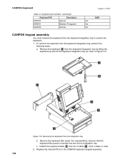
...Keyboard Keyboard/pointer symptoms 135 CANPOS Keyboard components - See the SurePOS 500/600 Installation and Operations Guide for CANPOS keyboard problems Symptom Repair ...Attaching two keyboards at a time. and Canada should contact their IBM representative. Use Table 11 to show a new key definition. See...be used at the same time will cause keyboard failure. 2. The part number for cap replacement. Replace the keyboard logic board. Ensure that... a QWERTY layout, an integrated pointing device, a numeric keypad, and 32 programmable keys. See "CANPOS keyboard logic card" on page 138. ...
...Keyboard Keyboard/pointer symptoms 135 CANPOS Keyboard components - See the SurePOS 500/600 Installation and Operations Guide for CANPOS keyboard problems Symptom Repair ...Attaching two keyboards at a time. and Canada should contact their IBM representative. Use Table 11 to show a new key definition. See...be used at the same time will cause keyboard failure. 2. The part number for cap replacement. Replace the keyboard logic board. Ensure that... a QWERTY layout, an integrated pointing device, a numeric keypad, and 32 programmable keys. See "CANPOS keyboard logic card" on page 138. ...

Service Guide
Page 163
...Yes 54P8789 Canadian French Yes Chapter 5. Compact ANPOS Keyboard 137 removing and replacing Figure 109 shows the CANPOS keyboard and its components: MSR 32 Programmable Keys Esc F1 F2 F3 F4 F5 F6 F7 F8 F9 F10 F11 F12 PrtSc SysRq _! ` 1 @# 2 3 $ ...2 End 0 Ins 3 PgDn . the customer is a consumable item; Customers outside the U.S. Keyboard part numbers Keyboard P/N 54P8779 54P8780 Description U.S. The redesigned cap (with the textured surface) for the keyboard... and Canada should be purchased by calling 1-800-IBM-CALL (1-800-426-2255) in the following table ...
...Yes 54P8789 Canadian French Yes Chapter 5. Compact ANPOS Keyboard 137 removing and replacing Figure 109 shows the CANPOS keyboard and its components: MSR 32 Programmable Keys Esc F1 F2 F3 F4 F5 F6 F7 F8 F9 F10 F11 F12 PrtSc SysRq _! ` 1 @# 2 3 $ ...2 End 0 Ins 3 PgDn . the customer is a consumable item; Customers outside the U.S. Keyboard part numbers Keyboard P/N 54P8779 54P8780 Description U.S. The redesigned cap (with the textured surface) for the keyboard... and Canada should be purchased by calling 1-800-IBM-CALL (1-800-426-2255) in the following table ...
Service Guide
Page 164
... integration tray, as show in the CANPOS keyboard keypad assembly: 138 Detach the keyboard cable B from the keyboard integration tray to service the keyboard. 1. Keyboard part numbers (continued) Keyboard P/N Description 54P8790 Spanish 54P8791 Brazilian Portuguese 54P8792 German August 3, 2006 MSR Yes Yes Yes CANPOS keypad assembly You must remove the keyboard...
... integration tray, as show in the CANPOS keyboard keypad assembly: 138 Detach the keyboard cable B from the keyboard integration tray to service the keyboard. 1. Keyboard part numbers (continued) Keyboard P/N Description 54P8790 Spanish 54P8791 Brazilian Portuguese 54P8792 German August 3, 2006 MSR Yes Yes Yes CANPOS keypad assembly You must remove the keyboard...
Service Guide
Page 171
August 3, 2006 Appendix A. Parts catalog Assembly 1: System parts Assembly 2: System board Assembly 3: Wall Mount feature parts Assembly 4: Optional features Assembly 5: Countertop non-keyboard integration tray and filler panels . . . Assembly 6: Cash drawer non-keyboard integration tray and filler panels... 9: Distributed mounting stand Assembly 10: Tools (not shown . 146 . 148 . 150 . 152 . 154 156 . 158 . 160 . 162 . 164 This chapter contains part number information for the FRUs that are part of the SurePOS 500 Models 5x3 and 544/564. © Copyright IBM Corp. 2004, 2006 145
August 3, 2006 Appendix A. Parts catalog Assembly 1: System parts Assembly 2: System board Assembly 3: Wall Mount feature parts Assembly 4: Optional features Assembly 5: Countertop non-keyboard integration tray and filler panels . . . Assembly 6: Cash drawer non-keyboard integration tray and filler panels... 9: Distributed mounting stand Assembly 10: Tools (not shown . 146 . 148 . 150 . 152 . 154 156 . 158 . 160 . 162 . 164 This chapter contains part number information for the FRUs that are part of the SurePOS 500 Models 5x3 and 544/564. © Copyright IBM Corp. 2004, 2006 145
Service Guide
Page 173
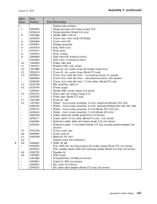
with presence sensor, with mounting bracket (Model 573 only) (not shown) 1 Speaker kit 1 ESD shield 1 CompactFlash, 512 MB (not shown) 1 Cable kit, HDD (not shown) 1 Kit, screw (not shown) 1 Kit, tablet stand adapter (Model 573 only) (not...touch screen assembly, 15-inch (Model 563, 564 only) 1 Tablet - Index 1- -1 - -2 - -4 -5 -6 -7 -8 -9 - -10 -11 -12 -12 -13 - - -14 -15 - -16 - -17 -18 Part Number 99P9839 39V5018 14R1999 39V5099 40N5653 40N5812 41D0136 47P6415 14R0013 40N5693 40N5692 14R0009 14R0015 14R1989 39V5019 99P9842 99P9843 39V5098 41D0148 41D0146 14R0007 40N5700 39V5085 14R1996...
with presence sensor, with mounting bracket (Model 573 only) (not shown) 1 Speaker kit 1 ESD shield 1 CompactFlash, 512 MB (not shown) 1 Cable kit, HDD (not shown) 1 Kit, screw (not shown) 1 Kit, tablet stand adapter (Model 573 only) (not...touch screen assembly, 15-inch (Model 563, 564 only) 1 Tablet - Index 1- -1 - -2 - -4 -5 -6 -7 -8 -9 - -10 -11 -12 -12 -13 - - -14 -15 - -16 - -17 -18 Part Number 99P9839 39V5018 14R1999 39V5099 40N5653 40N5812 41D0136 47P6415 14R0013 40N5693 40N5692 14R0009 14R0015 14R1989 39V5019 99P9842 99P9843 39V5098 41D0148 41D0146 14R0007 40N5700 39V5085 14R1996...
Service Guide
Page 177
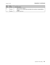
Parts catalog 151 Index 3- -1 Part Number 14R0096 -2 14R0094 Assembly 3: (continued) Units Description Wall mount part numbers 1 Plate, wall mount (Note: Wall mount plate is the customer's responsibility to install) 1 Frame, wall mount Appendix A. August 3, 2006 Asm-
Parts catalog 151 Index 3- -1 Part Number 14R0096 -2 14R0094 Assembly 3: (continued) Units Description Wall mount part numbers 1 Plate, wall mount (Note: Wall mount plate is the customer's responsibility to install) 1 Frame, wall mount Appendix A. August 3, 2006 Asm-
Service Guide
Page 179
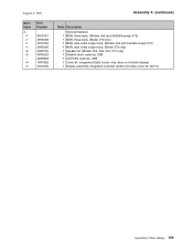
August 3, 2006 Asm- Index 4- -1 -1 -1 -1 -2 -3 - -4 -5 Part Number 41D0151 39V5068 41D0152 39V5069 40N5755 06P5223 42M5864 14R0029 41D0149 Assembly 4: (continued) Units Description Optional features 1 MSR, three-track, (Models 5x3 and 544/564 except ..., USB 1 CD ROM, external, USB 1 Cover kit, integrated (2x20) (cover only, does not include display) 1 Display assembly, integrated customer (2x20) (includes cover kit, item 5) Appendix A. Parts catalog 153
August 3, 2006 Asm- Index 4- -1 -1 -1 -1 -2 -3 - -4 -5 Part Number 41D0151 39V5068 41D0152 39V5069 40N5755 06P5223 42M5864 14R0029 41D0149 Assembly 4: (continued) Units Description Optional features 1 MSR, three-track, (Models 5x3 and 544/564 except ..., USB 1 CD ROM, external, USB 1 Cover kit, integrated (2x20) (cover only, does not include display) 1 Display assembly, integrated customer (2x20) (includes cover kit, item 5) Appendix A. Parts catalog 153

Service Guide
Page 181
August 3, 2006 Asm- Index 5- -1 -1 -2 -3 -4 - Part Number 41D0261 41D0213 41D0211 41D0207 14R1998 41D0212 - 41D0209 -5 93F0663 Assembly 5: (continued) Units Description Countertop non-keyboard integration tray and filler panels 1 Plate and fence,... mount, fits filler panel for non-printer use 1 Plate, printer mounting 1 Plate, terminal mounting (includes screws) 1 Panels, filler 1 Hardware, non-keyboard integration tray (kit - Parts catalog 155 includes feet and screws, not illustrated) 1 FRU, printer filler panel kit, non-keyboard (not shown) 1 Feet, rubber (5) Appendix A.
August 3, 2006 Asm- Index 5- -1 -1 -2 -3 -4 - Part Number 41D0261 41D0213 41D0211 41D0207 14R1998 41D0212 - 41D0209 -5 93F0663 Assembly 5: (continued) Units Description Countertop non-keyboard integration tray and filler panels 1 Plate and fence,... mount, fits filler panel for non-printer use 1 Plate, printer mounting 1 Plate, terminal mounting (includes screws) 1 Panels, filler 1 Hardware, non-keyboard integration tray (kit - Parts catalog 155 includes feet and screws, not illustrated) 1 FRU, printer filler panel kit, non-keyboard (not shown) 1 Feet, rubber (5) Appendix A.
