Owner's Manual
Page 8
... the Power Supply 152 I/O Panel 153 Removing the I/O Panel 154 Installing the I/O Panel 155 Processor Fan 155 Removing the Processor Fan/Heat Sink Assembly 156 Installing the Processor Fan/Heat Sink Assembly 157 Processor 158 Removing the Processor 158 Installing the Processor 159 Chassis Fan 162 Removing the Chassis Fan 162 Replacing the Chassis Fan 163...
... the Power Supply 152 I/O Panel 153 Removing the I/O Panel 154 Installing the I/O Panel 155 Processor Fan 155 Removing the Processor Fan/Heat Sink Assembly 156 Installing the Processor Fan/Heat Sink Assembly 157 Processor 158 Removing the Processor 158 Installing the Processor 159 Chassis Fan 162 Removing the Chassis Fan 162 Replacing the Chassis Fan 163...
Owner's Manual
Page 41
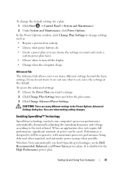
...when to the task at the default. Use care when making setting changes. Enabling SpeedStep™ Technology SpeedStep technology controls your computer's processor performance automatically, dynamically adjusting the operating frequency and voltage, according to turn off the display. • Change when the computer sleeps. ...3 Click Change Advanced Power Settings. In the Power Options window, click Change Plan Settings to set many different settings in the Dell Recommended, Balanced, and Power Saver power plans. CAUTION: There are not sure what power buttons do not know or are many...
...when to the task at the default. Use care when making setting changes. Enabling SpeedStep™ Technology SpeedStep technology controls your computer's processor performance automatically, dynamically adjusting the operating frequency and voltage, according to turn off the display. • Change when the computer sleeps. ...3 Click Change Advanced Power Settings. In the Power Options window, click Change Plan Settings to set many different settings in the Dell Recommended, Balanced, and Power Saver power plans. CAUTION: There are not sure what power buttons do not know or are many...
Owner's Manual
Page 84
... IN RESOLVING THIS PROBLEM, PLEASE NOTE T H I S C H E C K P O I N T A N D C O N T A C T D E L L TE C H N I L U R E - H A R D - Replace CPU fan. See "Removing the Processor Fan/Heat Sink Assembly" on page 66. 84 Troubleshooting Tools PREVIOUS ATTEMPTS AT BOOTING THIS SYSTEM HAVE FAILED AT CHECKPOINT [NNNN]. See "Contacting Dell" on page 187 for loose cable connection. ALERT! Possible motherboard failure or RTC battery...
... IN RESOLVING THIS PROBLEM, PLEASE NOTE T H I S C H E C K P O I N T A N D C O N T A C T D E L L TE C H N I L U R E - H A R D - Replace CPU fan. See "Removing the Processor Fan/Heat Sink Assembly" on page 66. 84 Troubleshooting Tools PREVIOUS ATTEMPTS AT BOOTING THIS SYSTEM HAVE FAILED AT CHECKPOINT [NNNN]. See "Contacting Dell" on page 187 for loose cable connection. ALERT! Possible motherboard failure or RTC battery...

Owner's Manual
Page 102
.... 3 Ensure that the computer and any of the procedures in this type of cable, press in the Product Information Guide. Hold a component such as a processor by its edges, not by its pins. Turning Off Your Computer NOTICE: To avoid losing data, save and close all open files and exit all... open programs before you turn off when you connect a cable, ensure that is not authorized by Dell is not covered by your warranty. NOTICE: Handle components and cards with locking tabs; As you are correctly oriented and aligned. 102 Removing and Installing...
.... 3 Ensure that the computer and any of the procedures in this type of cable, press in the Product Information Guide. Hold a component such as a processor by its edges, not by its pins. Turning Off Your Computer NOTICE: To avoid losing data, save and close all open files and exit all... open programs before you turn off when you connect a cable, ensure that is not authorized by Dell is not covered by your warranty. NOTICE: Handle components and cards with locking tabs; As you are correctly oriented and aligned. 102 Removing and Installing...
Owner's Manual
Page 106
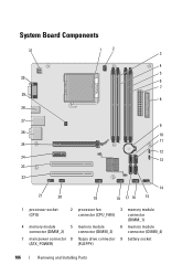
System Board Components 31 30 29 28 1 2 3 4 5 6 7 8 27 9 26 10 11 25 12 24 13 23 22 21 20 14 19 18 17 16 15 1 processor socket (CPU) 2 processor fan connector (CPU_FAN) 3 memory module connector (DIMM_1) 4 memory module 5 memory module 6 memory module connector (DIMM_2) connector (DIMM_3) connector (DIMM_4) 7 main power connector 8 floppy drive connector 9 battery socket (ATX_POWER) (FLOPPY) 106 Removing and Installing Parts
System Board Components 31 30 29 28 1 2 3 4 5 6 7 8 27 9 26 10 11 25 12 24 13 23 22 21 20 14 19 18 17 16 15 1 processor socket (CPU) 2 processor fan connector (CPU_FAN) 3 memory module connector (DIMM_1) 4 memory module 5 memory module 6 memory module connector (DIMM_2) connector (DIMM_3) connector (DIMM_4) 7 main power connector 8 floppy drive connector 9 battery socket (ATX_POWER) (FLOPPY) 106 Removing and Installing Parts
Owner's Manual
Page 155
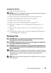
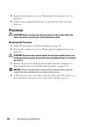
.... 5 Replace the bezel (see "Replacing the Bezel" on page 125). 6 Replace the computer cover (see "Dell Diagnostics" on page 86). You can do so by running the Dell Diagnostics (see "Replacing the Computer Cover" on page 166). 7 Connect your computer and devices to components inside your...on. 8 Verify that the computer works correctly by touching an unpainted metal surface on the computer chassis. Removing and Installing Parts 155 Processor Fan CAUTION: Before you touch any of your computer, discharge static electricity from the electrical outlet before you begin any of the ...
.... 5 Replace the bezel (see "Replacing the Bezel" on page 125). 6 Replace the computer cover (see "Dell Diagnostics" on page 86). You can do so by running the Dell Diagnostics (see "Replacing the Computer Cover" on page 166). 7 Connect your computer and devices to components inside your...on. 8 Verify that the computer works correctly by touching an unpainted metal surface on the computer chassis. Removing and Installing Parts 155 Processor Fan CAUTION: Before you touch any of your computer, discharge static electricity from the electrical outlet before you begin any of the ...
Owner's Manual
Page 156
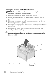
... in "Before You Begin" on page 101. 2 Remove the computer cover (see "Removing the Computer Cover" on page 103). 3 Disconnect the processor fan cable from the system board (see "System Board Components" on page 106). 4 Carefully move away any cables that it has had sufficient time... to cool before you are routed over the processor fan/heat sink assembly. 5 Loosen the four captive screws securing the processor fan/heat sink assembly and lift it . 1 2 1 captive screws (4) 2 processor fan/heat sink assembly 156 Removing and Installing Parts CAUTION: Despite having ...
... in "Before You Begin" on page 101. 2 Remove the computer cover (see "Removing the Computer Cover" on page 103). 3 Disconnect the processor fan cable from the system board (see "System Board Components" on page 106). 4 Carefully move away any cables that it has had sufficient time... to cool before you are routed over the processor fan/heat sink assembly. 5 Loosen the four captive screws securing the processor fan/heat sink assembly and lift it . 1 2 1 captive screws (4) 2 processor fan/heat sink assembly 156 Removing and Installing Parts CAUTION: Despite having ...
Owner's Manual
Page 157
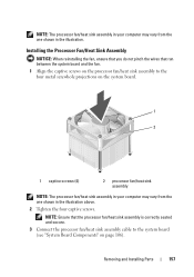
...and the fan. 1 Align the captive screws on the processor fan/heat sink assembly to the system board (see "System Board Components" on the system board. 1 2 1 captive screws (4) 2 processor fan/heat sink assembly NOTE: The processor fan/heat sink assembly in your computer may vary from ...the one shown in the illustration. NOTE: The processor fan/heat sink assembly in your computer may vary from the one shown...
...and the fan. 1 Align the captive screws on the processor fan/heat sink assembly to the system board (see "System Board Components" on the system board. 1 2 1 captive screws (4) 2 processor fan/heat sink assembly NOTE: The processor fan/heat sink assembly in your computer may vary from ...the one shown in the illustration. NOTE: The processor fan/heat sink assembly in your computer may vary from the one shown...
Owner's Manual
Page 158
... your finger upon the hook end of the release lever, then push down and out to release it from the computer (see "Removing the Processor Fan/Heat Sink Assembly" on page 156). CAUTION: Despite having a plastic shield, the heat sink assembly may be very hot during normal operation.... Removing the Processor 1 Follow the procedures in the Product Information Guide. Be sure that secures it . 3 Remove the processor fan/heat sink assembly from the tab that it has had sufficient time to an electrical outlet...
... your finger upon the hook end of the release lever, then push down and out to release it from the computer (see "Removing the Processor Fan/Heat Sink Assembly" on page 156). CAUTION: Despite having a plastic shield, the heat sink assembly may be very hot during normal operation.... Removing the Processor 1 Follow the procedures in the Product Information Guide. Be sure that secures it . 3 Remove the processor fan/heat sink assembly from the tab that it has had sufficient time to an electrical outlet...
Owner's Manual
Page 159
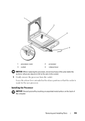
1 2 3 4 1 processor cover 3 socket 2 processor 4 release lever NOTICE: When replacing the processor, do not touch any objects to fall on the pins in the release position so that the socket is ready for the new processor. Removing and Installing Parts 159 Installing the Processor NOTICE: Ground yourself by touching an unpainted metal surface on the back of the pins inside the socket or allow any of the computer. Leave the release lever extended in the socket. 5 Gently remove the processor from the socket.
1 2 3 4 1 processor cover 3 socket 2 processor 4 release lever NOTICE: When replacing the processor, do not touch any objects to fall on the pins in the release position so that the socket is ready for the new processor. Removing and Installing Parts 159 Installing the Processor NOTICE: Ground yourself by touching an unpainted metal surface on the back of the pins inside the socket or allow any of the computer. Leave the release lever extended in the socket. 5 Gently remove the processor from the socket.

Owner's Manual
Page 160
...on the socket is positioned underneath the center cover latch on the socket. 5 Align the pin-1 corners of the processor. NOTICE: To avoid damage, ensure that the processor aligns properly with the front and rear alignment-notches on the socket. 8 Pivot the socket release lever back toward ... to avoid permanent damage to secure the processor. 160 Removing and Installing Parts Ensure that the tab on the processor cover is not fully extended, move it into place to the processor and the computer when you install the processor. 6 Set the processor lightly in the socket and ensure that ...
...on the socket is positioned underneath the center cover latch on the socket. 5 Align the pin-1 corners of the processor. NOTICE: To avoid damage, ensure that the processor aligns properly with the front and rear alignment-notches on the socket. 8 Pivot the socket release lever back toward ... to avoid permanent damage to secure the processor. 160 Removing and Installing Parts Ensure that the tab on the processor cover is not fully extended, move it into place to the processor and the computer when you install the processor. 6 Set the processor lightly in the socket and ensure that ...

Owner's Manual
Page 161
... the new thermal grease to the top of the heat sink. 2 1 9 3 4 5 6 8 7 1 processor cover 4 processor socket 7 front alignment-notch 2 tab 5 center cover latch 8 processor pin-1 indicator 3 processor 6 release lever 9 rear alignment notch 9 Clean the thermal grease from the bottom of the processor. 11 Install the processor fan/heat sink assembly (see "Replacing the Computer Cover" on page...
... the new thermal grease to the top of the heat sink. 2 1 9 3 4 5 6 8 7 1 processor cover 4 processor socket 7 front alignment-notch 2 tab 5 center cover latch 8 processor pin-1 indicator 3 processor 6 release lever 9 rear alignment notch 9 Clean the thermal grease from the bottom of the processor. 11 Install the processor fan/heat sink assembly (see "Replacing the Computer Cover" on page...
Owner's Manual
Page 164
... assembly, power supply, and other components may be installed in cards on the system board (see "Cards" on page 115). 4 Remove the processor and heat sink assembly (see "Removing the Processor Fan/Heat Sink Assembly" on page 156). 5 Remove the memory modules (see "Removing Memory" on page 115) and document which memory...
... assembly, power supply, and other components may be installed in cards on the system board (see "Cards" on page 115). 4 Remove the processor and heat sink assembly (see "Removing the Processor Fan/Heat Sink Assembly" on page 156). 5 Remove the memory modules (see "Removing Memory" on page 115) and document which memory...
Owner's Manual
Page 166
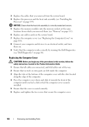
... 166). 8 Connect your computer and devices to an electrical outlet, and turn them on. 9 Verify that the computer works correctly by running the Dell Diagnostics (see "Installing the Processor" on page 86). Replacing the Computer Cover CAUTION: Before you feel a click or feel the computer cover securely installed. 5 Ensure that secure the... the cover is correctly seated and secure. 5 Replace the memory modules into the memory sockets at the same locations from the system board. 4 Replace the processor and the heat sink assembly (see "Dell Diagnostics" on page 159).
... 166). 8 Connect your computer and devices to an electrical outlet, and turn them on. 9 Verify that the computer works correctly by running the Dell Diagnostics (see "Installing the Processor" on page 86). Replacing the Computer Cover CAUTION: Before you feel a click or feel the computer cover securely installed. 5 Ensure that secure the... the cover is correctly seated and secure. 5 Replace the memory modules into the memory sockets at the same locations from the system board. 4 Replace the processor and the heat sink assembly (see "Dell Diagnostics" on page 159).

Owner's Manual
Page 169
... Computer Information Chipset RAID Support DMA channels Interrupt levels BIOS chip (NVRAM) NIC Video Type Intel® Core™ 2 Duo processor Intel® Pentium® Dual-Core processor Intel® Celeron® processor At least 512 KB pipelined-burst, eight-way set associative, writeback SRAM 667-MHz, 800-MHz DDR2 SDRAM four 512...
... Computer Information Chipset RAID Support DMA channels Interrupt levels BIOS chip (NVRAM) NIC Video Type Intel® Core™ 2 Duo processor Intel® Pentium® Dual-Core processor Intel® Celeron® processor At least 512 KB pipelined-burst, eight-way set associative, writeback SRAM 667-MHz, 800-MHz DDR2 SDRAM four 512...
Owner's Manual
Page 171
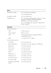
Drives Externally accessible: Internally accessible Available devices Connectors External connectors: Video Network adapter USB Audio System board connectors: Serial ATA Internal USB device Floppy drive Processor fan Chassis fan PCI 2.3 PCI Express x1 PCI Express x16 Front panel control Front panel USB Front panel audio HDA header one 3.5-inch drive bay (...
Drives Externally accessible: Internally accessible Available devices Connectors External connectors: Video Network adapter USB Audio System board connectors: Serial ATA Internal USB device Floppy drive Processor fan Chassis fan PCI 2.3 PCI Express x1 PCI Express x16 Front panel control Front panel USB Front panel audio HDA header one 3.5-inch drive bay (...
Owner's Manual
Page 172
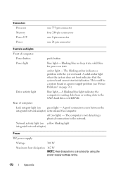
Connectors Processor Memory Power 12V Power one 775-pin connector four 240-pin connectors one 4-pin connector one 24-pin connector Controls and Lights Front of computer: ...
Connectors Processor Memory Power 12V Power one 775-pin connector four 240-pin connectors one 4-pin connector one 24-pin connector Controls and Lights Front of computer: ...
Owner's Manual
Page 176
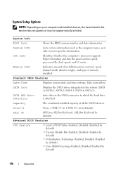
... (Disabled by default) • Core Multi-Processing-Enabled; Disabled (Enabled by default) 176 Appendix SATA-4; CPU Info Identifies whether the computer's processor supports Hyper-Threading and lists the processor bus speed, processor ID, clock speed, and L2 cache. Halt On All Error; System Info Lists system information such as listed. Date (mm:dd...
... (Disabled by default) • Core Multi-Processing-Enabled; Disabled (Enabled by default) 176 Appendix SATA-4; CPU Info Identifies whether the computer's processor supports Hyper-Threading and lists the processor bus speed, processor ID, clock speed, and L2 cache. Halt On All Error; System Info Lists system information such as listed. Date (mm:dd...
Owner's Manual
Page 190
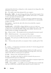
...erased or written over. 190 Glossary Celsius - A special high-speed storage mechanism which the computer attempts to the processor or incorporated into foreign countries. carnet - An international customs document that allows for measuring data transmission speed. Data can...computer. byte - A wireless technology standard for short-range (9 m [29 feet]) networking devices that facilitates temporary imports into the processor architecture. bootable media - British thermal unit - bus - A communication pathway between the components in MHz, that you can transfer ...
...erased or written over. 190 Glossary Celsius - A special high-speed storage mechanism which the computer attempts to the processor or incorporated into foreign countries. carnet - An international customs document that allows for measuring data transmission speed. Data can...computer. byte - A wireless technology standard for short-range (9 m [29 feet]) networking devices that facilitates temporary imports into the processor architecture. bootable media - British thermal unit - bus - A communication pathway between the components in MHz, that you can transfer ...
Owner's Manual
Page 191
... to modify operating system and hardware settings, such as the Product Key or Product ID. Computers use a small amount of data between the processor and memory or between the processor and devices. double-data-rate 2 SDRAM - See driver. You can write to CD-RW discs multiple times, but you to hold date...
... to modify operating system and hardware settings, such as the Product Key or Product ID. Computers use a small amount of data between the processor and memory or between the processor and devices. double-data-rate 2 SDRAM - See driver. You can write to CD-RW discs multiple times, but you to hold date...


