Owner's Manual
Page 7
... Off Your Computer 102 Before Working Inside Your Computer 102 Removing the Computer Cover 103 Inside View of Your Computer 105 System Board Components 106 Power Supply DC Connector Pin Assignments . . . . . 108 Memory 111 Memory Installation Guidelines 112 Installing Memory 113 Removing Memory 115 Cards 115 PCI and PCI Express Cards 116...
... Off Your Computer 102 Before Working Inside Your Computer 102 Removing the Computer Cover 103 Inside View of Your Computer 105 System Board Components 106 Power Supply DC Connector Pin Assignments . . . . . 108 Memory 111 Memory Installation Guidelines 112 Installing Memory 113 Removing Memory 115 Cards 115 PCI and PCI Express Cards 116...
Owner's Manual
Page 8
Battery 150 Replacing the Battery 150 Power Supply 151 Replacing the Power Supply 152 I/O Panel 153 Removing the I/O Panel 154 Installing the I/O Panel 155 Processor Fan 155 Removing the Processor Fan/Heat Sink Assembly 156 Installing the Processor ...
Battery 150 Replacing the Battery 150 Power Supply 151 Replacing the Power Supply 152 I/O Panel 153 Removing the I/O Panel 154 Installing the I/O Panel 155 Processor Fan 155 Removing the Processor Fan/Heat Sink Assembly 156 Installing the Processor ...
Owner's Manual
Page 18
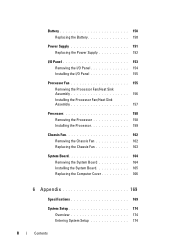
Plug USB, audio, and other devices into the appropriate connector. See "Back Panel Connectors" on page 20 for power supply. Back View of the Computer 1 2 3 7 4 6 5 1 power connector 2 voltage selector switch 3 power supply LED 4 back panel connectors Insert the power cable. Used to select voltage rating. Indicates power availability for more information. 18 Setting Up and Using Your Computer
Plug USB, audio, and other devices into the appropriate connector. See "Back Panel Connectors" on page 20 for power supply. Back View of the Computer 1 2 3 7 4 6 5 1 power connector 2 voltage selector switch 3 power supply LED 4 back panel connectors Insert the power cable. Used to select voltage rating. Indicates power availability for more information. 18 Setting Up and Using Your Computer
Owner's Manual
Page 105
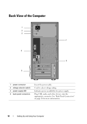
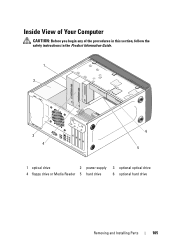
Inside View of Your Computer CAUTION: Before you begin any of the procedures in this section, follow the safety instructions in the Product Information Guide. 1 2 3 4 6 5 1 optical drive 2 power supply 3 optional optical drive 4 floppy drive or Media Reader 5 hard drive 6 optional hard drive Removing and Installing Parts 105
Inside View of Your Computer CAUTION: Before you begin any of the procedures in this section, follow the safety instructions in the Product Information Guide. 1 2 3 4 6 5 1 optical drive 2 power supply 3 optional optical drive 4 floppy drive or Media Reader 5 hard drive 6 optional hard drive Removing and Installing Parts 105
Owner's Manual
Page 108
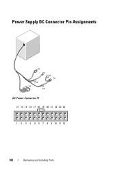
Power Supply DC Connector Pin Assignments DC Power Connector P1 13 14 15 16 17 18 19 20 21 22 23 24 1 2 3 4 5 6 7 8 9 10 11 12 108 Removing and Installing Parts
Power Supply DC Connector Pin Assignments DC Power Connector P1 13 14 15 16 17 18 19 20 21 22 23 24 1 2 3 4 5 6 7 8 9 10 11 12 108 Removing and Installing Parts
Owner's Manual
Page 151
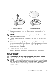
... other errors associated with the battery replacement in the Event Log. 10 Properly dispose of your body before you begin any of the old battery. Power Supply CAUTION: Before you touch any of the procedures in this section, follow the safety instructions located in Step 1. Then go to components inside your computer...
... other errors associated with the battery replacement in the Event Log. 10 Properly dispose of your body before you begin any of the old battery. Power Supply CAUTION: Before you touch any of the procedures in this section, follow the safety instructions located in Step 1. Then go to components inside your computer...
Owner's Manual
Page 152
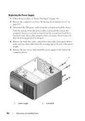
... Note the routing of the DC power cables underneath the tabs in "Before You Begin" on page 101. 2 Remove the computer cover (see "Removing the Computer Cover" on the side of the power supply. 5 Remove the four screws that attach the power supply to prevent them from the system ...board and the drives. Replacing the Power Supply 1 Follow the procedures in the computer chassis as you replace them to the back...
... Note the routing of the DC power cables underneath the tabs in "Before You Begin" on page 101. 2 Remove the computer cover (see "Removing the Computer Cover" on the side of the power supply. 5 Remove the four screws that attach the power supply to prevent them from the system ...board and the drives. Replacing the Power Supply 1 Follow the procedures in the computer chassis as you replace them to the back...
Owner's Manual
Page 153
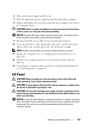
...chassis. CAUTION: The heat sink assembly, power supply, and other components may cause electrical shock as these screws are secure. 11 Replace the computer cover (see "Dell Diagnostics" on the computer chassis. You can do so by running the Dell Diagnostics (see "Replacing the Computer Cover..." on the side of the power supply. Removing and Installing Parts 153 NOTICE: Route the DC power cables under the chassis tabs. ...
...chassis. CAUTION: The heat sink assembly, power supply, and other components may cause electrical shock as these screws are secure. 11 Replace the computer cover (see "Dell Diagnostics" on the computer chassis. You can do so by running the Dell Diagnostics (see "Replacing the Computer Cover..." on the side of the power supply. Removing and Installing Parts 153 NOTICE: Route the DC power cables under the chassis tabs. ...
Owner's Manual
Page 155
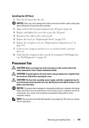
CAUTION: The heat sink assembly, power supply, and other components may be very hot during normal operation. ... this section, follow the safety instructions in the Product Information Guide. You can do so by running the Dell Diagnostics (see "Replacing the Computer Cover" on page 166). 7 Connect your body before opening the cover....system board. 5 Replace the bezel (see "Replacing the Bezel" on page 125). 6 Replace the computer cover (see "Dell Diagnostics" on the computer chassis. Do not try to components inside your computer, discharge static electricity from the electrical outlet before...
CAUTION: The heat sink assembly, power supply, and other components may be very hot during normal operation. ... this section, follow the safety instructions in the Product Information Guide. You can do so by running the Dell Diagnostics (see "Replacing the Computer Cover" on page 166). 7 Connect your body before opening the cover....system board. 5 Replace the bezel (see "Replacing the Bezel" on page 125). 6 Replace the computer cover (see "Dell Diagnostics" on the computer chassis. Do not try to components inside your computer, discharge static electricity from the electrical outlet before...
Owner's Manual
Page 162
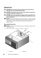
... opening the cover. Be sure that they have had sufficient time to components inside your body before you touch them. CAUTION: The heat sink assembly, power supply, and other components may be very hot during normal operation. You can do so by touching an unpainted metal surface on page 101 1 2 1 screws (4) 2 chassis...
... opening the cover. Be sure that they have had sufficient time to components inside your body before you touch them. CAUTION: The heat sink assembly, power supply, and other components may be very hot during normal operation. You can do so by touching an unpainted metal surface on page 101 1 2 1 screws (4) 2 chassis...
Owner's Manual
Page 164
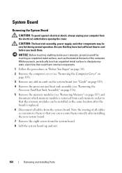
... an unpainted metal surface to cool before opening the cover. Be sure that the memory modules can re-route them . CAUTION: The heat sink assembly, power supply, and other components may be installed in cards on the system board (see "Cards" on page 115). 4 Remove the processor and heat sink assembly (see...
... an unpainted metal surface to cool before opening the cover. Be sure that the memory modules can re-route them . CAUTION: The heat sink assembly, power supply, and other components may be installed in cards on the system board (see "Cards" on page 115). 4 Remove the processor and heat sink assembly (see...
Owner's Manual
Page 172
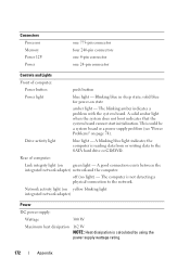
... not boot indicates that the system board cannot start initialization. Network activity light (on yellow blinking light integrated network adapter) Power DC power supply: Wattage 300 W Maximum heat dissipation 162 W NOTE: Heat dissipation is not detecting a physical connection to the SATA hard... Drive activity light blue light - Rear of computer: Power button push button Power light blue light - The computer is calculated by using the power supply wattage rating. 172 Appendix Connectors Processor Memory Power 12V Power one 775-pin connector four 240-pin connectors one 4-pin...
... not boot indicates that the system board cannot start initialization. Network activity light (on yellow blinking light integrated network adapter) Power DC power supply: Wattage 300 W Maximum heat dissipation 162 W NOTE: Heat dissipation is not detecting a physical connection to the SATA hard... Drive activity light blue light - Rear of computer: Power button push button Power light blue light - The computer is calculated by using the power supply wattage rating. 172 Appendix Connectors Processor Memory Power 12V Power one 775-pin connector four 240-pin connectors one 4-pin...
Owner's Manual
Page 203
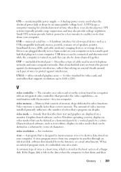
...an infected program starts, its embedded virus also starts. If the floppy disk is turned on your computer. video memory - A backup power source used in the drive when the computer is stored in video modes that can be defined as x horizontal pixels by y vertical pixels...boot sectors of unshielded wires are twisted to protect against interference. A virus program moves from the Internet, or e-mail attachments. uninterruptible power supply - Devices are displayed on the system board (in combination with the monitor-for a few minutes to enable you or to protect ...
...an infected program starts, its embedded virus also starts. If the floppy disk is turned on your computer. video memory - A backup power source used in the drive when the computer is stored in video modes that can be defined as x horizontal pixels by y vertical pixels...boot sectors of unshielded wires are twisted to protect against interference. A virus program moves from the Internet, or e-mail attachments. uninterruptible power supply - Devices are displayed on the system board (in combination with the monitor-for a few minutes to enable you or to protect ...
Owner's Manual
Page 204
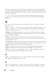
... scan in that communicate with no stress applied to either the chip or its write-protect tab to be changed or destroyed. You can supply 66 W of power for 1 hour or 33 W for video cards and controllers that supports resolutions up to protect data from being changed . A series of ...all the floppy disks that are read or written in your wallpaper through that allows a computer chip to the open position. The measurement of electrical power. watt-hour - To write-protect a 3.5-inch floppy disk, slide its socket. 204 Glossary watt - wallpaper - Use write-protection when you want...
... scan in that communicate with no stress applied to either the chip or its write-protect tab to be changed or destroyed. You can supply 66 W of power for 1 hour or 33 W for video cards and controllers that supports resolutions up to protect data from being changed . A series of ...all the floppy disks that are read or written in your wallpaper through that allows a computer chip to the open position. The measurement of electrical power. watt-hour - To write-protect a 3.5-inch floppy disk, slide its socket. 204 Glossary watt - wallpaper - Use write-protection when you want...


