Owner's Manual
Page 7
... Inside View of Your Computer 105 System Board Components 106 Power Supply DC Connector Pin Assignments . . . . . 108 Memory 111 Memory Installation Guidelines 112 Installing Memory 113 Removing Memory 115 Cards 115 PCI and PCI Express Cards 116 Bezel 123 Removing the Bezel 123 Replacing the Bezel 125 Drives 126 Recommended Drive Cable Connections...
... Inside View of Your Computer 105 System Board Components 106 Power Supply DC Connector Pin Assignments . . . . . 108 Memory 111 Memory Installation Guidelines 112 Installing Memory 113 Removing Memory 115 Cards 115 PCI and PCI Express Cards 116 Bezel 123 Removing the Bezel 123 Replacing the Bezel 125 Drives 126 Recommended Drive Cable Connections...
Owner's Manual
Page 8
Battery 150 Replacing the Battery 150 Power Supply 151 Replacing the Power Supply 152 I/O Panel 153 Removing the I/O Panel 154 Installing the I/O Panel 155 Processor Fan 155 Removing the Processor Fan/Heat Sink Assembly 156 Installing the Processor ...
Battery 150 Replacing the Battery 150 Power Supply 151 Replacing the Power Supply 152 I/O Panel 153 Removing the I/O Panel 154 Installing the I/O Panel 155 Processor Fan 155 Removing the Processor Fan/Heat Sink Assembly 156 Installing the Processor ...
Owner's Manual
Page 151
Then go to the Maintenance section and clear the low battery and other errors associated with the battery replacement in the Event Log. 10 Properly dispose of the procedures in this section, follow the safety instructions located in Step 1. NOTICE: To ...computer's electronic components. NOTICE: To prevent static damage to electrical outlets, and then turn them on. 9 Enter system setup (see "Replacing the Computer Cover" on page 166). Power Supply CAUTION: Before you recorded in the Product Information Guide. You can do so by touching an unpainted metal surface on page 174...
Then go to the Maintenance section and clear the low battery and other errors associated with the battery replacement in the Event Log. 10 Properly dispose of the procedures in this section, follow the safety instructions located in Step 1. NOTICE: To ...computer's electronic components. NOTICE: To prevent static damage to electrical outlets, and then turn them on. 9 Enter system setup (see "Replacing the Computer Cover" on page 166). Power Supply CAUTION: Before you recorded in the Product Information Guide. You can do so by touching an unpainted metal surface on page 174...
Owner's Manual
Page 152
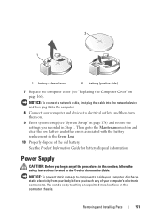
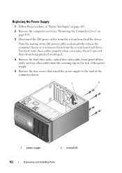
... the procedures in the computer chassis as you replace them to the back of the computer chassis. 1 2 1 power supply 2 screws (4) 152 Removing and Installing Parts You must route these cables properly when you remove them from being pinched or crimped. 4 Remove the hard drive... and drives. Note the routing of the DC power cables underneath the tabs in "Before You Begin" on page 101. 2 Remove the computer cover (see "Removing the Computer Cover" on the side of the power supply. 5 Remove the four screws that attach the power supply to prevent them from the system board and the...
... the procedures in the computer chassis as you replace them to the back of the computer chassis. 1 2 1 power supply 2 screws (4) 152 Removing and Installing Parts You must route these cables properly when you remove them from being pinched or crimped. 4 Remove the hard drive... and drives. Note the routing of the DC power cables underneath the tabs in "Before You Begin" on page 101. 2 Remove the computer cover (see "Removing the Computer Cover" on the side of the power supply. 5 Remove the four screws that attach the power supply to prevent them from the system board and the...
Owner's Manual
Page 153
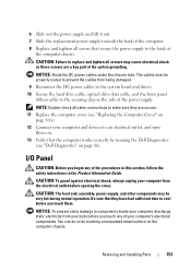
... do so by running the Dell Diagnostics (see "Replacing the Computer Cover" on page 86). The cables must be very hot during normal operation. 6 Slide out the power supply and lift it out. 7 Slide the replacement power supply towards the back of the computer. 8 Replace and tighten all screws may ... to the back of the computer chassis. CAUTION: The heat sink assembly, power supply, and other components may cause electrical shock as these screws are secure. 11 Replace the computer cover (see "Dell Diagnostics" on page 166). 12 Connect your computer and devices to components inside...
... do so by running the Dell Diagnostics (see "Replacing the Computer Cover" on page 86). The cables must be very hot during normal operation. 6 Slide out the power supply and lift it out. 7 Slide the replacement power supply towards the back of the computer. 8 Replace and tighten all screws may ... to the back of the computer chassis. CAUTION: The heat sink assembly, power supply, and other components may cause electrical shock as these screws are secure. 11 Replace the computer cover (see "Dell Diagnostics" on page 166). 12 Connect your computer and devices to components inside...
Owner's Manual
Page 155
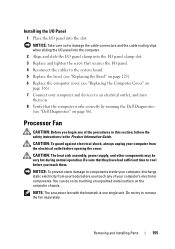
... to cool before opening the cover. You can do so by running the Dell Diagnostics (see "Replacing the Computer Cover" on page 166). 7 Connect your computer and devices to an electrical outlet, and turn them . CAUTION: The heat sink assembly, power supply, and other components may be very hot during normal operation. Installing the...
... to cool before opening the cover. You can do so by running the Dell Diagnostics (see "Replacing the Computer Cover" on page 166). 7 Connect your computer and devices to an electrical outlet, and turn them . CAUTION: The heat sink assembly, power supply, and other components may be very hot during normal operation. Installing the...
Owner's Manual
Page 164
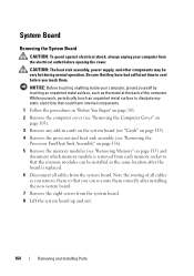
...system board up and out. 164 Removing and Installing Parts Be sure that the memory modules can re-route them . CAUTION: The heat sink assembly, power supply, and other components may be installed in cards on the system board (see "Cards" on page 115). 4 Remove the processor and heat sink assembly ...procedures in "Before You Begin" on page 101. 2 Remove the computer cover (see "Removing Memory" on page 115) and document which memory module is replaced. 6 Disconnect all cables as the metal at the back of all cables from each memory socket so that they have had sufficient time to cool...
...system board up and out. 164 Removing and Installing Parts Be sure that the memory modules can re-route them . CAUTION: The heat sink assembly, power supply, and other components may be installed in cards on the system board (see "Cards" on page 115). 4 Remove the processor and heat sink assembly ...procedures in "Before You Begin" on page 101. 2 Remove the computer cover (see "Removing Memory" on page 115) and document which memory module is replaced. 6 Disconnect all cables as the metal at the back of all cables from each memory socket so that they have had sufficient time to cool...


