Owner's Manual
Page 7
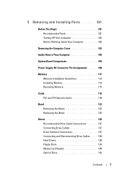
... Installation Guidelines 112 Installing Memory 113 Removing Memory 115 Cards 115 PCI and PCI Express Cards 116 Bezel 123 Removing the Bezel 123 Replacing the Bezel 125 Drives 126 Recommended Drive Cable Connections . . . . . 127 Connecting Drive Cables 127 Drive Interface Connectors 127 Connecting and Disconnecting Drive Cables . . . 128 Hard Drives 128 Floppy Drive 134 Media Card Reader 140 Optical...
... Installation Guidelines 112 Installing Memory 113 Removing Memory 115 Cards 115 PCI and PCI Express Cards 116 Bezel 123 Removing the Bezel 123 Replacing the Bezel 125 Drives 126 Recommended Drive Cable Connections . . . . . 127 Connecting Drive Cables 127 Drive Interface Connectors 127 Connecting and Disconnecting Drive Cables . . . 128 Hard Drives 128 Floppy Drive 134 Media Card Reader 140 Optical...
Owner's Manual
Page 43
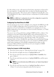
... Configuring Your Hard Drives for RAID if you did not select a RAID configuration when you begin. and down-arrow keys to configure your computer for RAID At some point you may want to highlight Drive Controller, then press . 4 Press the up a RAID configuration. A replacement drive can use ...mode before you purchased your computer to RAIDenabled mode before starting any of two methods to install a hard drive, see "Entering System Setup" on page 128. If a drive failure occurs, subsequent read and write operations are directed to exit system setup and resume the boot ...
... Configuring Your Hard Drives for RAID if you did not select a RAID configuration when you begin. and down-arrow keys to configure your computer for RAID At some point you may want to highlight Drive Controller, then press . 4 Press the up a RAID configuration. A replacement drive can use ...mode before you purchased your computer to RAIDenabled mode before starting any of two methods to install a hard drive, see "Entering System Setup" on page 128. If a drive failure occurs, subsequent read and write operations are directed to exit system setup and resume the boot ...

Owner's Manual
Page 48
... Spare. Rebuilding a Degraded RAID 1 Volume If your computer while the computer is broken, the computer automatically rebuilds the mirror array using the spare hard drive as the broken member's replacement. In Windows Vista, click Start → Programs→ Intel®Matrix Storage Manager→ Intel Matrix Storage Manager to launch the Intel®...
... Spare. Rebuilding a Degraded RAID 1 Volume If your computer while the computer is broken, the computer automatically rebuilds the mirror array using the spare hard drive as the broken member's replacement. In Windows Vista, click Start → Programs→ Intel®Matrix Storage Manager→ Intel Matrix Storage Manager to launch the Intel®...
Owner's Manual
Page 84
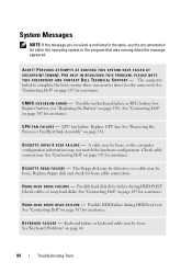
... be loose. Possible motherboard failure or RTC battery low. K E Y B O A R D F A I L U R E - Replace battery (see the documentation for assistance. Keyboard failure or keyboard cable may be defective or a cable may not match the hardware configuration. C M O S C H E C K S U M E R R O R - D I S K E T T E R E A D F A I L U R E - D I S K D R I V E F A I L U R E - See "Contacting Dell" on page 187 for assistance. Possible hard disk drive failure during HDD boot test. FOR HELP IN RESOLVING THIS...
... be loose. Possible motherboard failure or RTC battery low. K E Y B O A R D F A I L U R E - Replace battery (see the documentation for assistance. Keyboard failure or keyboard cable may be defective or a cable may not match the hardware configuration. C M O S C H E C K S U M E R R O R - D I S K E T T E R E A D F A I L U R E - D I S K D R I V E F A I L U R E - See "Contacting Dell" on page 187 for assistance. Possible hard disk drive failure during HDD boot test. FOR HELP IN RESOLVING THIS...
Owner's Manual
Page 85
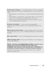
... YOU BACK UP YOUR DATA REGULARLY. Replace the floppy disk with one that the boot sequence information is your computer. N O B O O T D E V I C E A V A I S K E T T E - See "Entering System Setup" on page 187 for the USB device. See "Contacting Dell" on page 174. Disconnect the USB device. A PARAMETER OUT OF RANGE MAY OR MAY NOT INDICATE A POTENTIAL HARD DRIVE PROBLEM. -
... YOU BACK UP YOUR DATA REGULARLY. Replace the floppy disk with one that the boot sequence information is your computer. N O B O O T D E V I C E A V A I S K E T T E - See "Entering System Setup" on page 187 for the USB device. See "Contacting Dell" on page 174. Disconnect the USB device. A PARAMETER OUT OF RANGE MAY OR MAY NOT INDICATE A POTENTIAL HARD DRIVE PROBLEM. -

Owner's Manual
Page 128
...; 1 2 1 interface cable 2 interface connector Connecting and Disconnecting Drive Cables When connecting and disconnecting a serial ATA data cable, disconnect the cable using the pull-tab. The serial ATA interface connectors are replacing a hard drive that will sufficiently cushion it. Instead, set it is , a... notch or a missing pin on the other connector. Hard Drives CAUTION: Before you want to verify that it on a surface, such...
...; 1 2 1 interface cable 2 interface connector Connecting and Disconnecting Drive Cables When connecting and disconnecting a serial ATA data cable, disconnect the cable using the pull-tab. The serial ATA interface connectors are replacing a hard drive that will sufficiently cushion it. Instead, set it is , a... notch or a missing pin on the other connector. Hard Drives CAUTION: Before you want to verify that it on a surface, such...

Owner's Manual
Page 130
... "System Setup" on page 174), then go to the "Drives" section of the system setup and under Drive 0 through 3, set the Drive to the correct configuration. 8 Replace the computer cover (see "Replacing the Computer Cover" on page 166). 9 Connect computer and other devices to reflect these changes in the hard drive bay. 130 Removing and Installing Parts
... "System Setup" on page 174), then go to the "Drives" section of the system setup and under Drive 0 through 3, set the Drive to the correct configuration. 8 Replace the computer cover (see "Replacing the Computer Cover" on page 166). 9 Connect computer and other devices to reflect these changes in the hard drive bay. 130 Removing and Installing Parts

Owner's Manual
Page 131
... or device and then plug it into the computer. 1 5 2 6 3 4 1 hard drive 4 system board connector 2 power cable 5 screws (4) 3 serial ATA data cable 6 screw holes in the hard drive bay (4) 6 Replace and tighten the four screws to secure the hard drive. 7 Connect the power and data cables to the drive. 8 Connect the data cable to the system board. 9 Check all...
... or device and then plug it into the computer. 1 5 2 6 3 4 1 hard drive 4 system board connector 2 power cable 5 screws (4) 3 serial ATA data cable 6 screw holes in the hard drive bay (4) 6 Replace and tighten the four screws to secure the hard drive. 7 Connect the power and data cables to the drive. 8 Connect the data cable to the system board. 9 Check all...
Owner's Manual
Page 133
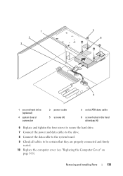
1 2 3 5 6 4 1 second hard drive (optional) 4 system board connector 2 power cable 5 screws (4) 3 serial ATA data cable 6 screw holes in the hard drive bay (4) 6 Replace and tighten the four screws to secure the hard drive. 7 Connect the power and data cables to the drive. 8 Connect the data cable to the system board. 9 Check all cables to be certain that they are properly connected and firmly seated. 10 Replace the computer cover (see "Replacing the Computer Cover" on page 166). Removing and Installing Parts 133
1 2 3 5 6 4 1 second hard drive (optional) 4 system board connector 2 power cable 5 screws (4) 3 serial ATA data cable 6 screw holes in the hard drive bay (4) 6 Replace and tighten the four screws to secure the hard drive. 7 Connect the power and data cables to the drive. 8 Connect the data cable to the system board. 9 Check all cables to be certain that they are properly connected and firmly seated. 10 Replace the computer cover (see "Replacing the Computer Cover" on page 166). Removing and Installing Parts 133
Owner's Manual
Page 152
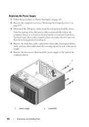
Replacing the Power Supply 1 Follow the procedures in the computer chassis as you remove them from being pinched or crimped. 4 Remove the hard drive cable, optical drive data cable, front panel ribbon cable, and any other cables from the securing clip on the side of the power supply. ... Computer Cover" on page 103). 3 Disconnect the DC power cables from the system board and drives. You must route these cables properly when you replace them to prevent them from the system board and the drives. Note the routing of the computer chassis. 1 2 1 power supply 2 screws (4) 152 Removing...
Replacing the Power Supply 1 Follow the procedures in the computer chassis as you remove them from being pinched or crimped. 4 Remove the hard drive cable, optical drive data cable, front panel ribbon cable, and any other cables from the securing clip on the side of the power supply. ... Computer Cover" on page 103). 3 Disconnect the DC power cables from the system board and drives. You must route these cables properly when you replace them to prevent them from the system board and the drives. Note the routing of the computer chassis. 1 2 1 power supply 2 screws (4) 152 Removing...
Owner's Manual
Page 153
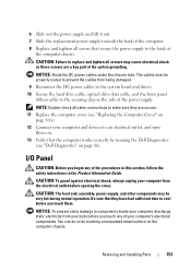
...CAUTION: The heat sink assembly, power supply, and other components may cause electrical shock as these screws are secure. 11 Replace the computer cover (see "Dell Diagnostics" on page 166). 12 Connect your computer, discharge static electricity from the electrical outlet before you touch any of the... the system board and drives. 10 Secure the hard drive cable, optical drive data cable, and the front panel ribbon cable to the back of the computer chassis. Removing and Installing Parts 153 6 Slide out the power supply and lift it out. 7 Slide the replacement power supply towards the...
...CAUTION: The heat sink assembly, power supply, and other components may cause electrical shock as these screws are secure. 11 Replace the computer cover (see "Dell Diagnostics" on page 166). 12 Connect your computer, discharge static electricity from the electrical outlet before you touch any of the... the system board and drives. 10 Secure the hard drive cable, optical drive data cable, and the front panel ribbon cable to the back of the computer chassis. Removing and Installing Parts 153 6 Slide out the power supply and lift it out. 7 Slide the replacement power supply towards the...
Owner's Manual
Page 208
... Guide, 11 regulatory, 11 safety, 11 Setup Diagram, 11 warranty, 11 drive-panel insert removing, 138 replacing, 139, 149 drivers, 89 about, 89 identifying, 90 reinstalling, 90 Drivers and Utilities media, 91 Dell Diagnostics, 86 drives, 126 hard drive, 128 installing floppy, 136 installing hard drive, 130 drives (continued) installing optical, 145, 147 problems, 60 removing floppy, 134 removing...
... Guide, 11 regulatory, 11 safety, 11 Setup Diagram, 11 warranty, 11 drive-panel insert removing, 138 replacing, 139, 149 drivers, 89 about, 89 identifying, 90 reinstalling, 90 Drivers and Utilities media, 91 Dell Diagnostics, 86 drives, 126 hard drive, 128 installing floppy, 136 installing hard drive, 130 drives (continued) installing optical, 145, 147 problems, 60 removing floppy, 134 removing...
Owner's Manual
Page 209
..., 136 removing, 134 H hard drive installing, 130 installing second, 132 problems, 62 removing, 129 hardware beep codes, 82 conflicts, 100 Dell Diagnostics, 86 Hardware Troubleshooter, 100 hibernate mode, 36, 38, 40 I I/O panel replacing, 155 installing parts before you begin, 101 recommended tools, 101 turning off your computer, 102 Internet problems, 62 Internet connection about...
..., 136 removing, 134 H hard drive installing, 130 installing second, 132 problems, 62 removing, 129 hardware beep codes, 82 conflicts, 100 Dell Diagnostics, 86 Hardware Troubleshooter, 100 hibernate mode, 36, 38, 40 I I/O panel replacing, 155 installing parts before you begin, 101 recommended tools, 101 turning off your computer, 102 Internet problems, 62 Internet connection about...


