Owner's Manual
Page 2
... damage to hardware or loss of data and tells you purchased a Dell™ n Series computer, any manner whatsoever without notice. © 2007 Dell Inc. Microsoft, Windows, Outlook, and Windows Vista are trademarks of Dell Inc. If you how to Microsoft® Windows® operating systems...or death. Model DCMF July 2007 P/N DX333 Rev. Dell Inc. A01 Trademarks used in this text: Dell, the DELL logo, Vostro, TravelLite, and Strike Zone are trademarks of your computer. and is a registered trademark owned by Dell under license; Blu-ray Disc and the Blu-ray Disc...
... damage to hardware or loss of data and tells you purchased a Dell™ n Series computer, any manner whatsoever without notice. © 2007 Dell Inc. Microsoft, Windows, Outlook, and Windows Vista are trademarks of Dell Inc. If you how to Microsoft® Windows® operating systems...or death. Model DCMF July 2007 P/N DX333 Rev. Dell Inc. A01 Trademarks used in this text: Dell, the DELL logo, Vostro, TravelLite, and Strike Zone are trademarks of your computer. and is a registered trademark owned by Dell under license; Blu-ray Disc and the Blu-ray Disc...
Owner's Manual
Page 3
Contents 1 Finding Information 11 2 Setting Up and Using Your Computer . . . 15 Front View of the Computer 15 Back View of the Computer 18 Back Panel Connectors 20 Installing Your Computer in an Enclosure 22 Setting Up a Printer 24 Printer Cable 24 Connecting a USB Printer 24 Playing CDs and DVDs 26 Adjusting the Volume 27 Adjusting the Picture 27 Copying CDs and DVDs 28 Using a Media Card Reader (Optional 31 Connecting Two Monitors 33 Connecting Two Monitors With VGA Connectors 33 Connecting One Monitor With a VGA Connector and One Monitor With a DVI Connector 34 Connecting ...
Contents 1 Finding Information 11 2 Setting Up and Using Your Computer . . . 15 Front View of the Computer 15 Back View of the Computer 18 Back Panel Connectors 20 Installing Your Computer in an Enclosure 22 Setting Up a Printer 24 Printer Cable 24 Connecting a USB Printer 24 Playing CDs and DVDs 26 Adjusting the Volume 27 Adjusting the Picture 27 Copying CDs and DVDs 28 Using a Media Card Reader (Optional 31 Connecting Two Monitors 33 Connecting Two Monitors With VGA Connectors 33 Connecting One Monitor With a VGA Connector and One Monitor With a DVI Connector 34 Connecting ...
Owner's Manual
Page 4
Power Management Options in Windows XP 35 Standby Mode 35 Hibernate Mode 36 Power Options Properties 37 Power Management Options in Windows Vista . . . . 38 Standby Mode 39 Hibernate Mode 40 Power Plan Properties 40 Enabling SpeedStep™ Technology 41 About RAID Configurations 42 RAID Level 1 Configuration 42 Configuring Your Hard Drives for RAID 43 Configuring for RAID Using the Intel® Option ROM Utility 44 Configuring for RAID Using the Intel® Matrix Storage Manager 45 Transferring Information to a New Computer 49 Setting Up a Home and Office Network 53 ...
Power Management Options in Windows XP 35 Standby Mode 35 Hibernate Mode 36 Power Options Properties 37 Power Management Options in Windows Vista . . . . 38 Standby Mode 39 Hibernate Mode 40 Power Plan Properties 40 Enabling SpeedStep™ Technology 41 About RAID Configurations 42 RAID Level 1 Configuration 42 Configuring Your Hard Drives for RAID 43 Configuring for RAID Using the Intel® Option ROM Utility 44 Configuring for RAID Using the Intel® Matrix Storage Manager 45 Transferring Information to a New Computer 49 Setting Up a Home and Office Network 53 ...

Owner's Manual
Page 5
Drive Problems 60 Optical drive problems 61 Hard drive problems 62 E-Mail, Modem, and Internet Problems 62 Error Messages 65 Keyboard Problems 66 Lockups and Software Problems 67 The computer does not start up 67 The computer stops responding 67 A program stops responding 67 A program crashes repeatedly 67 A program is designed for an earlier Microsoft® Windows® operating system 68 A solid blue screen appears 68 Other software problems 69 Media Card Reader Problems 70 Memory Problems 71 Mouse Problems 72 Network Problems 73 Power Problems 74 Printer Problems 75 ...
Drive Problems 60 Optical drive problems 61 Hard drive problems 62 E-Mail, Modem, and Internet Problems 62 Error Messages 65 Keyboard Problems 66 Lockups and Software Problems 67 The computer does not start up 67 The computer stops responding 67 A program stops responding 67 A program crashes repeatedly 67 A program is designed for an earlier Microsoft® Windows® operating system 68 A solid blue screen appears 68 Other software problems 69 Media Card Reader Problems 70 Memory Problems 71 Mouse Problems 72 Network Problems 73 Power Problems 74 Printer Problems 75 ...
Owner's Manual
Page 6
... Power Lights 81 Beep Codes 82 System Messages 84 Dell Diagnostics 86 When to Use the Dell Diagnostics 86 Starting the Dell Diagnostics From Your Hard Drive 86 Starting the Dell Diagnostics From the Drivers and Utilities Media 87 Dell Diagnostics Main Menu 87 Drivers 89 What Is a ...Driver 89 Identifying Drivers 90 Reinstalling Drivers and Utilities 90 Restoring Your Operating System 93 Using Microsoft Windows System Restore . . . . . 94 Using Dell PC Restore and Dell Factory Image Restore 95 Using...
... Power Lights 81 Beep Codes 82 System Messages 84 Dell Diagnostics 86 When to Use the Dell Diagnostics 86 Starting the Dell Diagnostics From Your Hard Drive 86 Starting the Dell Diagnostics From the Drivers and Utilities Media 87 Dell Diagnostics Main Menu 87 Drivers 89 What Is a ...Driver 89 Identifying Drivers 90 Reinstalling Drivers and Utilities 90 Restoring Your Operating System 93 Using Microsoft Windows System Restore . . . . . 94 Using Dell PC Restore and Dell Factory Image Restore 95 Using...
Owner's Manual
Page 7
5 Removing and Installing Parts 101 Before You Begin 101 Recommended Tools 101 Turning Off Your Computer 102 Before Working Inside Your Computer 102 Removing the Computer Cover 103 Inside View of Your Computer 105 System Board Components 106 Power Supply DC Connector Pin Assignments . . . . . 108 Memory 111 Memory Installation Guidelines 112 Installing Memory 113 Removing Memory 115 Cards 115 PCI and PCI Express Cards 116 Bezel 123 Removing the Bezel 123 Replacing the Bezel 125 Drives 126 Recommended Drive Cable Connections . . . . . 127 Connecting Drive Cables 127 Drive ...
5 Removing and Installing Parts 101 Before You Begin 101 Recommended Tools 101 Turning Off Your Computer 102 Before Working Inside Your Computer 102 Removing the Computer Cover 103 Inside View of Your Computer 105 System Board Components 106 Power Supply DC Connector Pin Assignments . . . . . 108 Memory 111 Memory Installation Guidelines 112 Installing Memory 113 Removing Memory 115 Cards 115 PCI and PCI Express Cards 116 Bezel 123 Removing the Bezel 123 Replacing the Bezel 125 Drives 126 Recommended Drive Cable Connections . . . . . 127 Connecting Drive Cables 127 Drive ...
Owner's Manual
Page 8
Battery 150 Replacing the Battery 150 Power Supply 151 Replacing the Power Supply 152 I/O Panel 153 Removing the I/O Panel 154 Installing the I/O Panel 155 Processor Fan 155 Removing the Processor Fan/Heat Sink Assembly 156 Installing the Processor Fan/Heat Sink Assembly 157 Processor 158 Removing the Processor 158 Installing the Processor 159 Chassis Fan 162 Removing the Chassis Fan 162 Replacing the Chassis Fan 163 System Board 164 Removing the System Board 164 Installing the System Board 165 Replacing the Computer Cover 166 6 Appendix 169 Specifications 169 System ...
Battery 150 Replacing the Battery 150 Power Supply 151 Replacing the Power Supply 152 I/O Panel 153 Removing the I/O Panel 154 Installing the I/O Panel 155 Processor Fan 155 Removing the Processor Fan/Heat Sink Assembly 156 Installing the Processor Fan/Heat Sink Assembly 157 Processor 158 Removing the Processor 158 Installing the Processor 159 Chassis Fan 162 Removing the Chassis Fan 162 Replacing the Chassis Fan 163 System Board 164 Removing the System Board 164 Installing the System Board 165 Replacing the Computer Cover 166 6 Appendix 169 Specifications 169 System ...
Owner's Manual
Page 9
System Setup Options 176 Boot Sequence 178 Clearing Forgotten Passwords 180 Clearing CMOS Settings 181 Flashing the BIOS 182 Cleaning Your Computer 182 Computer, Keyboard, and Monitor 183 Mouse 183 Floppy Drive 183 CDs and DVDs 184 Dell Technical Support Policy (U.S. Only 184 Definition of "Dell-Installed" Software and Peripherals 185 Definition of "Third-Party" Software and Peripherals 185 FCC Notice (U.S. Only 185 FCC Class B 185 Contacting Dell 187 Glossary 189 Index 207 Contents 9
System Setup Options 176 Boot Sequence 178 Clearing Forgotten Passwords 180 Clearing CMOS Settings 181 Flashing the BIOS 182 Cleaning Your Computer 182 Computer, Keyboard, and Monitor 183 Mouse 183 Floppy Drive 183 CDs and DVDs 184 Dell Technical Support Policy (U.S. Only 184 Definition of "Dell-Installed" Software and Peripherals 185 Definition of "Third-Party" Software and Peripherals 185 FCC Notice (U.S. Only 185 FCC Class B 185 Contacting Dell 187 Glossary 189 Index 207 Contents 9

Owner's Manual
Page 11
NOTE: Additional information may ship with your system. only) • Safety instructions • Regulatory information • Ergonomics information • End User License Agreement Dell™ Product Information Guide • How to set up my computer Setup Diagram See the setup diagram that came with your computer. Finding Information 11 ...
NOTE: Additional information may ship with your system. only) • Safety instructions • Regulatory information • Ergonomics information • End User License Agreement Dell™ Product Information Guide • How to set up my computer Setup Diagram See the setup diagram that came with your computer. Finding Information 11 ...

Owner's Manual
Page 12
... Microsoft® Windows® License These labels are located on your computer. • Use the Service Tag to identify your computer when you use support.dell.com or contact support. • Enter the Express Service Code to discourage removal of the label. 12 Finding Information
... Microsoft® Windows® License These labels are located on your computer. • Use the Service Tag to identify your computer when you use support.dell.com or contact support. • Enter the Express Service Code to discourage removal of the label. 12 Finding Information
Owner's Manual
Page 13
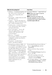
... support for your computer, you should also reinstall the DSS utility. The software automatically detects your computer, and click Submit. support.dell.com tips, articles from technicians, and online courses, frequently asked questions • Community - Certified drivers, patches, and software updates... Device, scroll to System configuration. What Are You Looking For? NOTE: Corporate, government, and education customers can also use the customized Dell Premier Support website • Upgrades - components, such as memory, the hard drive, and the operating system • Customer Care -...
... support for your computer, you should also reinstall the DSS utility. The software automatically detects your computer, and click Submit. support.dell.com tips, articles from technicians, and online courses, frequently asked questions • Community - Certified drivers, patches, and software updates... Device, scroll to System configuration. What Are You Looking For? NOTE: Corporate, government, and education customers can also use the customized Dell Premier Support website • Upgrades - components, such as memory, the hard drive, and the operating system • Customer Care -...

Owner's Manual
Page 14
What Are You Looking For? • How to use Windows Vista™ • How to work with programs and files • How to personalize my desktop Find it Here Windows Help and Support Center 1 To access Windows Help and Support: • In Windows XP, click Start and click Help and Support. • In Windows Vista™, click the Windows Vista Start button and click Help and Support. 2 Type a word or phrase that describes your problem, and then click the arrow icon. 3 Click the topic that describes your problem. 4 Follow the instructions on the screen. 14 Finding Information
What Are You Looking For? • How to use Windows Vista™ • How to work with programs and files • How to personalize my desktop Find it Here Windows Help and Support Center 1 To access Windows Help and Support: • In Windows XP, click Start and click Help and Support. • In Windows Vista™, click the Windows Vista Start button and click Help and Support. 2 Type a word or phrase that describes your problem, and then click the arrow icon. 3 Click the topic that describes your problem. 4 Follow the instructions on the screen. 14 Finding Information
Owner's Manual
Page 15
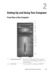
Setting Up and Using Your Computer Front View of the Computer 1 2 3 4 5 6 7 8 9 10 11 12 13 14 1 location of Service Tag Use the Service Tag to identify your computer when you access the Dell Support website or call technical support. 2 optical drive Use the optical drive for playing a CD/DVD. Setting Up and Using Your Computer 15
Setting Up and Using Your Computer Front View of the Computer 1 2 3 4 5 6 7 8 9 10 11 12 13 14 1 location of Service Tag Use the Service Tag to identify your computer when you access the Dell Support website or call technical support. 2 optical drive Use the optical drive for playing a CD/DVD. Setting Up and Using Your Computer 15
Owner's Manual
Page 16
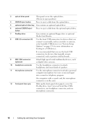
button 7 FlexBay drive Can contain an optional floppy drive or optional Media Card Reader. 8 USB 2.0 connectors (4) Use the front USB connectors for devices that typically remain connected, such as printers and keyboards. 9 IEEE 1394 connector (optional) Attach high-speed serial multimedia devices, such as joysticks or cameras, or for bootable USB devices (see "System Setup Options" on page 176 for more information on the card. 12 front panel door grip Slide up the front panel door grip to eject a disk from the optical drive. 5 optional optical drive bay Can contain an optional ...
button 7 FlexBay drive Can contain an optional floppy drive or optional Media Card Reader. 8 USB 2.0 connectors (4) Use the front USB connectors for devices that typically remain connected, such as printers and keyboards. 9 IEEE 1394 connector (optional) Attach high-speed serial multimedia devices, such as joysticks or cameras, or for bootable USB devices (see "System Setup Options" on page 176 for more information on the card. 12 front panel door grip Slide up the front panel door grip to eject a disk from the optical drive. 5 optional optical drive bay Can contain an optional ...
Owner's Manual
Page 17
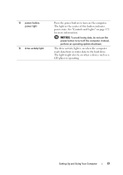
The drive activity light is operating. NOTICE: To avoid losing data, do not use the power button to the hard drive. 13 power button, power light 14 drive activity light Press the power button to turn off the computer. The light might also be on the computer. See "Controls and Lights" on when the computer reads data from or writes data to turn on when a device such as a CD player is on page 172 for more information. Instead, perform an operating system shutdown. The light in the center of this button indicates power state. Setting Up and Using Your Computer 17
The drive activity light is operating. NOTICE: To avoid losing data, do not use the power button to the hard drive. 13 power button, power light 14 drive activity light Press the power button to turn off the computer. The light might also be on the computer. See "Controls and Lights" on when the computer reads data from or writes data to turn on when a device such as a CD player is on page 172 for more information. Instead, perform an operating system shutdown. The light in the center of this button indicates power state. Setting Up and Using Your Computer 17
Owner's Manual
Page 18
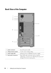
Plug USB, audio, and other devices into the appropriate connector. See "Back Panel Connectors" on page 20 for power supply. Back View of the Computer 1 2 3 7 4 6 5 1 power connector 2 voltage selector switch 3 power supply LED 4 back panel connectors Insert the power cable. Indicates power availability for more information. 18 Setting Up and Using Your Computer Used to select voltage rating.
Plug USB, audio, and other devices into the appropriate connector. See "Back Panel Connectors" on page 20 for power supply. Back View of the Computer 1 2 3 7 4 6 5 1 power connector 2 voltage selector switch 3 power supply LED 4 back panel connectors Insert the power cable. Indicates power availability for more information. 18 Setting Up and Using Your Computer Used to select voltage rating.
Owner's Manual
Page 19
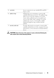
To use the padlock rings, insert a commercially available padlock through the rings, and then lock the padlock. Padlock rings are blocked. Security cable slot lets you to secure the computer cover to the chassis with the device. For more information, see the instructions included with a padlock to prevent unauthorized access to the computer. Blocking the vents would cause serious thermal problems. Setting Up and Using Your Computer 19 The padlock rings allow you attach a commercially available antitheft device to the inside of the system air vents are for any installed PCI and ...
To use the padlock rings, insert a commercially available padlock through the rings, and then lock the padlock. Padlock rings are blocked. Security cable slot lets you to secure the computer cover to the chassis with the device. For more information, see the instructions included with a padlock to prevent unauthorized access to the computer. Blocking the vents would cause serious thermal problems. Setting Up and Using Your Computer 19 The padlock rings allow you attach a commercially available antitheft device to the inside of the system air vents are for any installed PCI and ...
Owner's Manual
Page 20
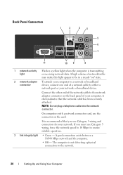
It is not detecting a physical connection to either a network port or your computer. If you use Category 5 wiring and connectors for your network. NOTE: Do not plug a telephone cable into the network connector. A good connection exists between a 10/100 Mbps network and the computer. • Off - A high volume of network traffic may make this light appear to be in a steady "on" state. 2 network adapter To attach your computer to a network or broadband connector device, connect one end of a network cable to the network. 20 Setting Up and Using Your Computer A click ...
It is not detecting a physical connection to either a network port or your computer. If you use Category 5 wiring and connectors for your network. NOTE: Do not plug a telephone cable into the network connector. A good connection exists between a 10/100 Mbps network and the computer. • Off - A high volume of network traffic may make this light appear to be in a steady "on" state. 2 network adapter To attach your computer to a network or broadband connector device, connect one end of a network cable to the network. 20 Setting Up and Using Your Computer A click ...
Owner's Manual
Page 21
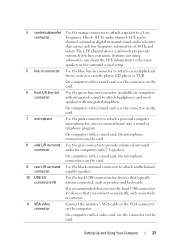
On computers with a sound card, use the connector on the card. 6 front L/R line-out Use the green line-out connector (available on computers connector with integrated sound) to provide enhanced surround connector audio for devices that carries only low frequency information of 80 Hz and below. connector capable speakers. 10 USB 2.0 connectors (4) Use the back USB connectors for devices that typically remain connected, such as a cassette player, CD player, or VCR. On computers with integrated amplifiers. The LFE channel drives a subwoofer to a Low connector Frequency ...
On computers with a sound card, use the connector on the card. 6 front L/R line-out Use the green line-out connector (available on computers connector with integrated sound) to provide enhanced surround connector audio for devices that carries only low frequency information of 80 Hz and below. connector capable speakers. 10 USB 2.0 connectors (4) Use the back USB connectors for devices that typically remain connected, such as a cassette player, CD player, or VCR. On computers with integrated amplifiers. The LFE channel drives a subwoofer to a Low connector Frequency ...
Owner's Manual
Page 22
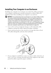
The room ambient temperature needs to be of a type that allows at least 30% airflow through the enclosure (front and back). • If your computer is at 25° C (77° F), depending on a desk or under a desk, leave at least 5.1 cm (2 in.) clearance from the back of the computer to be a consideration when installing your computer in an enclosure. For example, if the ambient room temperature is installed in .) minimum clearance on all vented sides of the computer to the wall to permit the airflow required for proper ventilation. • If your enclosure has doors, they need to...
The room ambient temperature needs to be of a type that allows at least 30% airflow through the enclosure (front and back). • If your computer is at 25° C (77° F), depending on a desk or under a desk, leave at least 5.1 cm (2 in.) clearance from the back of the computer to be a consideration when installing your computer in an enclosure. For example, if the ambient room temperature is installed in .) minimum clearance on all vented sides of the computer to the wall to permit the airflow required for proper ventilation. • If your enclosure has doors, they need to...
