Owner's Manual
Page 3
... Back View of the Computer 18 Back Panel Connectors 20 Installing Your Computer in an Enclosure 22 Setting Up a Printer 24 Printer Cable 24 Connecting a USB Printer 24 Playing CDs and DVDs 26 Adjusting the Volume 27 Adjusting the Picture 27 Copying CDs and DVDs 28 Using a Media Card Reader (Optional...
... Back View of the Computer 18 Back Panel Connectors 20 Installing Your Computer in an Enclosure 22 Setting Up a Printer 24 Printer Cable 24 Connecting a USB Printer 24 Playing CDs and DVDs 26 Adjusting the Volume 27 Adjusting the Picture 27 Copying CDs and DVDs 28 Using a Media Card Reader (Optional...
Owner's Manual
Page 13
... and support for your 5 Under Select a Device, scroll to view the appropriate support site. Finding Information 13 Troubleshooting hints and Dell Support Website - DSS provides critical updates for Dell™ 3.5-inch USB floppy drives, optical drives, and USB devices. If To download Desktop System Software: you reinstall the operating system for at premier.support...
... and support for your 5 Under Select a Device, scroll to view the appropriate support site. Finding Information 13 Troubleshooting hints and Dell Support Website - DSS provides critical updates for Dell™ 3.5-inch USB floppy drives, optical drives, and USB devices. If To download Desktop System Software: you reinstall the operating system for at premier.support...
Owner's Manual
Page 16
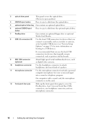
... connected, such as printers and keyboards. 9 IEEE 1394 connector (optional) Attach high-speed serial multimedia devices, such as joysticks or cameras, or for bootable USB devices (see "System Setup Options" on the card. 12 front panel door grip Slide up the front panel door grip to cover the FlexBay drive..., four Universal Serial Bus (USB) connectors, one headphone connector, and one microphone connector. 16 Setting Up and Using Your Computer It is on page 176 for voice or musical ...
... connected, such as printers and keyboards. 9 IEEE 1394 connector (optional) Attach high-speed serial multimedia devices, such as joysticks or cameras, or for bootable USB devices (see "System Setup Options" on the card. 12 front panel door grip Slide up the front panel door grip to cover the FlexBay drive..., four Universal Serial Bus (USB) connectors, one headphone connector, and one microphone connector. 16 Setting Up and Using Your Computer It is on page 176 for voice or musical ...
Owner's Manual
Page 18
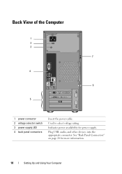
Indicates power availability for more information. 18 Setting Up and Using Your Computer Back View of the Computer 1 2 3 7 4 6 5 1 power connector 2 voltage selector switch 3 power supply LED 4 back panel connectors Insert the power cable. Plug USB, audio, and other devices into the appropriate connector. See "Back Panel Connectors" on page 20 for power supply. Used to select voltage rating.
Indicates power availability for more information. 18 Setting Up and Using Your Computer Back View of the Computer 1 2 3 7 4 6 5 1 power connector 2 voltage selector switch 3 power supply LED 4 back panel connectors Insert the power cable. Plug USB, audio, and other devices into the appropriate connector. See "Back Panel Connectors" on page 20 for power supply. Used to select voltage rating.
Owner's Manual
Page 21
... 9 rear L/R surround Use the black surround connector to provide enhanced surround connector audio for computers with a video card, use the front USB connectors for devices that typically remain connected, such as a cassette player, CD player, or VCR. On computers with a sound card, ... headphones and most speakers with a sound card, the microphone connector is on the computer. connector capable speakers. 10 USB 2.0 connectors (4) Use the back USB connectors for devices that carries only low frequency information of 80 Hz and below. On computers with integrated amplifiers. The...
... 9 rear L/R surround Use the black surround connector to provide enhanced surround connector audio for computers with a video card, use the front USB connectors for devices that typically remain connected, such as a cassette player, CD player, or VCR. On computers with a sound card, ... headphones and most speakers with a sound card, the microphone connector is on the computer. connector capable speakers. 10 USB 2.0 connectors (4) Use the back USB connectors for devices that carries only low frequency information of 80 Hz and below. On computers with integrated amplifiers. The...
Owner's Manual
Page 24
... contact the printer manufacturer. If you purchased a printer cable at the same time you have not already done so. 2 Attach the USB printer cable to the USB connectors on the computer and the printer. Printer Cable Your printer connects to the computer. • Load paper and install the toner or... ink cartridge. The USB connectors fit only one way. 24 Setting Up and Using Your Computer See the documentation that came with the printer for setup information, including ...
... contact the printer manufacturer. If you purchased a printer cable at the same time you have not already done so. 2 Attach the USB printer cable to the USB connectors on the computer and the printer. Printer Cable Your printer connects to the computer. • Load paper and install the toner or... ink cartridge. The USB connectors fit only one way. 24 Setting Up and Using Your Computer See the documentation that came with the printer for setup information, including ...
Owner's Manual
Page 25
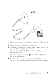
Setting Up and Using Your Computer 25 1 2 3 1 USB connector on computer 2 USB connector on printer 3 USB printer cable 3 Turn on the printer and then turn on the computer. 4 Depending on page 90 and the documentation that came with your computer's operating ...
Setting Up and Using Your Computer 25 1 2 3 1 USB connector on computer 2 USB connector on printer 3 USB printer cable 3 Turn on the printer and then turn on the computer. 4 Depending on page 90 and the documentation that came with your computer's operating ...

Owner's Manual
Page 66
... computer. ENSURE THAT THE USB PORTS ARE ENABLED IN THE SYSTEM SETUP P R O G R A M - TE S T T H E K E Y B O A R D - O P E R A T I N G S YS T E M N O T F O U N D - Straighten bent pins. • Remove keyboard extension cables and connect the keyboard directly to the computer, and try using the keyboard. Contact Dell (see "Turning Off Your...8226; Ensure that the keyboard cable is firmly connected to the computer. • Shut down the computer (see "Contacting Dell" on the setup diagram for your computer, and then restart the computer. • Check the cable connector for bent ...
... computer. ENSURE THAT THE USB PORTS ARE ENABLED IN THE SYSTEM SETUP P R O G R A M - TE S T T H E K E Y B O A R D - O P E R A T I N G S YS T E M N O T F O U N D - Straighten bent pins. • Remove keyboard extension cables and connect the keyboard directly to the computer, and try using the keyboard. Contact Dell (see "Turning Off Your...8226; Ensure that the keyboard cable is firmly connected to the computer. • Shut down the computer (see "Contacting Dell" on the setup diagram for your computer, and then restart the computer. • Check the cable connector for bent ...
Owner's Manual
Page 72
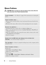
... press . 3 After the computer turns off, reconnect the mouse cable as shown on the setup diagram for your computer. 4 Start the computer. ENSURE THAT THE USB PORTS ARE ENABLED IN THE SYSTEM SETUP P R O G R A M - Mouse Problems CAUTION: Before you begin any of the procedures in this section, follow the safety instructions in...
... press . 3 After the computer turns off, reconnect the mouse cable as shown on the setup diagram for your computer. 4 Start the computer. ENSURE THAT THE USB PORTS ARE ENABLED IN THE SYSTEM SETUP P R O G R A M - Mouse Problems CAUTION: Before you begin any of the procedures in this section, follow the safety instructions in...
Owner's Manual
Page 76
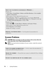
... printers or fax printers. 2 If the printer is listed, right-click the printer icon. 3 Click Properties and click Ports. 4 Adjust the settings, as needed. For a USB printer, ensure that the Print to the following port(s): setting is unlocked if it has a locking tab or button. U N L O C K T H E S C A N N E R - VERIFY THAT THE PRINTER IS RECOGNIZED...: Before you need technical assistance for your scanner is LPT1 (Printer Port). For a parallel printer, ensure that the Print to the following port(s): setting is USB.
... printers or fax printers. 2 If the printer is listed, right-click the printer icon. 3 Click Properties and click Ports. 4 Adjust the settings, as needed. For a USB printer, ensure that the Print to the following port(s): setting is unlocked if it has a locking tab or button. U N L O C K T H E S C A N N E R - VERIFY THAT THE PRINTER IS RECOGNIZED...: Before you need technical assistance for your scanner is LPT1 (Printer Port). For a parallel printer, ensure that the Print to the following port(s): setting is USB.
Owner's Manual
Page 85
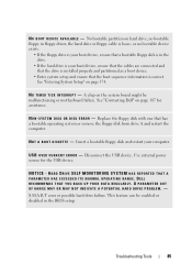
... might be enabled or disabled in the drive. • If the hard drive is your computer. See "Contacting Dell" on hard drive, no bootable floppy in floppy driver, the hard drive or floppy cable is loose, or no... possible hard drive failure. N O T I M E R T I C K I L A B L E - N O B O O T D E V I C E A V A I N T E R R U P T - No bootable partition on page 187 for the USB device. N O N - Replace the floppy disk with one that the boot sequence information is correct. U S B O V E R C U R R E N T E R R O R - HARD DRIVE SELF MONITORING SYSTEM HAS REPORTED THAT A PARAMETER HAS EXCEEDED...
... might be enabled or disabled in the drive. • If the hard drive is your computer. See "Contacting Dell" on hard drive, no bootable floppy in floppy driver, the hard drive or floppy cable is loose, or no... possible hard drive failure. N O T I M E R T I C K I L A B L E - N O B O O T D E V I C E A V A I N T E R R U P T - No bootable partition on page 187 for the USB device. N O N - Replace the floppy disk with one that the boot sequence information is correct. U S B O V E R C U R R E N T E R R O R - HARD DRIVE SELF MONITORING SYSTEM HAS REPORTED THAT A PARAMETER HAS EXCEEDED...
Owner's Manual
Page 141
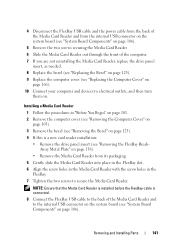
...• Remove the drive panel insert (see "Removing the FlexBay BreakAway Metal Plate" on page 138). • Remove the Media Card Reader from the internal USB connector on the system board (see "System Board Components" on page 106). 5 Remove the two screws securing the Media Card Reader. 6 Slide the Media ... Cover" on page 166). 10 Connect your computer and devices to electrical outlets, and then turn them on page 106). 4 Disconnect the FlexBay USB cable and the power cable from the back of the Media Card Reader and from its packaging. 5 Gently slide the Media Card Reader into place...
...• Remove the drive panel insert (see "Removing the FlexBay BreakAway Metal Plate" on page 138). • Remove the Media Card Reader from the internal USB connector on the system board (see "System Board Components" on page 106). 5 Remove the two screws securing the Media Card Reader. 6 Slide the Media ... Cover" on page 166). 10 Connect your computer and devices to electrical outlets, and then turn them on page 106). 4 Disconnect the FlexBay USB cable and the power cable from the back of the Media Card Reader and from its packaging. 5 Gently slide the Media Card Reader into place...
Owner's Manual
Page 170
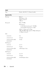
... connector size connector data width (maximum) PCI Express connector connector size connector data width (maximum) Realtec ALC888 (7.1 Channel audio) PCI 2.3 PCI Express 1.0A SATA 1.0 and 2.0 USB 2.0 PCI: 133 MB/s PCI Express: x1 slot bidirectional speed - 500 MB/s x16 slot bidirectional speed - 8GB/s SATA: 1.5 Gbps and 3.0 Gbps... USB: 480 Mbps high speed, 12 Mbps full speed, 1.2 Mbps low speed two 124 pins 32 bits one x1 36 pins 1 PCI Express lane one x16 ...
... connector size connector data width (maximum) PCI Express connector connector size connector data width (maximum) Realtec ALC888 (7.1 Channel audio) PCI 2.3 PCI Express 1.0A SATA 1.0 and 2.0 USB 2.0 PCI: 133 MB/s PCI Express: x1 slot bidirectional speed - 500 MB/s x16 slot bidirectional speed - 8GB/s SATA: 1.5 Gbps and 3.0 Gbps... USB: 480 Mbps high speed, 12 Mbps full speed, 1.2 Mbps low speed two 124 pins 32 bits one x1 36 pins 1 PCI Express lane one x16 ...
Owner's Manual
Page 171
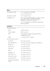
... Floppy drive Processor fan Chassis fan PCI 2.3 PCI Express x1 PCI Express x16 Front panel control Front panel USB Front panel audio HDA header one 3.5-inch drive bay (FlexBay) two 5.25-inch drive bays two 3.5-inch drive bays two 3.5-inch Serial ATA hard drives ...) or Media Card Reader (optional) 15-hole connector RJ-45 connector four front-panel and four back-panel USB 2.0compliant connectors six connectors for 7.1 support four 7-pin connectors two 10-pin connector (supports four USB ports) one 34-pin connector one 4-pin connector one 3-pin connector two 124-pin connectors one 36...
... Floppy drive Processor fan Chassis fan PCI 2.3 PCI Express x1 PCI Express x16 Front panel control Front panel USB Front panel audio HDA header one 3.5-inch drive bay (FlexBay) two 5.25-inch drive bays two 3.5-inch drive bays two 3.5-inch Serial ATA hard drives ...) or Media Card Reader (optional) 15-hole connector RJ-45 connector four front-panel and four back-panel USB 2.0compliant connectors six connectors for 7.1 support four 7-pin connectors two 10-pin connector (supports four USB ports) one 34-pin connector one 4-pin connector one 3-pin connector two 124-pin connectors one 36...
Owner's Manual
Page 177
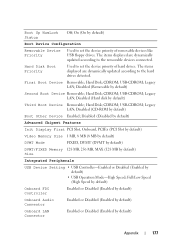
...; Disabled (Removable by default) Boot Other Device Enabled; Hard Disk; CDROM; Hard Disk; On (On by default) Appendix 177 CDROM; USB-CDROM; Disabled (CD-ROM by default) Second Boot Device Removable; Disabled (Disabled by default) Advanced Chipset Features Init Display First PCI Slot,..., DVMT (DVMT by default) DVMT/FIXED Memory 128 MB, 256 MB, MAX (128 MB by default) Size Integrated Peripherals USB Device Setting • USB Controller-Enabled or Disabled (Enabled by default) Third Boot Device Removable; Legacy LAN; Hard Disk; CDROM; The items displayed are...
...; Disabled (Removable by default) Boot Other Device Enabled; Hard Disk; CDROM; Hard Disk; On (On by default) Appendix 177 CDROM; USB-CDROM; Disabled (CD-ROM by default) Second Boot Device Removable; Disabled (Disabled by default) Advanced Chipset Features Init Display First PCI Slot,..., DVMT (DVMT by default) DVMT/FIXED Memory 128 MB, 256 MB, MAX (128 MB by default) Size Integrated Peripherals USB Device Setting • USB Controller-Enabled or Disabled (Enabled by default) Third Boot Device Removable; Legacy LAN; Hard Disk; CDROM; The items displayed are...
Owner's Manual
Page 178
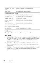
... no operating system, the computer generates an error message. 178 Appendix The computer attempts to change the boot sequence for devices. Disabled (Disabled by default) USB KB Wake-Up From S3 Enabled; If no CD is on the drive, the computer generates an error message. • CD Drive - Off (On by...
... no operating system, the computer generates an error message. 178 Appendix The computer attempts to change the boot sequence for devices. Disabled (Disabled by default) USB KB Wake-Up From S3 Enabled; If no CD is on the drive, the computer generates an error message. • CD Drive - Off (On by...
Owner's Manual
Page 179
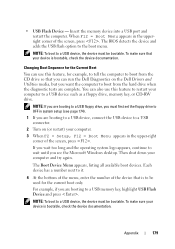
...screen, press . For example, if you are booting to a USB device, connect the USB device to a USB connector. 2 Turn on the Dell Drivers and Utilities media, but you want the computer to the boot menu. NOTE: To boot to a USB memory key, highlight USB Flash Device and press . Changing Boot Sequence for the Current ...in the upper-right corner of the screen, press . To make sure your computer and try again. You can run the Dell Diagnostics on (or restart) your device is to a USB device such as a floppy drive, memory key, or CD-RW drive. NOTE: If you can also use this feature ...
...screen, press . For example, if you are booting to a USB device, connect the USB device to a USB connector. 2 Turn on the Dell Drivers and Utilities media, but you want the computer to the boot menu. NOTE: To boot to a USB memory key, highlight USB Flash Device and press . Changing Boot Sequence for the Current ...in the upper-right corner of the screen, press . To make sure your computer and try again. You can run the Dell Diagnostics on (or restart) your device is to a USB device such as a floppy drive, memory key, or CD-RW drive. NOTE: If you can also use this feature ...
Owner's Manual
Page 193
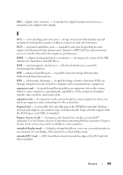
.... A circuit board that allows you insert an expansion card, connecting it passes in some computers, expanding the capabilities of your Dell™ computer. Examples include video, modem, and sound cards. A removable I/O card adhering to transfer data and often improves ... installs in computer and communications equipment. DVI - A type of data as dual display mode. ESD - ExpressCards support both the PCI Express and USB 2.0 standard. A rapid discharge of ExpressCards. Modems and network adapters are common types of static electricity. E ECC - ECP - EMI - A...
.... A circuit board that allows you insert an expansion card, connecting it passes in some computers, expanding the capabilities of your Dell™ computer. Examples include video, modem, and sound cards. A removable I/O card adhering to transfer data and often improves ... installs in computer and communications equipment. DVI - A type of data as dual display mode. ESD - ExpressCards support both the PCI Express and USB 2.0 standard. A rapid discharge of ExpressCards. Modems and network adapters are common types of static electricity. E ECC - ECP - EMI - A...
Owner's Manual
Page 203
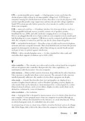
..., or e-mail attachments. A video standard for a few minutes to enable you or to 1600 x 1200. A common type of characters. USB devices can also be defined as x columns by z colors. V video controller - Memory that consists of colors that describes how text and graphics... and some computer networks. A UPS keeps a computer running for your computer. universal serial bus - virus - A program that can display. USB - Pairs of wires to protect against interference. UXGA - Graphics-based software, such as Windows operating systems, displays in video modes that is...
..., or e-mail attachments. A video standard for a few minutes to enable you or to 1600 x 1200. A common type of characters. USB devices can also be defined as x columns by z colors. V video controller - Memory that consists of colors that describes how text and graphics... and some computer networks. A UPS keeps a computer running for your computer. universal serial bus - virus - A program that can display. USB - Pairs of wires to protect against interference. UXGA - Graphics-based software, such as Windows operating systems, displays in video modes that is...
Owner's Manual
Page 207
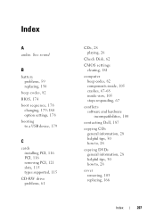
See sound B battery problems, 59 replacing, 150 beep codes, 82 BIOS, 174 boot sequence, 178 changing, 179-180 option settings, 178 booting to a USB device, 179 C cards installing PCI, 116 PCI, 116 removing PCI, 121 slots, 115 types supported, 115 CD-RW drive problems, 61 CDs, 28 ..., 181 computer beep codes, 82 components inside, 105 crashes, 67-68 inside view, 105 stops responding, 67 conflicts software and hardware incompatibilities, 100 contacting Dell, 187 copying CDs general information, 28 helpful tips, 30 how to, 28 copying DVDs general information, 28 helpful tips, 30 how to, 28 cover...
See sound B battery problems, 59 replacing, 150 beep codes, 82 BIOS, 174 boot sequence, 178 changing, 179-180 option settings, 178 booting to a USB device, 179 C cards installing PCI, 116 PCI, 116 removing PCI, 121 slots, 115 types supported, 115 CD-RW drive problems, 61 CDs, 28 ..., 181 computer beep codes, 82 components inside, 105 crashes, 67-68 inside view, 105 stops responding, 67 conflicts software and hardware incompatibilities, 100 contacting Dell, 187 copying CDs general information, 28 helpful tips, 30 how to, 28 copying DVDs general information, 28 helpful tips, 30 how to, 28 cover...


