Owner's Manual
Page 7
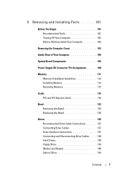
...Removing and Installing Parts 101 Before You Begin 101 Recommended Tools 101 Turning Off Your Computer 102 Before Working Inside Your Computer 102 Removing the Computer Cover 103 Inside View of Your Computer 105 System Board Components 106 Power Supply DC Connector Pin Assignments . . . . . 108 Memory 111 Memory Installation Guidelines 112 Installing Memory 113 Removing... Memory 115 Cards 115 PCI and PCI Express Cards 116 Bezel 123 Removing the Bezel 123 Replacing the Bezel 125 Drives ...
...Removing and Installing Parts 101 Before You Begin 101 Recommended Tools 101 Turning Off Your Computer 102 Before Working Inside Your Computer 102 Removing the Computer Cover 103 Inside View of Your Computer 105 System Board Components 106 Power Supply DC Connector Pin Assignments . . . . . 108 Memory 111 Memory Installation Guidelines 112 Installing Memory 113 Removing... Memory 115 Cards 115 PCI and PCI Express Cards 116 Bezel 123 Removing the Bezel 123 Replacing the Bezel 125 Drives ...

Owner's Manual
Page 59
Battery Problems CAUTION: There is a danger of a new battery exploding if it is correctly installed. • If a peripheral device does not work properly, contact Dell (see the program's documentation. R E P L A C E T H E B A T T E R Y - Replace the battery only with the same or equivalent type... the parts described in this section, follow the safety instructions in a program, see "Contacting Dell" on page 150). Troubleshooting Tips Follow these tips when you troubleshoot your computer: • If you added or removed a part before the problem started, review the installation procedures ...
Battery Problems CAUTION: There is a danger of a new battery exploding if it is correctly installed. • If a peripheral device does not work properly, contact Dell (see the program's documentation. R E P L A C E T H E B A T T E R Y - Replace the battery only with the same or equivalent type... the parts described in this section, follow the safety instructions in a program, see "Contacting Dell" on page 150). Troubleshooting Tips Follow these tips when you troubleshoot your computer: • If you added or removed a part before the problem started, review the installation procedures ...

Owner's Manual
Page 101
... on page 102. • You have performed the steps in "Turning Off Your Computer" on page 102 and "Before Working Inside Your Computer" on the Dell Support website at support.dell.com Removing and Installing Parts 101 Recommended Tools The procedures in your computer.
... on page 102. • You have performed the steps in "Turning Off Your Computer" on page 102 and "Before Working Inside Your Computer" on the Dell Support website at support.dell.com Removing and Installing Parts 101 Recommended Tools The procedures in your computer.

Owner's Manual
Page 102
...or on its pull-tab, not on the locking tabs before you connect a cable, ensure that both connectors are correctly oriented and aligned. 102 Removing and Installing Parts Turning Off Your Computer NOTICE: To avoid losing data, save and close any open files and exit any open programs before you turn off when... close all open files and exit all open programs. 2 Shut down your own personal safety. Damage due to servicing that is not authorized by Dell is not covered by your computer from potential damage and to avoid bending any of the procedures in this type of cable, press in the...
...or on its pull-tab, not on the locking tabs before you connect a cable, ensure that both connectors are correctly oriented and aligned. 102 Removing and Installing Parts Turning Off Your Computer NOTICE: To avoid losing data, save and close any open files and exit any open programs before you turn off when... close all open files and exit all open programs. 2 Shut down your own personal safety. Damage due to servicing that is not authorized by Dell is not covered by your computer from potential damage and to avoid bending any of the procedures in this type of cable, press in the...
Owner's Manual
Page 103
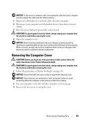
... follow the safety instructions in "Before You Begin" on its side with the computer cover facing up. 3 Remove the two screws securing the cover. While you begin any of the computer. CAUTION: To guard against electrical shock...4 Open the computer cover. NOTICE: Ensure that you are working on a level, protected surface to support the removed cover. NOTICE: Ensure that sufficient space exists to avoid scratching either the computer or the surface on which could harm... static electricity, which it is resting. 2 Lay your computer on page 101. Removing and Installing Parts 103
... follow the safety instructions in "Before You Begin" on its side with the computer cover facing up. 3 Remove the two screws securing the cover. While you begin any of the computer. CAUTION: To guard against electrical shock...4 Open the computer cover. NOTICE: Ensure that you are working on a level, protected surface to support the removed cover. NOTICE: Ensure that sufficient space exists to avoid scratching either the computer or the surface on which could harm... static electricity, which it is resting. 2 Lay your computer on page 101. Removing and Installing Parts 103

Owner's Manual
Page 104
1 2 1 computer cover 2 front of computer 4 Release the computer cover by pulling it away from the front of the computer and lifting it up. 5 Set the cover aside in a secure location. 104 Removing and Installing Parts
1 2 1 computer cover 2 front of computer 4 Release the computer cover by pulling it away from the front of the computer and lifting it up. 5 Set the cover aside in a secure location. 104 Removing and Installing Parts
Owner's Manual
Page 105
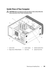
Inside View of Your Computer CAUTION: Before you begin any of the procedures in this section, follow the safety instructions in the Product Information Guide. 1 2 3 4 6 5 1 optical drive 2 power supply 3 optional optical drive 4 floppy drive or Media Reader 5 hard drive 6 optional hard drive Removing and Installing Parts 105
Inside View of Your Computer CAUTION: Before you begin any of the procedures in this section, follow the safety instructions in the Product Information Guide. 1 2 3 4 6 5 1 optical drive 2 power supply 3 optional optical drive 4 floppy drive or Media Reader 5 hard drive 6 optional hard drive Removing and Installing Parts 105
Owner's Manual
Page 106
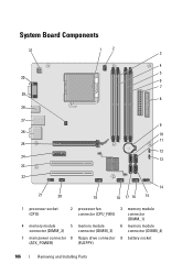
System Board Components 31 30 29 28 1 2 3 4 5 6 7 8 27 9 26 10 11 25 12 24 13 23 22 21 20 14 19 18 17 16 15 1 processor socket (CPU) 2 processor fan connector (CPU_FAN) 3 memory module connector (DIMM_1) 4 memory module 5 memory module 6 memory module connector (DIMM_2) connector (DIMM_3) connector (DIMM_4) 7 main power connector 8 floppy drive connector 9 battery socket (ATX_POWER) (FLOPPY) 106 Removing and Installing Parts
System Board Components 31 30 29 28 1 2 3 4 5 6 7 8 27 9 26 10 11 25 12 24 13 23 22 21 20 14 19 18 17 16 15 1 processor socket (CPU) 2 processor fan connector (CPU_FAN) 3 memory module connector (DIMM_1) 4 memory module 5 memory module 6 memory module connector (DIMM_2) connector (DIMM_3) connector (DIMM_4) 7 main power connector 8 floppy drive connector 9 battery socket (ATX_POWER) (FLOPPY) 106 Removing and Installing Parts
Owner's Manual
Page 108
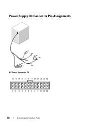
Power Supply DC Connector Pin Assignments DC Power Connector P1 13 14 15 16 17 18 19 20 21 22 23 24 1 2 3 4 5 6 7 8 9 10 11 12 108 Removing and Installing Parts
Power Supply DC Connector Pin Assignments DC Power Connector P1 13 14 15 16 17 18 19 20 21 22 23 24 1 2 3 4 5 6 7 8 9 10 11 12 108 Removing and Installing Parts
Owner's Manual
Page 109
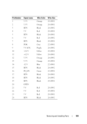
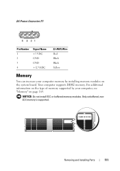
Pin Number 1 2 3 4 5 6 7 8 9 10 11 12 13 14 15 16 17 18 19 20 21 22 23 24 Signal name 3.3 V 3.3 V RTN 5 V RTN 5 V RTN POK 5 V AUX +12 V +12 V 3.3 V 3.3 V -12 V RTN PS_ON RTN RTN RTN OPEN 5 V 5 V 5 V RTN Wire Color Orange Orange Black Red Black Red Black Gray Purple Yellow Yellow Orange Orange Blue Black Green Black Black Black Wire Size 20 AWG 20 AWG 20 AWG 20 AWG 20 AWG 20 AWG 20 AWG 22 AWG 20 AWG 20 AWG 20 AWG 20 AWG 20 AWG 22 AWG 20 AWG 22 AWG 20 AWG 20 AWG 20 AWG Red Red Red Black 20 AWG 20 AWG 20 AWG 20 AWG Removing and Installing Parts 109
Pin Number 1 2 3 4 5 6 7 8 9 10 11 12 13 14 15 16 17 18 19 20 21 22 23 24 Signal name 3.3 V 3.3 V RTN 5 V RTN 5 V RTN POK 5 V AUX +12 V +12 V 3.3 V 3.3 V -12 V RTN PS_ON RTN RTN RTN OPEN 5 V 5 V 5 V RTN Wire Color Orange Orange Black Red Black Red Black Gray Purple Yellow Yellow Orange Orange Blue Black Green Black Black Black Wire Size 20 AWG 20 AWG 20 AWG 20 AWG 20 AWG 20 AWG 20 AWG 22 AWG 20 AWG 20 AWG 20 AWG 20 AWG 20 AWG 22 AWG 20 AWG 22 AWG 20 AWG 20 AWG 20 AWG Red Red Red Black 20 AWG 20 AWG 20 AWG 20 AWG Removing and Installing Parts 109
Owner's Manual
Page 110
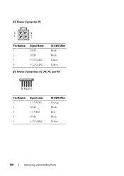
DC Power Connector P2 3 4 1 2 Pin Number 1 2 3 4 Signal Name GND GND +12 VADC +12 VADC 18-AWG Wire Black Black Yellow Yellow DC Power Connectors P3, P4, P5, and P6 Pin Number 1 2 3 4 5 Signal name +3.3 VDC GND +5 VDC GND +12 VBDC 18-AWG Wire Orange Black Red Black White 110 Removing and Installing Parts
DC Power Connector P2 3 4 1 2 Pin Number 1 2 3 4 Signal Name GND GND +12 VADC +12 VADC 18-AWG Wire Black Black Yellow Yellow DC Power Connectors P3, P4, P5, and P6 Pin Number 1 2 3 4 5 Signal name +3.3 VDC GND +5 VDC GND +12 VBDC 18-AWG Wire Orange Black Red Black White 110 Removing and Installing Parts
Owner's Manual
Page 111
DC Power Connector P7 Pin Number 1 2 3 4 Signal Name +5 VDC GND GND +12 VADC 22-AWG Wire Red Black Black Yellow Memory You can increase your computer memory by your computer, see "Memory" on the system board. For additional information on the type of memory supported by installing memory modules on page 169. Only unbuffered, nonECC memory is supported. Removing and Installing Parts 111 NOTICE: Do not install ECC or buffered memory modules. Your computer supports DDR2 memory.
DC Power Connector P7 Pin Number 1 2 3 4 Signal Name +5 VDC GND GND +12 VADC 22-AWG Wire Red Black Black Yellow Memory You can increase your computer memory by your computer, see "Memory" on the system board. For additional information on the type of memory supported by installing memory modules on page 169. Only unbuffered, nonECC memory is supported. Removing and Installing Parts 111 NOTICE: Do not install ECC or buffered memory modules. Your computer supports DDR2 memory.

Owner's Manual
Page 112
....) For example, if you must install it in connector DIMM_1. • For best performance, memory modules should be installed in pairs of memory modules in connectors DIMM_3 and DIMM_4 112 Removing and Installing Parts If the memory modules are not installed in connectors DIMM_1 and DIMM_2 2 Pair... B: matched pair of matched memory size, speed, and technology. If a single DIMM is installed, you install a mixed pair of DDR2 533-MHz...
....) For example, if you must install it in connector DIMM_1. • For best performance, memory modules should be installed in pairs of memory modules in connectors DIMM_3 and DIMM_4 112 Removing and Installing Parts If the memory modules are not installed in connectors DIMM_1 and DIMM_2 2 Pair... B: matched pair of matched memory size, speed, and technology. If a single DIMM is installed, you install a mixed pair of DDR2 533-MHz...
Owner's Manual
Page 113
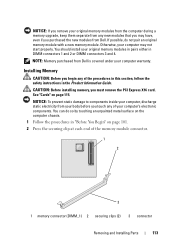
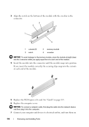
...Guide. Otherwise, your computer warranty. CAUTION: Before installing memory, you touch any of the memory module connector. 1 2 3 1 memory connector (DIMM_1) 2 securing clips (2) 3 connector Removing and Installing Parts 113 NOTE: Memory purchased from Dell is covered under your computer may have, even... if you purchased the new modules from your body before you must remove the PCI Express X16 card. If possible, do ...
...Guide. Otherwise, your computer warranty. CAUTION: Before installing memory, you touch any of the memory module connector. 1 2 3 1 memory connector (DIMM_1) 2 securing clips (2) 3 connector Removing and Installing Parts 113 NOTE: Memory purchased from Dell is covered under your computer may have, even... if you purchased the new modules from your body before you must remove the PCI Express X16 card. If possible, do ...
Owner's Manual
Page 114
... the computer. 7 Connect your computer and devices to electrical outlets, and turn them on page 115. 6 Replace the computer cover. See "Cards" on . 114 Removing and Installing Parts If you apply equal force to each end of the module. 4 Insert the module into the connector until the module snaps into position. 3 Align the...
... the computer. 7 Connect your computer and devices to electrical outlets, and turn them on page 115. 6 Replace the computer cover. See "Cards" on . 114 Removing and Installing Parts If you apply equal force to each end of the module. 4 Insert the module into the connector until the module snaps into position. 3 Align the...
Owner's Manual
Page 115
...chassis. 1 Follow the procedures in "Before You Begin" on page 115. Removing and Installing Parts 115 See "Cards" on the computer chassis. Removing Memory CAUTION: Before you must remove the PCI Express X16 card. Your Dell™ computer provides the following slots for PCI and PCI Express cards: &#...106 for card slot location. CAUTION: Before removing memory, you begin any of memory (RAM) listed. 8 Right-click the My Computer icon and click Properties. 9 Click the General tab. 10 To verify that the memory is installed correctly, check the amount of the procedures ...
...chassis. 1 Follow the procedures in "Before You Begin" on page 115. Removing and Installing Parts 115 See "Cards" on the computer chassis. Removing Memory CAUTION: Before you must remove the PCI Express X16 card. Your Dell™ computer provides the following slots for PCI and PCI Express cards: &#...106 for card slot location. CAUTION: Before removing memory, you begin any of memory (RAM) listed. 8 Right-click the My Computer icon and click Properties. 9 Click the General tab. 10 To verify that the memory is installed correctly, check the amount of the procedures ...
Owner's Manual
Page 116
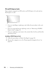
..." on page 101. 2 Remove the computer cover. Installing a PCI/PCI Express Card 1 Follow the procedures in the next section. • If you are removing but not replacing a card, see "Removing a PCI/PCI Express Card" on page 103. 116 Removing and Installing Parts See "Removing the Computer Cover" on page... 121. • If you are replacing a card, remove the current driver for the card from the...
..." on page 101. 2 Remove the computer cover. Installing a PCI/PCI Express Card 1 Follow the procedures in the next section. • If you are removing but not replacing a card, see "Removing a PCI/PCI Express Card" on page 103. 116 Removing and Installing Parts See "Removing the Computer Cover" on page... 121. • If you are replacing a card, remove the current driver for the card from the...
Owner's Manual
Page 117
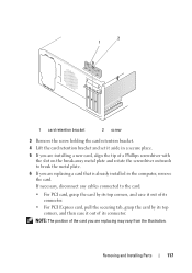
...Remove the screw holding the card retention bracket. 4 Lift the card retention bracket and set it out of the card you are replacing may vary from the illustration. If necessary, disconnect any cables connected to break the metal plate. 6 If you are replacing a card that is already installed... in a secure place. 5 If you are installing a new card, align the tip of a Phillips screwdriver with the slot on the..., and then ease it aside in the computer, remove the card. Removing and Installing Parts 117
...Remove the screw holding the card retention bracket. 4 Lift the card retention bracket and set it out of the card you are replacing may vary from the illustration. If necessary, disconnect any cables connected to break the metal plate. 6 If you are replacing a card that is already installed... in a secure place. 5 If you are installing a new card, align the tip of a Phillips screwdriver with the slot on the..., and then ease it aside in the computer, remove the card. Removing and Installing Parts 117
Owner's Manual
Page 118
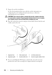
...caught outside of slot 9 If you are connected to unplug your computer. CAUTION: Some network adapters automatically start the computer when they are installing the PCI Express card into the x16 card connector, position the card so the securing slot is fully seated in the connector and press ... that the card is aligned with the card for information on configuring the card, making internal connections, or otherwise customizing it for installation. To guard against electrical shock, be sure to a network. Ensure that came with the securing tab. 118 Removing and Installing Parts
...caught outside of slot 9 If you are connected to unplug your computer. CAUTION: Some network adapters automatically start the computer when they are installing the PCI Express card into the x16 card connector, position the card so the securing slot is fully seated in the connector and press ... that the card is aligned with the card for information on configuring the card, making internal connections, or otherwise customizing it for installation. To guard against electrical shock, be sure to a network. Ensure that came with the securing tab. 118 Removing and Installing Parts
Owner's Manual
Page 119
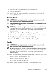
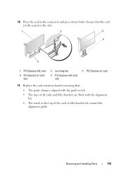
Removing and Installing Parts 119 10 Place the card in the top of the card or filler bracket fits around the alignment guide. Ensure that the card is fully seated in the slot. 1 2 3 4 5 1 PCI Express x16 card 4 PCI Express x1 card slot 2 securing tab 5 PCI Express x16 card slot 3 PCI Express x1 card 11 Replace the card retention bracket ensuring that: • The guide clamp is aligned with the guide notch. • The tops of all cards and filler brackets are flush with the alignment bar. • The notch in the connector and press down firmly.
Removing and Installing Parts 119 10 Place the card in the top of the card or filler bracket fits around the alignment guide. Ensure that the card is fully seated in the slot. 1 2 3 4 5 1 PCI Express x16 card 4 PCI Express x1 card slot 2 securing tab 5 PCI Express x16 card slot 3 PCI Express x1 card 11 Replace the card retention bracket ensuring that: • The guide clamp is aligned with the guide notch. • The tops of all cards and filler brackets are flush with the alignment bar. • The notch in the connector and press down firmly.


