
Hardware Manual
Page 4
... the System Setup Program 56 Responding to Error Messages 56 Using the System Setup Program Navigation Keys 56 System Setup Options 57 Main Screen 57 Memory Settings Screen 59 Processor Settings Screen 60 SATA Settings Screen 60 Boot Settings Screen 61 Integrated Devices Screen 62 PCI IRQ Assignments Screen 63 Serial...
... the System Setup Program 56 Responding to Error Messages 56 Using the System Setup Program Navigation Keys 56 System Setup Options 57 Main Screen 57 Memory Settings Screen 59 Processor Settings Screen 60 SATA Settings Screen 60 Boot Settings Screen 61 Integrated Devices Screen 62 PCI IRQ Assignments Screen 63 Serial...
Hardware Manual
Page 6
... Installing the Internal SD Flash Card 90 Removing the Internal SD Flash Card 91 Internal USB Memory Key 91 Internal USB Cable 93 Removing the Internal USB Cable 93 Installing the Internal USB Cable 93 Integrated Dell Remote Access Controller 6 (iDRAC6) Enterprise Card (Optional 94 Installing an iDRAC6 Enterprise Card 94 Removing...
... Installing the Internal SD Flash Card 90 Removing the Internal SD Flash Card 91 Internal USB Memory Key 91 Internal USB Cable 93 Removing the Internal USB Cable 93 Installing the Internal USB Cable 93 Integrated Dell Remote Access Controller 6 (iDRAC6) Enterprise Card (Optional 94 Installing an iDRAC6 Enterprise Card 94 Removing...
Hardware Manual
Page 7
... Expansion-Card Riser 2 126 Removing Expansion-Card Riser 2 From the Expansion-Card Bracket 127 Replacing the Riser 2 Board on the Expansion-Card Bracket 128 System Memory 129 General Memory Module Installation Guidelines 129 Mode-Specific Guidelines 131 Installing...
... Expansion-Card Riser 2 126 Removing Expansion-Card Riser 2 From the Expansion-Card Bracket 127 Replacing the Riser 2 Board on the Expansion-Card Bracket 128 System Memory 129 General Memory Module Installation Guidelines 129 Mode-Specific Guidelines 131 Installing...
Hardware Manual
Page 8
Removing Memory Modules 136 Processors 137 Removing a Processor 137 Installing a Processor 140 System Battery 141 Replacing the System Battery 141 Control Panel Assembly 143 Removing the Control ...
Removing Memory Modules 136 Processors 137 Removing a Processor 137 Installing a Processor 140 System Battery 141 Replacing the System Battery 141 Control Panel Assembly 143 Removing the Control ...
Hardware Manual
Page 9
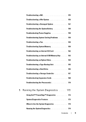
... Internal SD Card 162 Troubleshooting an Internal USB Memory Key . . . . . 163 Troubleshooting an Optical Drive 164 Troubleshooting a Tape Backup Unit 165 Troubleshooting a Hard Drive 166 Troubleshooting a Storage Controller 167 Troubleshooting Expansion Cards 168 Troubleshooting the Processor(s 170 5 Running the System Diagnostics . . . . . 173 Using Dell™ PowerEdge™ Diagnostics 173 System Diagnostics Features 173...
... Internal SD Card 162 Troubleshooting an Internal USB Memory Key . . . . . 163 Troubleshooting an Optical Drive 164 Troubleshooting a Tape Backup Unit 165 Troubleshooting a Hard Drive 166 Troubleshooting a Storage Controller 167 Troubleshooting Expansion Cards 168 Troubleshooting the Processor(s 170 5 Running the System Diagnostics . . . . . 173 Using Dell™ PowerEdge™ Diagnostics 173 System Diagnostics Features 173...
Hardware Manual
Page 13
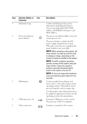
...-out label panel for five seconds. The ports are USB 2.0-complaint. Connects a monitor to the system is turned off the system using the end of memory installed in the system.
...-out label panel for five seconds. The ports are USB 2.0-complaint. Connects a monitor to the system is turned off the system using the end of memory installed in the system.
Hardware Manual
Page 20
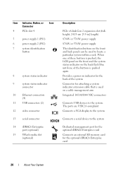
... Connects a VGA display to the system Connects a serial device to the system Dedicated management port for the optional iDRAC6 Enterprise card Connects an external SD memory card for the back of the buttons is used to the system.
... Connects a VGA display to the system Connects a serial device to the system Dedicated management port for the optional iDRAC6 Enterprise card Connects an external SD memory card for the back of the buttons is used to the system.
Hardware Manual
Page 24
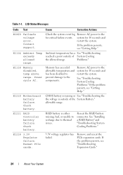
... system for critical failure events. Ambient temperature has a See "Troubleshooting reached a point outside of System Cooling the allowed range. Memory has exceeded allowable temperature and has been disabled to prevent damage to the system for 10 seconds and restart the system. Remove AC... problem persists, see "Getting Help." Problems." LCD Status Messages Code Text E1000 Failsafe voltage error. E1216 3.3V Regulator failure. E1116 Memory disabled, temp above range. CMOS battery is missing or See "Troubleshooting the the voltage is either missing, bad, or unable to ...
... system for critical failure events. Ambient temperature has a See "Troubleshooting reached a point outside of System Cooling the allowed range. Memory has exceeded allowable temperature and has been disabled to prevent damage to the system for 10 seconds and restart the system. Remove AC... problem persists, see "Getting Help." Problems." LCD Status Messages Code Text E1000 Failsafe voltage error. E1216 3.3V Regulator failure. E1116 Memory disabled, temp above range. CMOS battery is missing or See "Troubleshooting the the voltage is either missing, bad, or unable to ...

Hardware Manual
Page 25
... the Processor(s)." A power fault was detected Remove AC power to the system for 10 seconds and processor(s). Reseat DIMMs. Reseat the memory modules. Call support. If the problem persists, see "Getting Help." RPM of specified fan is outside of intended operating range. LCD... to the when powering up the system for 10 seconds and restart the system. About Your System 25 Reseat CPU. E122D Memory One of the on-board voltage regulators failed. See "Troubleshooting System Cooling Problems." Specified processor VCORE voltage regulator has failed. ...
... the Processor(s)." A power fault was detected Remove AC power to the system for 10 seconds and processor(s). Reseat DIMMs. Reseat the memory modules. Call support. If the problem persists, see "Getting Help." RPM of specified fan is outside of intended operating range. LCD... to the when powering up the system for 10 seconds and restart the system. About Your System 25 Reseat CPU. E122D Memory One of the on-board voltage regulators failed. See "Troubleshooting System Cooling Problems." Specified processor VCORE voltage regulator has failed. ...
Hardware Manual
Page 32
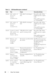
... see "Getting Help." E1A1D Control panel USB cable not detected. Reseat the cable. the memory modules. Error failure. E2012 Memory configured but is unusable. Check DIMMs. The system BIOS failed to the control panel is configuration... See "Installing Memory Modules" or "Troubleshooting System Memory." See "Troubleshooting System Memory." E2013 BIOS unable to shadow memory. E2011 Memory Memory detected, but is missing or bad. See "Troubleshooting System Memory." 32 About Your System E2010 Memory not detected. detected during memory Check DIMMs. configuration...
... see "Getting Help." E1A1D Control panel USB cable not detected. Reseat the cable. the memory modules. Error failure. E2012 Memory configured but is unusable. Check DIMMs. The system BIOS failed to the control panel is configuration... See "Installing Memory Modules" or "Troubleshooting System Memory." See "Troubleshooting System Memory." E2013 BIOS unable to shadow memory. E2011 Memory Memory detected, but is missing or bad. See "Troubleshooting System Memory." 32 About Your System E2010 Memory not detected. detected during memory Check DIMMs. configuration...
Hardware Manual
Page 34
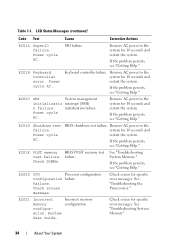
...restart the system. If the problem persists, see "Getting Help." Check screen for specific error messages. See "Troubleshooting System Memory". 34 About Your System Remove AC power to the system for 10 seconds and restart the system. Power cycle AC....Processor configuration configuration failure. If the problem persists, see "Getting Help." Check screen message. Review User Guide. E201E POST memory BIOS POST memory test test failure. SIO failure. If the problem persists, see "Getting Help." Power cycle AC. initialization failure. Keyboard controller...
...restart the system. If the problem persists, see "Getting Help." Check screen for specific error messages. See "Troubleshooting System Memory". 34 About Your System Remove AC power to the system for 10 seconds and restart the system. Power cycle AC....Processor configuration configuration failure. If the problem persists, see "Getting Help." Check screen message. Review User Guide. E201E POST memory BIOS POST memory test test failure. SIO failure. If the problem persists, see "Getting Help." Power cycle AC. initialization failure. Keyboard controller...
Hardware Manual
Page 35
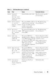
... has determined restart the system. E2110 Multibit Error on DIMM ## & ##. The system BIOS has Remove AC power to mirror memory. System cover has been removed. Check chassis cover. LCD Status Messages (continued) Code Text Cause Corrective Actions E2022 General failure ...screen message. because of the mirror has had a multi-bit System Memory." E2111 SBE log disabled on DIMM ##. see "Troubleshooting System Memory." memory module implicated by the BIOS. Reseat DIMM. Information only. The memory module in slot See "Troubleshooting "##" has had too many errors....
... has determined restart the system. E2110 Multibit Error on DIMM ## & ##. The system BIOS has Remove AC power to mirror memory. System cover has been removed. Check chassis cover. LCD Status Messages (continued) Code Text Cause Corrective Actions E2022 General failure ...screen message. because of the mirror has had a multi-bit System Memory." E2111 SBE log disabled on DIMM ##. see "Troubleshooting System Memory." memory module implicated by the BIOS. Reseat DIMM. Information only. The memory module in slot See "Troubleshooting "##" has had too many errors....
Hardware Manual
Page 37
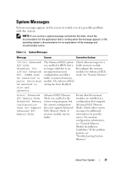
...-bit Advanced The Advanced ECC option Check other system messages for additional information for the application that supports Advanced ECC Memory Mode. Memory configuration does not support Advanced ECC Memory Mode. Ensure that the memory modules are installed in the system setup program, but is running when the message appears or the operating system...
...-bit Advanced The Advanced ECC option Check other system messages for additional information for the application that supports Advanced ECC Memory Mode. Memory configuration does not support Advanced ECC Memory Mode. Ensure that the memory modules are installed in the system setup program, but is running when the message appears or the operating system...
Hardware Manual
Page 38
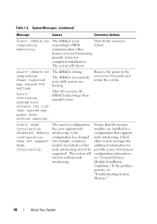
... iDRAC6 takes longer than normal to BIOS communication either because it is hung. If the problem persists, see "General Memory Module Installation Guidelines." Rebooting. Wait for 10 seconds and restart the system. Alert! The system will reboot. Power ...interleaving cannot be supported. Alert! Check other system messages for additional information for example, a memory module has failed) so that supports node interleaving. Table 1-2. The memory configuration does not support node interleaving, or the configuration has changed (for possible causes. iDRAC6...
... iDRAC6 takes longer than normal to BIOS communication either because it is hung. If the problem persists, see "General Memory Module Installation Guidelines." Rebooting. Wait for 10 seconds and restart the system. Alert! The system will reboot. Power ...interleaving cannot be supported. Alert! Check other system messages for additional information for example, a memory module has failed) so that supports node interleaving. Table 1-2. The memory configuration does not support node interleaving, or the configuration has changed (for possible causes. iDRAC6...
Hardware Manual
Page 39
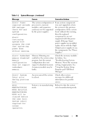
...with this power supply. The system configuration of manufacturing mode. If the system boots without warning. Memory configuration does not support redundant memory. Alert! Check other system messages for additional information for normal operation. MANUFACTURING MODE will be supported...supplies are not supported with the High Output power supplies to take the system mode. See "Power Supplies." Redundant memory disabled! System Messages (continued) Message Causes Corrective Actions Alert! Power required exceeds PSU wattage. Alert! BIOS MANUFACTURING ...
...with this power supply. The system configuration of manufacturing mode. If the system boots without warning. Memory configuration does not support redundant memory. Alert! Check other system messages for additional information for normal operation. MANUFACTURING MODE will be supported...supplies are not supported with the High Output power supplies to take the system mode. See "Power Supplies." Redundant memory disabled! System Messages (continued) Message Causes Corrective Actions Alert! Power required exceeds PSU wattage. Alert! BIOS MANUFACTURING ...
Hardware Manual
Page 40
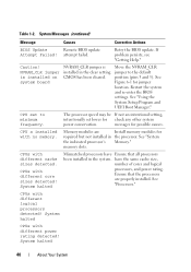
... Move the NVRAM_CLR installed in the processor. Restart the system and re-enter the BIOS settings. messages for jumper location. CPUs with no memory. If problem persists, see "Getting Help." position (pins 3 and 5). CPU set lower for required but not installed in the clear ...setting. CPU x installed with different cache sizes detected. memory slots. CPUs with different power rating detected! The processor speed may be If not an intentional setting, intentionally set to the default CMOS ...
... Move the NVRAM_CLR installed in the processor. Restart the system and re-enter the BIOS settings. messages for jumper location. CPUs with no memory. If problem persists, see "Getting Help." position (pins 3 and 5). CPU set lower for required but not installed in the clear ...setting. CPU x installed with different cache sizes detected. memory slots. CPUs with different power rating detected! The processor speed may be If not an intentional setting, intentionally set to the default CMOS ...
Hardware Manual
Page 41
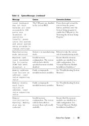
... Management Shared NIC= The OS NIC interface is set in a valid configuration. Error 8602 Auxiliary Device Failure. Verify that the memory modules are securely attached to correct connectors. System Messages (continued) Message Causes Corrective Actions Current boot mode The system failed to boot...If a problem is non-UEFI. About Your System 41 because UEFI boot mode is Please ensure enabled in management tools. Invalid memory configuration on each processor must be identical. Mouse or keyboard cable is set correctly and that the mouse or keyboard is available...
... Management Shared NIC= The OS NIC interface is set in a valid configuration. Error 8602 Auxiliary Device Failure. Verify that the memory modules are securely attached to correct connectors. System Messages (continued) Message Causes Corrective Actions Current boot mode The system failed to boot...If a problem is non-UEFI. About Your System 41 because UEFI boot mode is Please ensure enabled in management tools. Invalid memory configuration on each processor must be identical. Mouse or keyboard cable is set correctly and that the mouse or keyboard is available...
Hardware Manual
Page 43
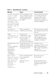
... word logic failure at address, read value expecting value Faulty or improperly See "Troubleshooting System installed memory modules. Ensure that the memory modules are disabled. See "General Memory Module Installation Guidelines." Maximum rank count exceeded. Memory Initialization Warning: Memory size may not work because all user accessible USB ports are installed in a valid configuration. If...
... word logic failure at address, read value expecting value Faulty or improperly See "Troubleshooting System installed memory modules. Ensure that the memory modules are disabled. See "General Memory Module Installation Guidelines." Maximum rank count exceeded. Memory Initialization Warning: Memory size may not work because all user accessible USB ports are installed in a valid configuration. If...
Hardware Manual
Page 44
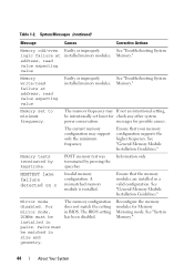
... may support only the minimum frequency. Reconfigure the memory modules for possible causes. Memory." Ensure that the memory modules are installed in BIOS. MEMTEST lane failure detected on x Invalid memory configuration. A mismatched memory module is installed. See "Troubleshooting System Memory." Pairs must be matched in pairs. Memory write/read failure at address, read value expecting value Faulty...
... may support only the minimum frequency. Reconfigure the memory modules for possible causes. Memory." Ensure that the memory modules are installed in BIOS. MEMTEST lane failure detected on x Invalid memory configuration. A mismatched memory module is installed. See "Troubleshooting System Memory." Pairs must be matched in pairs. Memory write/read failure at address, read value expecting value Faulty...
Hardware Manual
Page 46
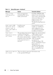
... connected. System Messages (continued) Message Causes Corrective Actions Plug & Play Configuration Error Error encountered in a valid configuration. Invalid memory configuration. See "General Memory Module Installation Guidelines." optical drive, or USB device, Ensure that the memory modules are properly or the requested sector is no device connected Information only. Read fault Requested sector not...
... connected. System Messages (continued) Message Causes Corrective Actions Plug & Play Configuration Error Error encountered in a valid configuration. Invalid memory configuration. See "General Memory Module Installation Guidelines." optical drive, or USB device, Ensure that the memory modules are properly or the requested sector is no device connected Information only. Read fault Requested sector not...


