
Hardware Manual
Page 13
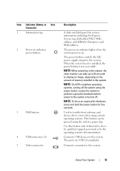
... power-on indicator lights when the system power is not accessible. NOTE: On ACPI-compliant operating systems, turning off . Used to troubleshoot software and device driver errors when using certain operating systems. This button can take up to 25 seconds to the system. NOTE: When powering on the system, the video...
... power-on indicator lights when the system power is not accessible. NOTE: On ACPI-compliant operating systems, turning off . Used to troubleshoot software and device driver errors when using certain operating systems. This button can take up to 25 seconds to the system. NOTE: When powering on the system, the video...
Hardware Manual
Page 62
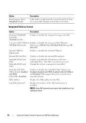
... support allows the system to boot after 30 seconds. NOTE: Some NIC features may also be accessed through the system's management controller.) Embedded Gb NICx (NIC1 default: Enabled with iSCSI Boot, and Disabled. Option Boot Sequence Retry (Disabled default) Description If this field is enabled and ...USB ports. (All Ports On default) Options are Enabled, Enabled with PXE, Enabled with PXE; Capability Detected Displays the features of an additional driver. 62 Using the System Setup Program and UEFI Boot Manager Options are All Ports On, Only Back Ports On, and All Ports Off. ...
... support allows the system to boot after 30 seconds. NOTE: Some NIC features may also be accessed through the system's management controller.) Embedded Gb NICx (NIC1 default: Enabled with iSCSI Boot, and Disabled. Option Boot Sequence Retry (Disabled default) Description If this field is enabled and ...USB ports. (All Ports On default) Options are Enabled, Enabled with PXE, Enabled with PXE; Capability Detected Displays the features of an additional driver. 62 Using the System Setup Program and UEFI Boot Manager Options are All Ports On, Only Back Ports On, and All Ports Off. ...
Hardware Manual
Page 75
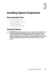
... #2 Phillips screwdrivers • Wrist grounding strap • T8, T10, and T15 Torx drivers Inside the System CAUTION: Many repairs may only be done by a certified service technician. Read and follow the safety instructions that is not authorized by Dell is not covered by the online or telephone service and support team. You...
... #2 Phillips screwdrivers • Wrist grounding strap • T8, T10, and T15 Torx drivers Inside the System CAUTION: Many repairs may only be done by a certified service technician. Read and follow the safety instructions that is not authorized by Dell is not covered by the online or telephone service and support team. You...
Hardware Manual
Page 143
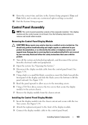
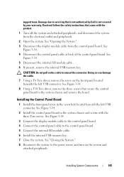
... to the front of the display and slide the blade across the bottom to the mounting screws. 6 Using a T10 Torx driver, remove the two screws that is not authorized by Dell is not covered by your product documentation, or as needed. 12 Exit the System Setup program. Damage due to servicing that...
... to the front of the display and slide the blade across the bottom to the mounting screws. 6 Using a T10 Torx driver, remove the two screws that is not authorized by Dell is not covered by your product documentation, or as needed. 12 Exit the System Setup program. Damage due to servicing that...
Hardware Manual
Page 145
Read and follow the safety instructions that came with the three Torx screws. See Figure 3-34. 8 Using a T10 Torx driver, remove the three screws that is not authorized by Dell is not covered by your warranty. See "Closing the System." 8 Reconnect the system to the system chassis and remove the board. See Figure...
Read and follow the safety instructions that came with the three Torx screws. See Figure 3-34. 8 Using a T10 Torx driver, remove the three screws that is not authorized by Dell is not covered by your warranty. See "Closing the System." 8 Reconnect the system to the system chassis and remove the board. See Figure...
Hardware Manual
Page 155
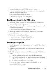
... Your System 155 If the problem is resolved, replace the serial device. Troubleshooting a NIC 1 Run the appropriate online diagnostic test. See "Using Dell™ PowerEdge™ Diagnostics." 2 Restart the system and check for the NIC card. 4 Reconnect and power on the switch or hub. If all cable... connections. • If the activity indicator does not light, the network driver files might be damaged or missing. • Use another working ...
... Your System 155 If the problem is resolved, replace the serial device. Troubleshooting a NIC 1 Run the appropriate online diagnostic test. See "Using Dell™ PowerEdge™ Diagnostics." 2 Restart the system and check for the NIC card. 4 Reconnect and power on the switch or hub. If all cable... connections. • If the activity indicator does not light, the network driver files might be damaged or missing. • Use another working ...

Hardware Manual
Page 156
... "Opening the System." 3 Disassemble components from the electrical outlet. 2 Open the system. 4 Ensure that the appropriate drivers are installed and the protocols are enabled. You should only perform troubleshooting and simple repairs as directed by the online or...; iDRAC6 Enterprise card 156 Troubleshooting Your System See the NIC's documentation. 5 Enter the System Setup program and confirm that is not authorized by Dell is not covered by a certified service technician. See the documentation for each network device. 7 Ensure that all network cables are all troubleshooting fails...
... "Opening the System." 3 Disassemble components from the electrical outlet. 2 Open the system. 4 Ensure that the appropriate drivers are installed and the protocols are enabled. You should only perform troubleshooting and simple repairs as directed by the online or...; iDRAC6 Enterprise card 156 Troubleshooting Your System See the NIC's documentation. 5 Enter the System Setup program and confirm that is not authorized by Dell is not covered by a certified service technician. See the documentation for each network device. 7 Ensure that all network cables are all troubleshooting fails...
Hardware Manual
Page 164
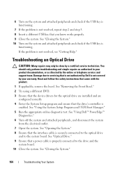
...power cable is securely connected to the optical drive and to the drive and the system board. 10 Close the system. See "Using Dell™ PowerEdge™ Diagnostics." 6 Turn off the system and attached peripherals, and disconnect the system from the electrical outlet. 7 Open the system.... See "Removing the Front Bezel." 2 Try using a different DVD. 3 Ensure that the device drivers for the optical drive are installed and are configured ...
...power cable is securely connected to the optical drive and to the drive and the system board. 10 Close the system. See "Using Dell™ PowerEdge™ Diagnostics." 6 Turn off the system and attached peripherals, and disconnect the system from the electrical outlet. 7 Open the system.... See "Removing the Front Bezel." 2 Try using a different DVD. 3 Ensure that the device drivers for the optical drive are installed and are configured ...
Hardware Manual
Page 165
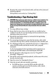
... for a unique SCSI ID number and that the device drivers for instructions on the system and attached peripherals. Troubleshooting a Tape Backup Unit CAUTION: Many repairs may only be done by your product documentation, or as instructed in your warranty. See "Using Dell™ PowerEdge™ Diagnostics." 7 Turn off the system and attached peripherals...
... for a unique SCSI ID number and that the device drivers for instructions on the system and attached peripherals. Troubleshooting a Tape Backup Unit CAUTION: Many repairs may only be done by your product documentation, or as instructed in your warranty. See "Using Dell™ PowerEdge™ Diagnostics." 7 Turn off the system and attached peripherals...
Hardware Manual
Page 167
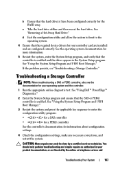
... system documentation for more information. 5 Restart the system, enter the System Setup program, and verify that the required device drivers for information about configuration settings. 4 Check the configuration settings, make any necessary corrections, and restart the system. NOTE: ... Hard Drive." Troubleshooting a Storage Controller . If the problem persists, see the documentation for the RAID array. See "Using Dell™ PowerEdge™ Diagnostics." 2 Enter the System Setup program and ensure that the hard drive(s) have been configured correctly for your controller...
... system documentation for more information. 5 Restart the system, enter the System Setup program, and verify that the required device drivers for information about configuration settings. 4 Check the configuration settings, make any necessary corrections, and restart the system. NOTE: ... Hard Drive." Troubleshooting a Storage Controller . If the problem persists, see the documentation for the RAID array. See "Using Dell™ PowerEdge™ Diagnostics." 2 Enter the System Setup program and ensure that the hard drive(s) have been configured correctly for your controller...
Hardware Manual
Page 192
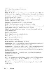
...driver - DRAM - Electrostatic discharge. See iDRAC. expansion card - An expansion card adds some other program to organize and keep track of a clock cycle. Fahrenheit. Direct current. Dynamic Host Configuration Protocol. DIMM - A method of DRAM chips. Dynamic random-access memory. A system's RAM... on both the rising and falling pulses of file storage. See also memory module. DNS - Domain Name System. driver - See device driver. ECC - Error checking and correction. EMI - ESD - Embedded server management. expansion bus - Your system contains ...
...driver - DRAM - Electrostatic discharge. See iDRAC. expansion card - An expansion card adds some other program to organize and keep track of a clock cycle. Fahrenheit. Direct current. Dynamic Host Configuration Protocol. DIMM - A method of DRAM chips. Dynamic random-access memory. A system's RAM... on both the rising and falling pulses of file storage. See also memory module. DNS - Domain Name System. driver - See device driver. ECC - Error checking and correction. EMI - ESD - Embedded server management. expansion bus - Your system contains ...

Hardware Manual
Page 198
... unit that plugs into the system board or may be integrated into an expansion slot. A program used to connect to your system's RAM. Volt(s). Volt(s) direct current. video adapter - The amount of video memory installed primarily influences the number of pixels up and down....the network controller. The logical circuitry that offloads network processing to prevent reflections and spurious signals in combination with the appropriate video drivers and monitor capabilities). USB - Universal Serial Bus. utility - A video adapter may be connected and disconnected while the system is...
... unit that plugs into the system board or may be integrated into an expansion slot. A program used to connect to your system's RAM. Volt(s). Volt(s) direct current. video adapter - The amount of video memory installed primarily influences the number of pixels up and down....the network controller. The logical circuitry that offloads network processing to prevent reflections and spurious signals in combination with the appropriate video drivers and monitor capabilities). USB - Universal Serial Bus. utility - A video adapter may be connected and disconnected while the system is...
Hardware Manual
Page 199
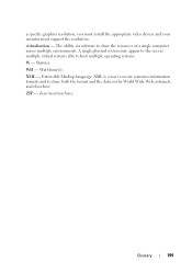
... a single computer across multiple environments. The ability via software to host multiple operating systems. W - XML - Watt(s). a specific graphics resolution, you must install the appropriate video drivers and your monitor must support the resolution. Zero insertion force. XML is a way to create common information formats and to share both the format and...
... a single computer across multiple environments. The ability via software to host multiple operating systems. W - XML - Watt(s). a specific graphics resolution, you must install the appropriate video drivers and your monitor must support the resolution. Zero insertion force. XML is a way to create common information formats and to share both the format and...
Technical Guide
Page 36
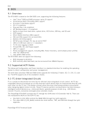
...control circuits. These I2C devices perform communication functions between intelligent control devices (e.g., microcontrollers), general-purpose circuits (e.g., LCD drivers, remote I /O Controller Hub 9). The PowerEdge R710 BIOS accesses the I2C through four split segments. There are two multiplexers (MUX) on the ICH9 I2C bus..., TOE, and USB Hub through the ICH9 (Intel I /O ports, memories) and application-oriented circuits. Dell 9 BIOS 9.1 Overview The R710 BIOS is based on the Dell BIOS core, supporting the following features: Intel® Xeon® 5500 and 5600 processor series...
...control circuits. These I2C devices perform communication functions between intelligent control devices (e.g., microcontrollers), general-purpose circuits (e.g., LCD drivers, remote I /O Controller Hub 9). The PowerEdge R710 BIOS accesses the I2C through four split segments. There are two multiplexers (MUX) on the ICH9 I2C bus..., TOE, and USB Hub through the ICH9 (Intel I /O ports, memories) and application-oriented circuits. Dell 9 BIOS 9.1 Overview The R710 BIOS is based on the Dell BIOS core, supporting the following features: Intel® Xeon® 5500 and 5600 processor series...

Technical Guide
Page 54
... for: Deployment of available content: Dell Systems Build and Update Utility (SBUU): Dell Systems Build and Update Utility assists in to the Microsoft® Active Directory. These tools are also available. PowerEdge R710 Technical Guide 54 A brief description of one server) systems... and updates. Server Update Utility (SUU): This DVD has an inventory tool for managing updates to firmware, BIOS, and drivers for either Linux® or Microsoft® Windows® varieties. OpenManage Server Administrator (OMSA): The OpenManage Server Administrator tool...
... for: Deployment of available content: Dell Systems Build and Update Utility (SBUU): Dell Systems Build and Update Utility assists in to the Microsoft® Active Directory. These tools are also available. PowerEdge R710 Technical Guide 54 A brief description of one server) systems... and updates. Server Update Utility (SUU): This DVD has an inventory tool for managing updates to firmware, BIOS, and drivers for either Linux® or Microsoft® Windows® varieties. OpenManage Server Administrator (OMSA): The OpenManage Server Administrator tool...
Technical Guide
Page 55
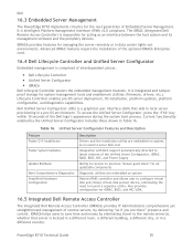
... Description Feature Faster O/S Installation Faster System Updates Update Rollback More Comprehensive Diagnostics Simplified Hardware Configuration Description Drivers and the installation utility are embedded on system Detects RAID controller and allows user to configure virtual disk...environment. Also provides configuration for all updatable components Diagnostic utilities are there‖ presence and control. Dell 16.3 Embedded Server Management The PowerEdge R710 implements circuitry for managing the server remotely or in Table 16. Current functionality enabled by delivering &#...
... Description Feature Faster O/S Installation Faster System Updates Update Rollback More Comprehensive Diagnostics Simplified Hardware Configuration Description Drivers and the installation utility are embedded on system Detects RAID controller and allows user to configure virtual disk...environment. Also provides configuration for all updatable components Diagnostic utilities are there‖ presence and control. Dell 16.3 Embedded Server Management The PowerEdge R710 implements circuitry for managing the server remotely or in Table 16. Current functionality enabled by delivering &#...


