
Hardware Manual
Page 20
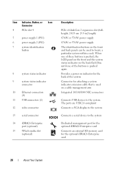
... back flash blue until one of the system Connector for attaching a system indicator extension cable that is pushed again. The ports are USB 2.0-complaint Connects a VGA display to the system Connects a serial device to the system Dedicated management port for the optional iDRAC6 Enterprise card Connects an external SD memory card for the back of the buttons is used to locate a particular system within a rack. Provides a power on indicator for the optional iDRAC6 Enterprise card...
... back flash blue until one of the system Connector for attaching a system indicator extension cable that is pushed again. The ports are USB 2.0-complaint Connects a VGA display to the system Connects a serial device to the system Dedicated management port for the optional iDRAC6 Enterprise card Connects an external SD memory card for the back of the buttons is used to locate a particular system within a rack. Provides a power on indicator for the optional iDRAC6 Enterprise card...
Hardware Manual
Page 41
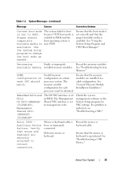
... setup program to UEFI. available memory installed memory modules. The memory module configuration for NIC settings. Check the system management software or the System Setup program for each CPU should match. Mouse or keyboard cable is operational. Reseat the mouse or keyboard cable. See "Using the System Setup Program and UEFI Boot Manager." Ensure that the memory modules are securely attached to correct connectors. Ensure that the proper bootable media is set in BIOS and the compatible boot operating...
... setup program to UEFI. available memory installed memory modules. The memory module configuration for NIC settings. Check the system management software or the System Setup program for each CPU should match. Mouse or keyboard cable is operational. Reseat the mouse or keyboard cable. See "Using the System Setup Program and UEFI Boot Manager." Ensure that the memory modules are securely attached to correct connectors. Ensure that the proper bootable media is set in BIOS and the compatible boot operating...
Hardware Manual
Page 73
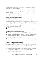
... setup password. When you verify the password, the Setup Password changes to access the setup password window. iDRAC Configuration Utility The iDRAC Configuration Utility is not case-sensitive. If you must enter the correct setup password before modifying most of the System Setup options. Deleting or Changing an Existing Setup Password 1 Enter the System Setup program and select the System Security. 2 Highlight Setup Password, press to Enabled. To erase a character, press or the left-arrow key. Operating With a Setup Password Enabled If Setup Password is Enabled...
... setup password. When you verify the password, the Setup Password changes to access the setup password window. iDRAC Configuration Utility The iDRAC Configuration Utility is not case-sensitive. If you must enter the correct setup password before modifying most of the System Setup options. Deleting or Changing an Existing Setup Password 1 Enter the System Setup program and select the System Security. 2 Highlight Setup Password, press to Enabled. To erase a character, press or the left-arrow key. Operating With a Setup Password Enabled If Setup Password is Enabled...
Hardware Manual
Page 120
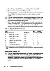
... 3-1 provides a guide for installing expansion cards to ensure proper cooling and mechanical fit. Expansion-Card Installation Order Card Priority Card Type Slot Priority Max Greater Allowed Than 15W? 1 PERC 5/E controller 1,3,4 2 Y 2 PERC 6/E controller 3,4,1 2 Y 3 10 Gb NIC 3,4,1,2 2 Y 4 All other Dell storage cards 3,4,1 2 Y 5 All other expansion cards should only perform troubleshooting and simple repairs as directed by the online or telephone service and support team. Damage due to servicing that the maximum power does...
... 3-1 provides a guide for installing expansion cards to ensure proper cooling and mechanical fit. Expansion-Card Installation Order Card Priority Card Type Slot Priority Max Greater Allowed Than 15W? 1 PERC 5/E controller 1,3,4 2 Y 2 PERC 6/E controller 3,4,1 2 Y 3 10 Gb NIC 3,4,1,2 2 Y 4 All other Dell storage cards 3,4,1 2 Y 5 All other expansion cards should only perform troubleshooting and simple repairs as directed by the online or telephone service and support team. Damage due to servicing that the maximum power does...

Hardware Manual
Page 156
... speed and duplex. If all set to servicing that all network cables are of the proper type and do not exceed the maximum length. See "Installing System Components." • Cooling shroud • Hard drives • SD cards • USB memory key • NIC hardware key • Internal SD Module • Expansion cards and both expansion-card risers • Integrated storage controller • iDRAC6 Enterprise card 156 Troubleshooting Your System See "Integrated Devices Screen...
... speed and duplex. If all set to servicing that all network cables are of the proper type and do not exceed the maximum length. See "Installing System Components." • Cooling shroud • Hard drives • SD cards • USB memory key • NIC hardware key • Internal SD Module • Expansion cards and both expansion-card risers • Integrated storage controller • iDRAC6 Enterprise card 156 Troubleshooting Your System See "Integrated Devices Screen...

Hardware Manual
Page 161
... memory settings match the installed memory but a problem is not operational, turn on the screen or LCD panel. See "Using Dell™ PowerEdge™ Diagnostics." See "Memory Settings Screen." Make any changes to step 14 if an error message appears indicating a fault with all applicable guidelines. 1 If the system is operational, run the appropriate online diagnostic test. See "Installing Memory Modules." 10 Replace the cooling shroud. If diagnostics indicates a fault, follow the corrective actions provided by the diagnostic...
... memory settings match the installed memory but a problem is not operational, turn on the screen or LCD panel. See "Using Dell™ PowerEdge™ Diagnostics." See "Memory Settings Screen." Make any changes to step 14 if an error message appears indicating a fault with all applicable guidelines. 1 If the system is operational, run the appropriate online diagnostic test. See "Installing Memory Modules." 10 Replace the cooling shroud. If diagnostics indicates a fault, follow the corrective actions provided by the diagnostic...
Hardware Manual
Page 162
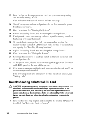
... Reconnect the system to servicing that appears on the screen or the LCD panel on the front of the same type and capacity. 13 Enter the System Setup program and check the system memory setting. See "Memory Settings Screen." See "Opening the System." 16 Remove the cooling shroud. Troubleshooting an Internal SD Card CAUTION: Many repairs may only be done by Dell is enabled. See "Integrated Devices Screen." 162 Troubleshooting Your System
... Reconnect the system to servicing that appears on the screen or the LCD panel on the front of the same type and capacity. 13 Enter the System Setup program and check the system memory setting. See "Memory Settings Screen." See "Opening the System." 16 Remove the cooling shroud. Troubleshooting an Internal SD Card CAUTION: Many repairs may only be done by Dell is enabled. See "Integrated Devices Screen." 162 Troubleshooting Your System
Hardware Manual
Page 164
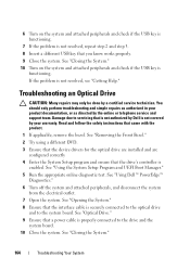
... System." 164 Troubleshooting Your System See "Using the System Setup Program and UEFI Boot Manager." 5 Run the appropriate online diagnostic test. Read and follow the safety instructions that a power cable is properly connected to the drive and the system board. 10 Close the system. See "Removing the Front Bezel." 2 Try using a different DVD. 3 Ensure that the device drivers for the optical drive are installed and are configured correctly 4 Enter the System Setup program and ensure...
... System." 164 Troubleshooting Your System See "Using the System Setup Program and UEFI Boot Manager." 5 Run the appropriate online diagnostic test. Read and follow the safety instructions that a power cable is properly connected to the drive and the system board. 10 Close the system. See "Removing the Front Bezel." 2 Try using a different DVD. 3 Ensure that the device drivers for the optical drive are installed and are configured correctly 4 Enter the System Setup program and ensure...

Hardware Manual
Page 166
... for the tape drive for additional troubleshooting instructions. See "Removing the Front Bezel." 3 If your hard drives are configured in your warranty. See "Using Dell™ PowerEdge™ Diagnostics." See the documentation supplied with the product. b For SATA tape devices, reseat the interface cable to the electrical outlet, and turn on the results of the diagnostics test, proceed as directed by your product documentation, or as needed through the...
... for the tape drive for additional troubleshooting instructions. See "Removing the Front Bezel." 3 If your hard drives are configured in your warranty. See "Using Dell™ PowerEdge™ Diagnostics." See the documentation supplied with the product. b For SATA tape devices, reseat the interface cable to the electrical outlet, and turn on the results of the diagnostics test, proceed as directed by your product documentation, or as needed through the...

Hardware Manual
Page 179
If the configuration settings become corrupted to the point where the system will not boot, install the jumper and boot the system. Remove the jumper before restoring the configuration information. Jumpers and Connectors 179 Jumper Setting Description Pins 1 and 3 The configuration settings are cleared at the next system boot.
If the configuration settings become corrupted to the point where the system will not boot, install the jumper and boot the system. Remove the jumper before restoring the configuration information. Jumpers and Connectors 179 Jumper Setting Description Pins 1 and 3 The configuration settings are cleared at the next system boot.
Hardware Manual
Page 197
... system board and storage devices. SD card - SDDC - Allows hard drives to report errors and failures to remotely monitor and manage workstations. Used to describe a system that has two or more disks in an array, but only uses a portion of your system's hardware and customize the system's operation by a "stripe" is stored in NVRAM, any settings remain in effect until you call Dell for technical support. striping - See RAM. Self-Monitoring...
... system board and storage devices. SD card - SDDC - Allows hard drives to report errors and failures to remotely monitor and manage workstations. Used to describe a system that has two or more disks in an array, but only uses a portion of your system's hardware and customize the system's operation by a "stripe" is stored in NVRAM, any settings remain in effect until you call Dell for technical support. striping - See RAM. Self-Monitoring...

Hardware Manual
Page 198
...) DDR3 memory module. Unified Extensible Firmware Interface. Universal Serial Bus. USB devices can display (with the monitor) your system's video capabilities. A program used to connect to enable or disable the termination on these devices by changing jumper or switch settings on the devices or by the number of pixels across by changing settings in the cable. VDC - The amount of video memory installed primarily influences the number of an electrical failure. Transmission Control Protocol/Internet Protocol. UDIMM - USB memory key - See memory key. Volt...
...) DDR3 memory module. Unified Extensible Firmware Interface. Universal Serial Bus. USB devices can display (with the monitor) your system's video capabilities. A program used to connect to enable or disable the termination on these devices by changing jumper or switch settings on the devices or by the number of pixels across by changing settings in the cable. VDC - The amount of video memory installed primarily influences the number of an electrical failure. Transmission Control Protocol/Internet Protocol. UDIMM - USB memory key - See memory key. Volt...
Hardware Manual
Page 201
battery (RAID) installing, 116 removing, 116 battery (system) replacing, 141 troubleshooting, 158 BIOS boot mode, 55 blank hard drive, 81 power supply, 88 boot mode, 55 C cable retention bracket installing, 119 removing, 118 cable routing, 118 cabling cable routing, 118 optical drive, 103 storage controller (2.5-in HDD chassis), 114 storage controller (four 3.5-in HDD chassis), 115 storage controller (six 3.5-in HDD chassis), 116 connectors expansion-card riser 1, 185 expansion-card riser 2, 186-187 NIC, 20 SAS backplane board, 182 serial, 20 system board, 180 USB, 12 video, 12 contacting...
battery (RAID) installing, 116 removing, 116 battery (system) replacing, 141 troubleshooting, 158 BIOS boot mode, 55 blank hard drive, 81 power supply, 88 boot mode, 55 C cable retention bracket installing, 119 removing, 118 cable routing, 118 cabling cable routing, 118 optical drive, 103 storage controller (2.5-in HDD chassis), 114 storage controller (four 3.5-in HDD chassis), 115 storage controller (six 3.5-in HDD chassis), 116 connectors expansion-card riser 1, 185 expansion-card riser 2, 186-187 NIC, 20 SAS backplane board, 182 serial, 20 system board, 180 USB, 12 video, 12 contacting...

Hardware Manual
Page 206
... Dell, 189 system board connectors, 180 installing, 150 jumpers, 177 removing, 148 system cooling troubleshooting, 159 system features accessing, 11 system messages, 37 system password, 70 system setup program boot settings, 61 embedded server management options, 64 integrated devices options, 62 keystroke to enter, 56 main screen, 57 memory settings, 59 PCI IRQ assignments, 63 power management options, 65 processor settings, 60 SATA settings, 60 serial communications options, 63 system security options, 66 system startup failure, 153 206 Index 2.5-inch hard drives, 182 3.5-inch hard drives...
... Dell, 189 system board connectors, 180 installing, 150 jumpers, 177 removing, 148 system cooling troubleshooting, 159 system features accessing, 11 system messages, 37 system password, 70 system setup program boot settings, 61 embedded server management options, 64 integrated devices options, 62 keystroke to enter, 56 main screen, 57 memory settings, 59 PCI IRQ assignments, 63 power management options, 65 processor settings, 60 SATA settings, 60 serial communications options, 63 system security options, 66 system startup failure, 153 206 Index 2.5-inch hard drives, 182 3.5-inch hard drives...

Hardware Manual
Page 207
..., 66 troubleshooting cooling fans, 160 damaged system, 157 external connections, 153 hard drive, 166 internal USB memory key, 163 keyboard, 154 memory, 160 NIC, 155 optical drive, 164 PCIe expansion cards, 168 power supplies, 158 processor(s), 170 SD card, 162 storage controller, 167 system battery, 158 system cooling, 159 system startup failure, 153 tape backup unit, 165 video, 154 wet system, 156 U UEFI Boot Manager entering, 68 main screen, 69 System Utilities screen, 69 UEFI Boot Settings screen, 69 UEFI boot mode, 55 upgrades processor, 137 USB back-panel connectors...
..., 66 troubleshooting cooling fans, 160 damaged system, 157 external connections, 153 hard drive, 166 internal USB memory key, 163 keyboard, 154 memory, 160 NIC, 155 optical drive, 164 PCIe expansion cards, 168 power supplies, 158 processor(s), 170 SD card, 162 storage controller, 167 system battery, 158 system cooling, 159 system startup failure, 153 tape backup unit, 165 video, 154 wet system, 156 U UEFI Boot Manager entering, 68 main screen, 69 System Utilities screen, 69 UEFI Boot Settings screen, 69 UEFI boot mode, 55 upgrades processor, 137 USB back-panel connectors...
Technical Guide
Page 21
... switches on the control panel or set up a system password. 4.12 USB Key The port on the control panel is for an optional USB key and is mounted on the planar to provide backup power for binding. 4.11.5 Power Off Security The control panel is designed so the power switch cannot be used to detect chassis intrusion. PowerEdge R710 Technical Guide 21 When the cover is opened . 4.11.7 Secure Mode BIOS has the ability to enter a secure boot mode through a BIOS option and uses...
... switches on the control panel or set up a system password. 4.12 USB Key The port on the control panel is for an optional USB key and is mounted on the planar to provide backup power for binding. 4.11.5 Power Off Security The control panel is designed so the power switch cannot be used to detect chassis intrusion. PowerEdge R710 Technical Guide 21 When the cover is opened . 4.11.7 Secure Mode BIOS has the ability to enter a secure boot mode through a BIOS option and uses...
Technical Guide
Page 22
... Power Controller (BIOS-based CPU P-state manager) Ability to power down or throttle memory Ability to disable a processor core Ability to turn off embedded NICs or PCIe lanes when not being used Option to run PCIe at Gen1 speeds instead of Gen2 5.2 Main Power Supply The base redundant R710 system consists of two hot-plug 570W Energy Smart (energy efficient) power supplies in a 1+1 configuration. Additionally, the power supply firmware can...
... Power Controller (BIOS-based CPU P-state manager) Ability to power down or throttle memory Ability to disable a processor core Ability to turn off embedded NICs or PCIe lanes when not being used Option to run PCIe at Gen1 speeds instead of Gen2 5.2 Main Power Supply The base redundant R710 system consists of two hot-plug 570W Energy Smart (energy efficient) power supplies in a 1+1 configuration. Additionally, the power supply firmware can...

Technical Guide
Page 38
... (R710 operates this controller at Gen1 speed) Integrated MAC and PHY 3072x18 Byte context memory 64 KB receive buffer TOE (TCP Offload Engine) iSCSI controller (enabled through an optional hardware key) RDMA controller (RNIC) (enabled through optional hardware key) NC-SI (Network Controller-Sideband Interface) connection for manageability Wake-On-LAN (WOL) PXE 2.0 remote boot iSCSI boot IPv4 and IPv6 support Bare metal deployment support PowerEdge R710 Technical Guide...
... (R710 operates this controller at Gen1 speed) Integrated MAC and PHY 3072x18 Byte context memory 64 KB receive buffer TOE (TCP Offload Engine) iSCSI controller (enabled through an optional hardware key) RDMA controller (RNIC) (enabled through optional hardware key) NC-SI (Network Controller-Sideband Interface) connection for manageability Wake-On-LAN (WOL) PXE 2.0 remote boot iSCSI boot IPv4 and IPv6 support Bare metal deployment support PowerEdge R710 Technical Guide...
Technical Guide
Page 41
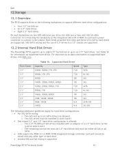
... drives installed with an adapter in a 3.5‖ hard-drive carrier in a 3.5" chassis are supported. 12.2 Internal Hard Disk Drives The PowerEdge R710 supports up to eight 2.5‖ hard drives or up to six 3.5‖ hard drives. For the most up-to-date information on supported hard drives. SAS/SATA mixing and the use of 2.5" drives in drive slots 0 and 1 o The remaining hard drives must be 3.5‖ hard drives and must be mixed with one or two mini-SAS x4 cable connectors...
... drives installed with an adapter in a 3.5‖ hard-drive carrier in a 3.5" chassis are supported. 12.2 Internal Hard Disk Drives The PowerEdge R710 supports up to eight 2.5‖ hard drives or up to six 3.5‖ hard drives. For the most up-to-date information on supported hard drives. SAS/SATA mixing and the use of 2.5" drives in drive slots 0 and 1 o The remaining hard drives must be 3.5‖ hard drives and must be mixed with one or two mini-SAS x4 cable connectors...
Technical Guide
Page 55
...PowerEdge R710 Technical Guide 55 Unified Server Configurator Features and Description Feature Faster O/S Installation Faster System Updates Update Rollback More Comprehensive Diagnostics Simplified Hardware Configuration Description Drivers and the installation utility are embedded on system Detects RAID controller and allows user to previous ―known good state‖ for all updatable components Diagnostic utilities are there‖ presence and control. Also provides configuration for iDRAC, BIOS, and NIC/LOM. 16.5 Integrated Dell Remote Access Controller The integrated Dell...
...PowerEdge R710 Technical Guide 55 Unified Server Configurator Features and Description Feature Faster O/S Installation Faster System Updates Update Rollback More Comprehensive Diagnostics Simplified Hardware Configuration Description Drivers and the installation utility are embedded on system Detects RAID controller and allows user to previous ―known good state‖ for all updatable components Diagnostic utilities are there‖ presence and control. Also provides configuration for iDRAC, BIOS, and NIC/LOM. 16.5 Integrated Dell Remote Access Controller The integrated Dell...


