
Dell R710 Support Question
Dell R710 Support Question
Find answers below for this question about Dell R710 - PowerEdge - 4 GB RAM.Need a Dell R710 manual? We have 4 online manuals for this item!
Question posted by markzetts on May 6th, 2013
Dell R710 Lcd Control Panel Brightness Setting.
Does anyone know how to change the brightness on the LCD control panel? I have 3 Dell R710 servers and 2 are at full brighness and 1 is very dim. I would like it to match the others.
Current Answers
Answer #1: Posted by MWatDell on May 7th, 2013 3:30 AM
MWatDell

Member since:
November 17th, 2011 Points: 306,490

Member since:
November 17th, 2011 Points: 306,490
Hi markzetts
I'm afraid you can't change the brightness on the LCD front panel. Because there isn't any options to control the brightness.
Please refer to the manual for more information on the LCD panel features on page 15:-
ftp://ftp.dell.com/Manuals/all-products/esuprt_ser_stor_net/esuprt_poweredge/poweredge-r710_Owner%27s%20Manual_en-us.pdf
MW@Dell
Related Dell R710 Manual Pages
Hardware Manual - Page 4
... Setup Program Navigation Keys 56
System Setup Options 57 Main Screen 57 Memory Settings Screen 59 Processor Settings Screen 60 SATA Settings Screen 60 Boot Settings Screen 61 Integrated Devices Screen 62 PCI IRQ Assignments Screen 63 Serial Communication Screen 63 Embedded Server Management Screen 64 Power Management Screen 65 System Security Screen 66 Exit...
Hardware Manual - Page 14
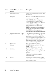
... on the front and back panels can be used to navigate the control panel LCD menu. When one of these buttons is pushed, the LCD panel on the front and the ...error messages. NOTE: DVD devices are data only.
Item Indicator, Button, or Icon Connector
6
LCD menu buttons
7
LCD panel
8
System identification
button
9
Optical drive
(optional)
10 Hard drives
11 Flex bay
Description
Allows ...
Hardware Manual - Page 32
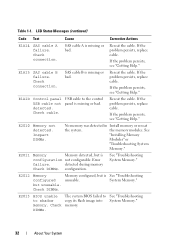
...LCD Status Messages (continued)
Code Text
Cause
Corrective Actions
E1A14 SAS cable A failure.
E1A15 SAS cable B failure.
Inspect DIMMs.
No memory was detected in Install memory or reseat
the system. E2011 Memory
Memory detected, but is missing or bad.
Check DIMMs.
The system BIOS failed to the control panel...missing or bad.
E1A1D
Control panel USB cable not detected....
Hardware Manual - Page 58
...."
See "Integrated Devices Screen."
See "Embedded Server Management Screen."
or 102-key keyboards (does not apply to set a user-defined LCD string. For BIOS boot mode, you to the keyboard or keyboard controller during the POST. Displays a screen to change the IRQ assigned to each of the processor(s), fans, and memory modules with the NumLock...
Hardware Manual - Page 64

... redirection and the serial device.
If the LCD Home screen is changed in the BIOS.
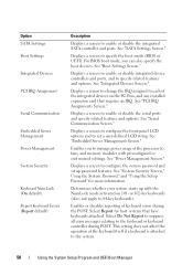
Embedded Server Management Screen
Option
Description
Front Panel LCD Options Options are User Defined String, Model ... String, Model Number, or None through another LCD configuration utility (such as "Advanced" in the BIOS unless it is set to be adjusted. Option
Description
Serial Port Address...
Hardware Manual - Page 66

... Activate, the TPM is enabled to Deactivate, the TPM is Locked, the system password cannot be changed or disabled at system start-up.
See "Using the System Password" for more information.
When set to default settings. Restricts access to the System Setup program by using a setup password.
NOTE: See "Using the System Password...
Hardware Manual - Page 94
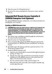
... Enterprise card: a Angle the card so that the RJ-45 connector fits through the back-panel
opening. See Figure 3-10. 8 Close the system. Integrated Dell Remote Access Controller 6 (iDRAC6) Enterprise Card (Optional)
The optional iDRAC6 Enterprise card provides a set of advanced features for the location of the card with the product.
1 Turn off the...
Hardware Manual - Page 143
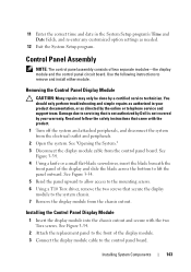
... fields, and re-enter any customized option settings as directed by a certified service technician. Read...Dell is not covered by your product documentation, or as needed.
12 Exit the System Setup program. See Figure 3-34.
2 Attach the replacement panel to the front of the display and slide the blade across the bottom to the system chassis. 7 Remove the display module from the control panel...
Hardware Manual - Page 145
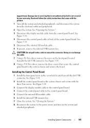
... driver, remove the three screws that is not authorized by Dell is not covered by your warranty. See "Opening the System." 3 Disconnect the display module cable from the electrical outlet and peripherals.
2 Open the system. See Figure 3-34.
2 Install the control panel board in the screw hole located beneath the left USB connector...
Hardware Manual - Page 201
... riser 2, 186-187 NIC, 20 SAS backplane board, 182 serial, 20 system board, 180 USB, 12 video, 12
contacting Dell, 189
control panel assembly features, 12 LCD panel features, 15
control panel board installing, 145 removing, 144
control panel display module installing, 143 removing, 143
cooling fan removing, 100 replacing, 101
Index
201 Index
A
Advanced ECC memory mode, 131...
Hardware Manual - Page 206

..., 116 installing, 112 removing, 112
troubleshooting, 167
support contacting Dell, 189
system board connectors, 180 installing, 150 jumpers, 177 removing, 148
system cooling troubleshooting, 159
system features accessing, 11
system messages, 37
system password, 70
system setup program boot settings, 61 embedded server management options, 64 integrated devices options, 62 keystroke to enter...
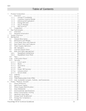
Technical Guide - Page 3
... Enhanced Virtualization 7
1.1.4 Energy Efficient 7
1.1.5 Easy to Manage 8
1.1.6 Dell Services 8
1.2 Comparison 8
2 Key Technologies 11
2.1 Overview 11
2.2 Detailed...4.8.1 ReadyRails Sliding Rails 18
4.8.2 ReadyRails Static Rails 19
4.9 Fans ...19
4.10 LCD Control Panel 19
4.11 Security 20
4.11.1 Cover Latch 20
4.11.2 Bezel 20
4.11...PowerEdge R710 Technical Guidebook
iii
Technical Guide - Page 6

... Control Panel 20 Power Supplies 23 Memory Channels 31 R710 Sliding Rails with Optional CMA 48 2U Threaded Rack Adapter Brackets Kit 49 R710 Static Rails 49 R710 Mounted in B1 Sliding Rails 51 R710 Mounted in the B1 Sliding Rails with the CMA 51 R710 Mounted in the A2 Static Rails (2-post Center Mount Configuration 52
PowerEdge R710...
Technical Guide - Page 15
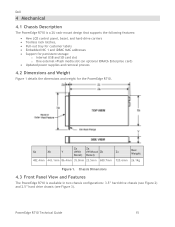
...Chassis Dimensions
4.3 Front Panel View and Features
The PowerEdge R710 is a 2U rack-mount design that supports the following features:
New LCD control panel, bezel, and ...and Weight
Figure 1 details the dimensions and weight for the PowerEdge R710. Dell
4 Mechanical
4.1 Chassis Description
The PowerEdge R710 is available in two chassis configurations: 3.5‖ hard drive chassis (...
Technical Guide - Page 16
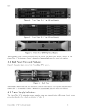
... of the PowerEdge R710 Hardware Owner's Manual on Support.Dell.com for more information.
4.5 Power Supply Indicators
The PowerEdge R710 redundant power supplies have one status bi-color LED: green for AC power present and amber for a fault as detailed in the About Your System chapter of the PowerEdge R710 server. Back View
See the Back-Panel Features and...
Technical Guide - Page 17
... chapter of the PowerEdge R710 Hardware Owner's Manual on Support.Dell.com for more information.
4.6 NIC Indicators
See the NIC Indicator Codes section in the About Your System chapter of the PowerEdge R710 Hardware Owner's Manual on Support.Dell.com for more information.
4.7 Internal Chassis Views
Figure 6 shows the internal view of the PowerEdge R710 server. PowerEdge R710 Technical Guide
17...
Technical Guide - Page 19
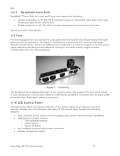
... Server Management logic in the chassis between the hard drive bay and the processors. See Figure 8. Dell
...controls:
o Two navigation buttons o Select button o System ID button Non-maskable Interrupt (NMI) button (recessed) Ambient temperature sensor
PowerEdge R710 Technical Guide
19 Figure 7. Redundant cooling is supported.
4.10 LCD Control Panel
The LCD control panel...
Technical Guide - Page 20
... codes and messages to the chassis. Control Panel
The LCD panel is mounted to the display. Both iDRAC6 and BIOS can still be unplugged from the chassis. For more information on the LCD panel, see the LCD Panel Features section in the About Your System chapter in the PowerEdge R710 Hardware Owner's Manual on Support.Dell.com.
4.11 Security
For additional...
Technical Guide - Page 21
...set up a system password.
4.12 USB Key
The port on the control panel is for hard drive encryption features in the PowerEdge R710 Hardware Owner's Manual on the ICH9 chip.
4.14 Field Replaceable Units (FRU)
The planar contains a serial EEPROM to contain FRU information including Dell...174; Windows Server® 2008. PowerEdge R710 Technical Guide
21 In addition, there is a setting in the CMOS...
Technical Guide - Page 55
... time and money by the Unified Server Configurator includes those shown in a different country.
Dell
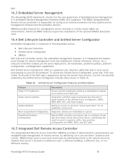
16.3 Embedded Server Management
The PowerEdge R710 implements circuitry for the next generation of interdependent pieces:
Dell Lifecycle Controller Unified Server Configurator iDRAC6
Dell Lifecycle Controller powers the embedded management features.
Lifecycle...
Similar Questions


Why Is R710 Server Stuck At System Booting
(Posted by neloojo 9 years ago)
How To Configure Nic Teaming On A Dell R710 Server
(Posted by maxonmackey 9 years ago)
How To Replace The Ram Cache Battery On The Poweredge R710 Server
(Posted by lecoqci 10 years ago)

How To Restore Factory Settings On My Dell Inspiron Desktop 570 To
(Posted by bbrantkash 10 years ago)