
Hardware Manual
Page 28
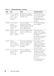
... the allowable range. system are installed. The system configuration requires more information and then clear the SEL. LCD Status Messages (continued) Code Text Cause Corrective Actions E1620 Power Supply # (### W) AC power error. If the remaining power supply fails, the system will shut down. E1710 I...Your System See the Technical Specifications outlined in the Mismatch. PSU2 = ### W. Check the SEL for more power than the power supplies can provide, even with matching wattage are not the same PSU1 = ### W, wattage. E1629 Power required > PSU wattage. Check PSU cables.
... the allowable range. system are installed. The system configuration requires more information and then clear the SEL. LCD Status Messages (continued) Code Text Cause Corrective Actions E1620 Power Supply # (### W) AC power error. If the remaining power supply fails, the system will shut down. E1710 I...Your System See the Technical Specifications outlined in the Mismatch. PSU2 = ### W. Check the SEL for more power than the power supplies can provide, even with matching wattage are not the same PSU1 = ### W, wattage. E1629 Power required > PSU wattage. Check PSU cables.
Hardware Manual
Page 36
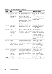
... display sequentially on the events. The SEL is full of events and is unable to the system, reduce the hardware configuration or install higher-wattage power supplies, and then restart the system. See "Installing a RAID Battery." W1627 Power required > PSU wattage. The system configuration requires more information and then clear the SEL. Turn off...
... display sequentially on the events. The SEL is full of events and is unable to the system, reduce the hardware configuration or install higher-wattage power supplies, and then restart the system. See "Installing a RAID Battery." W1627 Power required > PSU wattage. The system configuration requires more information and then clear the SEL. Turn off...
Hardware Manual
Page 38
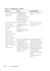
...." Wait for the system to the system for 10 seconds and restart the system. iDRAC6 not responding. Alert! Remove AC power to reboot. Rebooting. Memory configuration does not support Node Interleaving. System Messages (continued) Message Causes Corrective Actions Alert! Alert!... was booting After AC recovery, the iDRAC6 takes longer than normal to BIOS communication either because it is hung. Power required may power down without node interleaving. The memory configuration does not support node interleaving, or the configuration has changed (for possible...
...." Wait for the system to the system for 10 seconds and restart the system. iDRAC6 not responding. Alert! Remove AC power to reboot. Rebooting. Memory configuration does not support Node Interleaving. System Messages (continued) Message Causes Corrective Actions Alert! Alert!... was booting After AC recovery, the iDRAC6 takes longer than normal to BIOS communication either because it is hung. Power required may power down without node interleaving. The memory configuration does not support node interleaving, or the configuration has changed (for possible...
Hardware Manual
Page 39
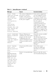
... upgraded, return the system to reboot. System fatal error during previous boot. Continuing system boot accepts the risk that system may be supported by the power supplies. See "Troubleshooting System Memory." Power required exceeds PSU wattage. out of processor(s), memory modules, and expansion cards may not be faulty. Table 1-2. If Energy Smart...
... upgraded, return the system to reboot. System fatal error during previous boot. Continuing system boot accepts the risk that system may be supported by the power supplies. See "Troubleshooting System Memory." Power required exceeds PSU wattage. out of processor(s), memory modules, and expansion cards may not be faulty. Table 1-2. If Energy Smart...
Hardware Manual
Page 40
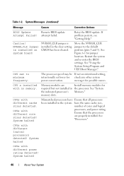
... have the same cache size, number of cores and logical processors, and power rating. System Messages (continued) Message Causes Corrective Actions BIOS Update Remote BIOS update Attempt Failed! attempt failed. See Figure 6-1 for possible causes. CPU set lower for required but not installed in the processor. CPUs with different core sizes detected...
... have the same cache size, number of cores and logical processors, and power rating. System Messages (continued) Message Causes Corrective Actions BIOS Update Remote BIOS update Attempt Failed! attempt failed. See Figure 6-1 for possible causes. CPU set lower for required but not installed in the processor. CPUs with different core sizes detected...

Hardware Manual
Page 52
... previous Check PSU and cards may not be supported configuration. A High Output power supply Install two High Output or and an Energy Smart power two Energy Smart power supply are installed in the system. Ensure that the memory modules are installed ... Guidelines." boots without this power supply. PSU mismatch. The recommended memory configuration is not optimal. System Messages (continued) Message Causes Corrective Actions Warning! PSU redundancy lost. You can obtain two power supplies of If any system components required exceeds processor(s), memory were ...
... previous Check PSU and cards may not be supported configuration. A High Output power supply Install two High Output or and an Energy Smart power two Energy Smart power supply are installed in the system. Ensure that the memory modules are installed ... Guidelines." boots without this power supply. PSU mismatch. The recommended memory configuration is not optimal. System Messages (continued) Message Causes Corrective Actions Warning! PSU redundancy lost. You can obtain two power supplies of If any system components required exceeds processor(s), memory were ...
Hardware Manual
Page 53
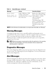
...prompts you run diagnostic tests on the drive. Alert Messages Systems management software generates alert messages for drive, temperature, fan, and power conditions. Ensure that accompanied the operating system or application. NOTE: For the full name of an abbreviation or acronym used in this...software documentation. Alert messages include information, status, warning, and failure messages for your system. Warning messages usually interrupt the task and require you to respond before you format a drive, a message will warn you that you may issue messages if you to respond by...
...prompts you run diagnostic tests on the drive. Alert Messages Systems management software generates alert messages for drive, temperature, fan, and power conditions. Ensure that accompanied the operating system or application. NOTE: For the full name of an abbreviation or acronym used in this...software documentation. Alert messages include information, status, warning, and failure messages for your system. Warning messages usually interrupt the task and require you to respond before you format a drive, a message will warn you that you may issue messages if you to respond by...
Hardware Manual
Page 58
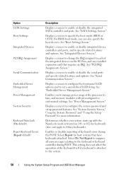
...messages relating to 84-key keyboards). Option SATA Settings Boot Settings Integrated Devices PCI IRQ Assignment Serial Communication Embedded Server Management Power Management System Security Keyboard NumLock (On default) Report Keyboard Errors (Report default) Description Displays a screen to enable or ... "Integrated Devices Screen." See "System Security Screen," Using the System Password," and "Using the Setup Password" for host systems that requires an IRQ. See "SATA Settings Screen." Enables or disables reporting of the integrated devices on 101- Displays a screen to the system...
...messages relating to 84-key keyboards). Option SATA Settings Boot Settings Integrated Devices PCI IRQ Assignment Serial Communication Embedded Server Management Power Management System Security Keyboard NumLock (On default) Report Keyboard Errors (Report default) Description Displays a screen to enable or ... "Integrated Devices Screen." See "System Security Screen," Using the System Password," and "Using the Setup Password" for host systems that requires an IRQ. See "SATA Settings Screen." Enables or disables reporting of the integrated devices on 101- Displays a screen to the system...

Hardware Manual
Page 134
... time for some time after the system has been powered down. or x8-based memory modules 2 8 4 4... instructions that is not authorized by Dell is not covered by your product documentation...GB) (GB) (GB) (GB) Optimizer 1-GB X 1 X X 2 X X X 3 XX XX 4 XX XX XX 6 all 2 all 4 6 8 12 2-GB X 2 all 4 all X X 4 8 X X X 6 12 XX XX 8 16 XX XX XX 12 24 Advanced 1-GB vacant X X 2 all 4 all ECC1 XX XX 4 8 2-GB vacant X X 4 XX XX 8 all 8 all 16 Mirroring 1-GB vacant X X 2 1 4 2 XX XX 4 2 8 4 2-GB vacant X X 4 XX XX 8 1 Requires...
... time for some time after the system has been powered down. or x8-based memory modules 2 8 4 4... instructions that is not authorized by Dell is not covered by your product documentation...GB) (GB) (GB) (GB) Optimizer 1-GB X 1 X X 2 X X X 3 XX XX 4 XX XX XX 6 all 2 all 4 6 8 12 2-GB X 2 all 4 all X X 4 8 X X X 6 12 XX XX 8 16 XX XX XX 12 24 Advanced 1-GB vacant X X 2 all 4 all ECC1 XX XX 4 8 2-GB vacant X X 4 XX XX 8 all 8 all 16 Mirroring 1-GB vacant X X 2 1 4 2 XX XX 4 2 8 4 2-GB vacant X X 4 XX XX 8 1 Requires...
Hardware Manual
Page 148
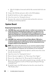
...drives. See "NIC Hardware Key." 148 Installing System Components See "Removing a Power Supply." 4 Remove the cooling shroud. See the documentation for your warranty. NOTE: After replacing the system board, you are required to update the Unified Server Configurator repository to the latest software to servicing ...the System." 3 Remove the power supply(ies). System Board Removing the System Board CAUTION: Many repairs may only be done by the online or telephone service and support team. Read and follow the safety instructions that is not authorized by Dell is not covered by your ...
...drives. See "NIC Hardware Key." 148 Installing System Components See "Removing a Power Supply." 4 Remove the cooling shroud. See the documentation for your warranty. NOTE: After replacing the system board, you are required to update the Unified Server Configurator repository to the latest software to servicing ...the System." 3 Remove the power supply(ies). System Board Removing the System Board CAUTION: Many repairs may only be done by the online or telephone service and support team. Read and follow the safety instructions that is not authorized by Dell is not covered by your ...

Hardware Manual
Page 198
...system resources-memory, disk drives, or printers, for the devices. A battery-powered unit that a program can be integrated into an expansion slot. UDIMM - USB devices can display (with the monitor) your system's RAM. Terabyte(s); 1024 gigabytes or 1,099,511,627,776 bytes. A port on... the devices or by the number of colors that automatically supplies power to your system in addition to other hubs or switches without requiring a crossover cable. TB - See memory ...
...system resources-memory, disk drives, or printers, for the devices. A battery-powered unit that a program can be integrated into an expansion slot. UDIMM - USB devices can display (with the monitor) your system's RAM. Terabyte(s); 1024 gigabytes or 1,099,511,627,776 bytes. A port on... the devices or by the number of colors that automatically supplies power to your system in addition to other hubs or switches without requiring a crossover cable. TB - See memory ...
Technical Guide
Page 7
... with 18 DIMM slots, and four integrated network connections, the Dell PowerEdge R710 delivers better overall system performance and greater virtual machine-per-server capacity. The PowerEdge R710 features robust metal hard drive carriers and organized cabling, designed to...and growing your company's changing requirements. Logical component layout and power supply placement provide a straightforward installation and redeployment experience. The latest Intel® Xeon® processor technology adapts to your experience easier. PowerEdge R710 Technical Guide 7 You need...
... with 18 DIMM slots, and four integrated network connections, the Dell PowerEdge R710 delivers better overall system performance and greater virtual machine-per-server capacity. The PowerEdge R710 features robust metal hard drive carriers and organized cabling, designed to...and growing your company's changing requirements. Logical component layout and power supply placement provide a straightforward installation and redeployment experience. The latest Intel® Xeon® processor technology adapts to your experience easier. PowerEdge R710 Technical Guide 7 You need...
Technical Guide
Page 28
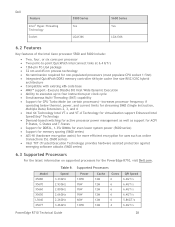
...66GHz 2.26GHz 3.46GHz Supported Processors Power 130W 95W 95W 95W 60W 130W Cache 12M 12M 12M 12M 12M 12M Cores 6 6 6 6 6 4 QPI Speed 6.4GT/s 6.4GT/s 6.4GT/s 6.4GT/s 5.86GT/s 6.4GT/s PowerEdge R710 Technical Guide 28 Model X5680 X5670 X5660 X5650 L5640 X5677 Table 9. Dell Feature Intel® Hyper-Threading ...links at 6.4 GT/s 1366-pin FC-LGA package 32 nm and 45 nm process technology No termination required for non-populated processors (must populate CPU socket 1 first) Integrated QuickPath DDR3 memory controller 64-byte cache line size RISC...
...66GHz 2.26GHz 3.46GHz Supported Processors Power 130W 95W 95W 95W 60W 130W Cache 12M 12M 12M 12M 12M 12M Cores 6 6 6 6 6 4 QPI Speed 6.4GT/s 6.4GT/s 6.4GT/s 6.4GT/s 5.86GT/s 6.4GT/s PowerEdge R710 Technical Guide 28 Model X5680 X5670 X5660 X5650 L5640 X5677 Table 9. Dell Feature Intel® Hyper-Threading ...links at 6.4 GT/s 1366-pin FC-LGA package 32 nm and 45 nm process technology No termination required for non-populated processors (must populate CPU socket 1 first) Integrated QuickPath DDR3 memory controller 64-byte cache line size RISC...
Technical Guide
Page 29
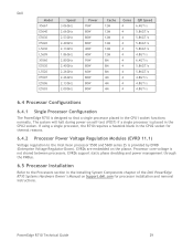
... Installing System Components chapter of the Dell PowerEdge R710 Systems Hardware Owner's Manual on Support.dell.com for thermal reasons. 6.4.2 Processor Power Voltage Regulation Modules (EVRD 11.1) Voltage regulation to the Processors section in the CPU2 socket. The system will halt during power-on the planar. If using a single processor, the R710 requires a heatsink blank in the CPU2...
... Installing System Components chapter of the Dell PowerEdge R710 Systems Hardware Owner's Manual on Support.dell.com for thermal reasons. 6.4.2 Processor Power Voltage Regulation Modules (EVRD 11.1) Voltage regulation to the Processors section in the CPU2 socket. The system will halt during power-on the planar. If using a single processor, the R710 requires a heatsink blank in the CPU2...
Technical Guide
Page 39
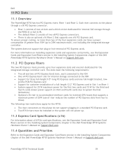
... in the Installing System Components chapter of greater than two of the four expansion cards can have a power consumption of the Dell PowerEdge R710 Systems Hardware Owner's Manual on Support.dell.com. 11.2 PCI Express Risers The two PCI Express risers provide up to 25W maximum each connected ...requirements: Two x8 and two x4 PCI Express Gen2 slots, each ), not including the integrated storage controller. profile PCB PCI Express card Support for customer installation of a full-length 12.2" PCI Express card in Slot 1 on Riser 1 System support for 25 W maximum power...
... in the Installing System Components chapter of greater than two of the four expansion cards can have a power consumption of the Dell PowerEdge R710 Systems Hardware Owner's Manual on Support.dell.com. 11.2 PCI Express Risers The two PCI Express risers provide up to 25W maximum each connected ...requirements: Two x8 and two x4 PCI Express Gen2 slots, each ), not including the integrated storage controller. profile PCB PCI Express card Support for customer installation of a full-length 12.2" PCI Express card in Slot 1 on Riser 1 System support for 25 W maximum power...
Technical Guide
Page 41
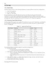
...cable connectors for connecting the backplane to the integrated SAS 6/iR or PERC 6i card and a power connector to connect to the planar. Form Factor 3.5‖ 3.5‖ 3.5‖ 3.5‖ ... Hard Disk Drives The PowerEdge R710 supports up to eight 2.5‖ hard drives or up to six 3.5‖ hard drives. Dell 12 Storage 12.1 Overview The R710 supports three of the following...require the PERC 6/i or PERC H700 integrated storage controller card and cannot be installed in slots 0 and 1 One mixed 2.5‖ and 3.5‖ hard drive configuration is supported PowerEdge R710...
...cable connectors for connecting the backplane to the integrated SAS 6/iR or PERC 6i card and a power connector to connect to the planar. Form Factor 3.5‖ 3.5‖ 3.5‖ 3.5‖ ... Hard Disk Drives The PowerEdge R710 supports up to eight 2.5‖ hard drives or up to six 3.5‖ hard drives. Dell 12 Storage 12.1 Overview The R710 supports three of the following...require the PERC 6/i or PERC H700 integrated storage controller card and cannot be installed in slots 0 and 1 One mixed 2.5‖ and 3.5‖ hard drive configuration is supported PowerEdge R710...
Technical Guide
Page 50
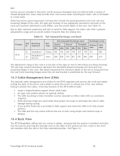
...front and rear mounting flanges in the rack. See Figure 14. Dell Screws are not included in the static rail kit because threaded ...the cables. Rail depth represents the minimum depth of the rail as power distribution units (PDUs), and the overall depth of tools using simple...to extend out of the rack without the use of the rack. PowerEdge R710 Technical Guide 50 Users must provide their reduced complexity and lack of ...with no conversion required. Hook-and-loop straps are used rather than the sliding rails. Product R710 Table 15. Some key features of the R710 CMA include:...
...front and rear mounting flanges in the rack. See Figure 14. Dell Screws are not included in the static rail kit because threaded ...the cables. Rail depth represents the minimum depth of the rail as power distribution units (PDUs), and the overall depth of tools using simple...to extend out of the rack without the use of the rack. PowerEdge R710 Technical Guide 50 Users must provide their reduced complexity and lack of ...with no conversion required. Hook-and-loop straps are used rather than the sliding rails. Product R710 Table 15. Some key features of the R710 CMA include:...
Technical Guide
Page 55
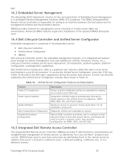
... require the installation of interdependent pieces: Dell Lifecycle Controller Unified Server Configurator iDRAC6 Dell Lifecycle Controller powers the embedded management features. Dell Unified Server Configurator (USC) is comprised of the optional iDRAC6 Enterprise card. 16.4 Dell Lifecycle...Configurator includes those shown in a pre-OS environment. PowerEdge R710 Technical Guide 55 Dell 16.3 Embedded Server Management The PowerEdge R710 implements circuitry for the next generation of the Dell logo's appearance during the system boot process. Current ...
... require the installation of interdependent pieces: Dell Lifecycle Controller Unified Server Configurator iDRAC6 Dell Lifecycle Controller powers the embedded management features. Dell Unified Server Configurator (USC) is comprised of the optional iDRAC6 Enterprise card. 16.4 Dell Lifecycle...Configurator includes those shown in a pre-OS environment. PowerEdge R710 Technical Guide 55 Dell 16.3 Embedded Server Management The PowerEdge R710 implements circuitry for the next generation of the Dell logo's appearance during the system boot process. Current ...

Technical Guide
Page 56
...Media card. Key features for the iDRAC6 Enterprise include: Scripting capability with Dell's racadm command line Remote video, keyboard, and mouse control with Virtual ...61623; iDRAC6 with vFlash Media is provided for large enterprise customers with requirements for system management automation. 16.6 iDRAC6 Express The iDRAC6 Express is mounted parallel...of remote access functions including authentication, authorization, and encryption Power control and management with stand-offs. PowerEdge R710 Technical Guide 56 In addition to providing a Lifecycle Controller, the ...
...Media card. Key features for the iDRAC6 Enterprise include: Scripting capability with Dell's racadm command line Remote video, keyboard, and mouse control with Virtual ...61623; iDRAC6 with vFlash Media is provided for large enterprise customers with requirements for system management automation. 16.6 iDRAC6 Express The iDRAC6 Express is mounted parallel...of remote access functions including authentication, authorization, and encryption Power control and management with stand-offs. PowerEdge R710 Technical Guide 56 In addition to providing a Lifecycle Controller, the ...


